EP1430355B1 - Eine erste und zweite unterschicht enthaltende orientierungsschicht - Google Patents
Eine erste und zweite unterschicht enthaltende orientierungsschicht Download PDFInfo
- Publication number
- EP1430355B1 EP1430355B1 EP02777198A EP02777198A EP1430355B1 EP 1430355 B1 EP1430355 B1 EP 1430355B1 EP 02777198 A EP02777198 A EP 02777198A EP 02777198 A EP02777198 A EP 02777198A EP 1430355 B1 EP1430355 B1 EP 1430355B1
- Authority
- EP
- European Patent Office
- Prior art keywords
- sublayer
- alignment
- regions
- liquid crystal
- aligning
- Prior art date
- Legal status (The legal status is an assumption and is not a legal conclusion. Google has not performed a legal analysis and makes no representation as to the accuracy of the status listed.)
- Expired - Lifetime
Links
- 239000000463 material Substances 0.000 claims abstract description 79
- 239000004973 liquid crystal related substance Substances 0.000 claims abstract description 70
- 230000003287 optical effect Effects 0.000 claims abstract description 7
- 238000004519 manufacturing process Methods 0.000 claims abstract description 5
- 239000010410 layer Substances 0.000 claims description 74
- 125000003636 chemical group Chemical group 0.000 claims description 46
- 239000013545 self-assembled monolayer Substances 0.000 claims description 22
- 239000002243 precursor Substances 0.000 claims description 17
- 238000000034 method Methods 0.000 claims description 14
- 230000005855 radiation Effects 0.000 claims description 12
- 229920000642 polymer Polymers 0.000 claims description 11
- 239000000126 substance Substances 0.000 claims description 9
- 238000000151 deposition Methods 0.000 claims description 6
- 230000001678 irradiating effect Effects 0.000 claims description 6
- 239000012044 organic layer Substances 0.000 claims description 6
- 239000002356 single layer Substances 0.000 claims description 5
- 238000006243 chemical reaction Methods 0.000 claims description 4
- 238000005192 partition Methods 0.000 claims description 4
- 238000009877 rendering Methods 0.000 claims description 4
- 239000007787 solid Substances 0.000 claims description 4
- 239000002094 self assembled monolayer Substances 0.000 claims description 3
- 239000013047 polymeric layer Substances 0.000 claims description 2
- 239000000758 substrate Substances 0.000 description 33
- 150000003573 thiols Chemical class 0.000 description 19
- 238000004873 anchoring Methods 0.000 description 17
- OXBLVCZKDOZZOJ-UHFFFAOYSA-N 2,3-Dihydrothiophene Chemical compound C1CC=CS1 OXBLVCZKDOZZOJ-UHFFFAOYSA-N 0.000 description 10
- 239000010408 film Substances 0.000 description 7
- PCHJSUWPFVWCPO-UHFFFAOYSA-N gold Chemical compound [Au] PCHJSUWPFVWCPO-UHFFFAOYSA-N 0.000 description 7
- 239000010931 gold Substances 0.000 description 7
- 229910052737 gold Inorganic materials 0.000 description 7
- 239000003999 initiator Substances 0.000 description 7
- 230000010287 polarization Effects 0.000 description 7
- LFQSCWFLJHTTHZ-UHFFFAOYSA-N Ethanol Chemical compound CCO LFQSCWFLJHTTHZ-UHFFFAOYSA-N 0.000 description 6
- 239000004642 Polyimide Substances 0.000 description 6
- 239000011521 glass Substances 0.000 description 6
- 229920001721 polyimide Polymers 0.000 description 6
- 239000000243 solution Substances 0.000 description 6
- 125000003396 thiol group Chemical group [H]S* 0.000 description 6
- KFZMGEQAYNKOFK-UHFFFAOYSA-N Isopropanol Chemical compound CC(C)O KFZMGEQAYNKOFK-UHFFFAOYSA-N 0.000 description 5
- 238000007259 addition reaction Methods 0.000 description 5
- IJGRMHOSHXDMSA-UHFFFAOYSA-N Atomic nitrogen Chemical compound N#N IJGRMHOSHXDMSA-UHFFFAOYSA-N 0.000 description 4
- 238000006352 cycloaddition reaction Methods 0.000 description 4
- 238000005259 measurement Methods 0.000 description 4
- 125000000391 vinyl group Chemical group [H]C([*])=C([H])[H] 0.000 description 4
- 238000010521 absorption reaction Methods 0.000 description 3
- WBYWAXJHAXSJNI-UHFFFAOYSA-N cinnamic acid Chemical class OC(=O)C=CC1=CC=CC=C1 WBYWAXJHAXSJNI-UHFFFAOYSA-N 0.000 description 3
- ZYGHJZDHTFUPRJ-UHFFFAOYSA-N coumarin Chemical compound C1=CC=C2OC(=O)C=CC2=C1 ZYGHJZDHTFUPRJ-UHFFFAOYSA-N 0.000 description 3
- WNAHIZMDSQCWRP-UHFFFAOYSA-N dodecane-1-thiol Chemical compound CCCCCCCCCCCCS WNAHIZMDSQCWRP-UHFFFAOYSA-N 0.000 description 3
- 230000031700 light absorption Effects 0.000 description 3
- 239000007788 liquid Substances 0.000 description 3
- 238000000813 microcontact printing Methods 0.000 description 3
- 239000000203 mixture Substances 0.000 description 3
- 238000006116 polymerization reaction Methods 0.000 description 3
- -1 thiol compound Chemical class 0.000 description 3
- WYURNTSHIVDZCO-UHFFFAOYSA-N Tetrahydrofuran Chemical compound C1CCOC1 WYURNTSHIVDZCO-UHFFFAOYSA-N 0.000 description 2
- 125000000217 alkyl group Chemical group 0.000 description 2
- 238000000576 coating method Methods 0.000 description 2
- 239000004020 conductor Substances 0.000 description 2
- 235000001671 coumarin Nutrition 0.000 description 2
- 150000004775 coumarins Chemical class 0.000 description 2
- 230000008878 coupling Effects 0.000 description 2
- 238000010168 coupling process Methods 0.000 description 2
- 238000005859 coupling reaction Methods 0.000 description 2
- VTXVGVNLYGSIAR-UHFFFAOYSA-N decane-1-thiol Chemical compound CCCCCCCCCCS VTXVGVNLYGSIAR-UHFFFAOYSA-N 0.000 description 2
- 238000011161 development Methods 0.000 description 2
- 239000004205 dimethyl polysiloxane Substances 0.000 description 2
- 238000001035 drying Methods 0.000 description 2
- 230000005684 electric field Effects 0.000 description 2
- 238000010438 heat treatment Methods 0.000 description 2
- ORTRWBYBJVGVQC-UHFFFAOYSA-N hexadecane-1-thiol Chemical compound CCCCCCCCCCCCCCCCS ORTRWBYBJVGVQC-UHFFFAOYSA-N 0.000 description 2
- 230000006872 improvement Effects 0.000 description 2
- AMGQUBHHOARCQH-UHFFFAOYSA-N indium;oxotin Chemical compound [In].[Sn]=O AMGQUBHHOARCQH-UHFFFAOYSA-N 0.000 description 2
- 230000001939 inductive effect Effects 0.000 description 2
- 230000000977 initiatory effect Effects 0.000 description 2
- 238000010406 interfacial reaction Methods 0.000 description 2
- 229910052757 nitrogen Inorganic materials 0.000 description 2
- 238000000879 optical micrograph Methods 0.000 description 2
- 238000000059 patterning Methods 0.000 description 2
- 229920000435 poly(dimethylsiloxane) Polymers 0.000 description 2
- 238000012545 processing Methods 0.000 description 2
- 150000003254 radicals Chemical class 0.000 description 2
- 239000002904 solvent Substances 0.000 description 2
- XLYOFNOQVPJJNP-UHFFFAOYSA-N water Substances O XLYOFNOQVPJJNP-UHFFFAOYSA-N 0.000 description 2
- 239000012956 1-hydroxycyclohexylphenyl-ketone Substances 0.000 description 1
- OZAIFHULBGXAKX-UHFFFAOYSA-N 2-(2-cyanopropan-2-yldiazenyl)-2-methylpropanenitrile Chemical compound N#CC(C)(C)N=NC(C)(C)C#N OZAIFHULBGXAKX-UHFFFAOYSA-N 0.000 description 1
- OZAIFHULBGXAKX-VAWYXSNFSA-N AIBN Substances N#CC(C)(C)\N=N\C(C)(C)C#N OZAIFHULBGXAKX-VAWYXSNFSA-N 0.000 description 1
- NIXOWILDQLNWCW-UHFFFAOYSA-M Acrylate Chemical compound [O-]C(=O)C=C NIXOWILDQLNWCW-UHFFFAOYSA-M 0.000 description 1
- XWUNIDGEMNBBAQ-UHFFFAOYSA-N Bisphenol A ethoxylate diacrylate Chemical compound C=1C=C(OCCOC(=O)C=C)C=CC=1C(C)(C)C1=CC=C(OCCOC(=O)C=C)C=C1 XWUNIDGEMNBBAQ-UHFFFAOYSA-N 0.000 description 1
- 238000007698 E/Z-isomerization reaction Methods 0.000 description 1
- 239000004988 Nematic liquid crystal Substances 0.000 description 1
- 239000000853 adhesive Substances 0.000 description 1
- 230000001070 adhesive effect Effects 0.000 description 1
- 125000001931 aliphatic group Chemical group 0.000 description 1
- 150000001356 alkyl thiols Chemical class 0.000 description 1
- 125000003277 amino group Chemical group 0.000 description 1
- 238000004458 analytical method Methods 0.000 description 1
- 238000013459 approach Methods 0.000 description 1
- 230000000712 assembly Effects 0.000 description 1
- 238000000429 assembly Methods 0.000 description 1
- MQDJYUACMFCOFT-UHFFFAOYSA-N bis[2-(1-hydroxycyclohexyl)phenyl]methanone Chemical compound C=1C=CC=C(C(=O)C=2C(=CC=CC=2)C2(O)CCCCC2)C=1C1(O)CCCCC1 MQDJYUACMFCOFT-UHFFFAOYSA-N 0.000 description 1
- 239000003795 chemical substances by application Substances 0.000 description 1
- 238000004140 cleaning Methods 0.000 description 1
- 238000010668 complexation reaction Methods 0.000 description 1
- 150000001875 compounds Chemical class 0.000 description 1
- 238000010276 construction Methods 0.000 description 1
- 229960000956 coumarin Drugs 0.000 description 1
- 239000002178 crystalline material Substances 0.000 description 1
- 230000007547 defect Effects 0.000 description 1
- 230000008021 deposition Effects 0.000 description 1
- 239000003599 detergent Substances 0.000 description 1
- 238000004090 dissolution Methods 0.000 description 1
- 239000002019 doping agent Substances 0.000 description 1
- 239000000428 dust Substances 0.000 description 1
- 238000003384 imaging method Methods 0.000 description 1
- 238000007654 immersion Methods 0.000 description 1
- 239000003112 inhibitor Substances 0.000 description 1
- 238000007641 inkjet printing Methods 0.000 description 1
- 230000001788 irregular Effects 0.000 description 1
- 230000000873 masking effect Effects 0.000 description 1
- 238000012544 monitoring process Methods 0.000 description 1
- 239000000178 monomer Substances 0.000 description 1
- 229920003986 novolac Polymers 0.000 description 1
- 125000002524 organometallic group Chemical group 0.000 description 1
- 238000001907 polarising light microscopy Methods 0.000 description 1
- 230000002028 premature Effects 0.000 description 1
- 238000007639 printing Methods 0.000 description 1
- 230000008569 process Effects 0.000 description 1
- 230000002035 prolonged effect Effects 0.000 description 1
- 238000010526 radical polymerization reaction Methods 0.000 description 1
- 230000009467 reduction Effects 0.000 description 1
- 238000011160 research Methods 0.000 description 1
- 229920005989 resin Polymers 0.000 description 1
- 239000011347 resin Substances 0.000 description 1
- 239000000344 soap Substances 0.000 description 1
- 239000008149 soap solution Substances 0.000 description 1
- 210000004872 soft tissue Anatomy 0.000 description 1
- 125000006850 spacer group Chemical group 0.000 description 1
- 238000009987 spinning Methods 0.000 description 1
- 238000004544 sputter deposition Methods 0.000 description 1
- 239000003381 stabilizer Substances 0.000 description 1
- 230000003068 static effect Effects 0.000 description 1
- 239000004094 surface-active agent Substances 0.000 description 1
- YLQBMQCUIZJEEH-UHFFFAOYSA-N tetrahydrofuran Natural products C=1C=COC=1 YLQBMQCUIZJEEH-UHFFFAOYSA-N 0.000 description 1
- 239000010409 thin film Substances 0.000 description 1
- 238000012546 transfer Methods 0.000 description 1
- 230000007704 transition Effects 0.000 description 1
- 238000000411 transmission spectrum Methods 0.000 description 1
- 238000002834 transmittance Methods 0.000 description 1
- 238000009281 ultraviolet germicidal irradiation Methods 0.000 description 1
- 238000000870 ultraviolet spectroscopy Methods 0.000 description 1
- 238000001392 ultraviolet--visible--near infrared spectroscopy Methods 0.000 description 1
- 238000007740 vapor deposition Methods 0.000 description 1
- 229920002554 vinyl polymer Polymers 0.000 description 1
- 238000009736 wetting Methods 0.000 description 1
Images
Classifications
-
- G—PHYSICS
- G02—OPTICS
- G02F—OPTICAL DEVICES OR ARRANGEMENTS FOR THE CONTROL OF LIGHT BY MODIFICATION OF THE OPTICAL PROPERTIES OF THE MEDIA OF THE ELEMENTS INVOLVED THEREIN; NON-LINEAR OPTICS; FREQUENCY-CHANGING OF LIGHT; OPTICAL LOGIC ELEMENTS; OPTICAL ANALOGUE/DIGITAL CONVERTERS
- G02F1/00—Devices or arrangements for the control of the intensity, colour, phase, polarisation or direction of light arriving from an independent light source, e.g. switching, gating or modulating; Non-linear optics
- G02F1/01—Devices or arrangements for the control of the intensity, colour, phase, polarisation or direction of light arriving from an independent light source, e.g. switching, gating or modulating; Non-linear optics for the control of the intensity, phase, polarisation or colour
- G02F1/13—Devices or arrangements for the control of the intensity, colour, phase, polarisation or direction of light arriving from an independent light source, e.g. switching, gating or modulating; Non-linear optics for the control of the intensity, phase, polarisation or colour based on liquid crystals, e.g. single liquid crystal display cells
- G02F1/133—Constructional arrangements; Operation of liquid crystal cells; Circuit arrangements
- G02F1/1333—Constructional arrangements; Manufacturing methods
- G02F1/1337—Surface-induced orientation of the liquid crystal molecules, e.g. by alignment layers
- G02F1/13378—Surface-induced orientation of the liquid crystal molecules, e.g. by alignment layers by treatment of the surface, e.g. embossing, rubbing or light irradiation
-
- G—PHYSICS
- G02—OPTICS
- G02F—OPTICAL DEVICES OR ARRANGEMENTS FOR THE CONTROL OF LIGHT BY MODIFICATION OF THE OPTICAL PROPERTIES OF THE MEDIA OF THE ELEMENTS INVOLVED THEREIN; NON-LINEAR OPTICS; FREQUENCY-CHANGING OF LIGHT; OPTICAL LOGIC ELEMENTS; OPTICAL ANALOGUE/DIGITAL CONVERTERS
- G02F1/00—Devices or arrangements for the control of the intensity, colour, phase, polarisation or direction of light arriving from an independent light source, e.g. switching, gating or modulating; Non-linear optics
- G02F1/01—Devices or arrangements for the control of the intensity, colour, phase, polarisation or direction of light arriving from an independent light source, e.g. switching, gating or modulating; Non-linear optics for the control of the intensity, phase, polarisation or colour
- G02F1/13—Devices or arrangements for the control of the intensity, colour, phase, polarisation or direction of light arriving from an independent light source, e.g. switching, gating or modulating; Non-linear optics for the control of the intensity, phase, polarisation or colour based on liquid crystals, e.g. single liquid crystal display cells
- G02F1/133—Constructional arrangements; Operation of liquid crystal cells; Circuit arrangements
- G02F1/1333—Constructional arrangements; Manufacturing methods
- G02F1/1337—Surface-induced orientation of the liquid crystal molecules, e.g. by alignment layers
- G02F1/133753—Surface-induced orientation of the liquid crystal molecules, e.g. by alignment layers with different alignment orientations or pretilt angles on a same surface, e.g. for grey scale or improved viewing angle
-
- C—CHEMISTRY; METALLURGY
- C09—DYES; PAINTS; POLISHES; NATURAL RESINS; ADHESIVES; COMPOSITIONS NOT OTHERWISE PROVIDED FOR; APPLICATIONS OF MATERIALS NOT OTHERWISE PROVIDED FOR
- C09K—MATERIALS FOR MISCELLANEOUS APPLICATIONS, NOT PROVIDED FOR ELSEWHERE
- C09K2323/00—Functional layers of liquid crystal optical display excluding electroactive liquid crystal layer characterised by chemical composition
- C09K2323/02—Alignment layer characterised by chemical composition
Definitions
- the invention pertains to an alignment layer capable of aligning liquid crystal material.
- the invention further pertains to an optical or electro-optical device comprising the alignment layer, and to a method of manufacturing said layer.
- Alignment layers for aligning a liquid crystal material are conventionally made of rubbed polyimide.
- the rubbing process creates dust and causes static charging of the substrate to which the layer is applied, making it incompatible with clean room environments and introducing defects in the alignment layers.
- Alternative alignment layers are isotropic polymer layers carrying embossed micro-grooves, and photo-alignment layers of photo-polymers, which may be rendered capable of aligning liquid crystal material by means of irradiation with polarized light.
- alignment layers comprising self-assembled monolayers (SAM's) provided onto a gold substrate suffer from limited transparency due to light absorption by the gold substrate. It was shown by Gupta and Abbott, Science, 276, pp. 1533-1536, 1997 , that it is possible to use SAM's of alkanethiols on gold to induce the controlled alignment of liquid crystals deposited on monolayers. Through micro-contact printing techniques it was possible to induce both homeotropic and planar alignment within one substrate. Depending on the type of alkanethiol and the method of gold deposition both the azimuthal (in the plane of the substrate) and the polar (away from the substrate) angle of the anchoring liquid crystal can be controlled.
- SAM's self-assembled monolayers
- this light absorption influences the performance of flat panel displays independent of whether they are used in the transmissive, transreflective, or reflective mode. In all cases the light absorption causes light losses and a reduction in energy efficiency of battery life of the liquid crystal display. More importantly, the production of full color displays with high color purity becomes at least very problematic.
- JP 10-153783 an alignment film was disclosed without the need of a rubbing treatment.
- the alignment film was provided onto a novolak resin, which was exposed to UV irradiation through a mask to form a monomolecular layer by chemical reaction with a tetra-alkyl silane compound.
- a tetra-alkyl silane compound a tetra-alkyl silane compound.
- an alignment film can be formed with regions capable of orienting liquid crystalline material. This device, however, allows orientation in one direction only.
- US 4,277,144 describes in column 4 a first (inorganic) layer (15) which can act as an alignment layer, and which is covered by a second (inorganic) alignment layer (16). Layers 15 and 16 are not chemically linked to each other.
- EP 613,037 describes in Fig. 15 a device comprising an alignment layer.
- This layer is a single layer that does not comprise two sublayers that are chemically bonded to each other.
- the invention more particularly, pertains to the molecular alignment of liquid crystals at interfaces of layers.
- the alignment is of practical relevance for displays based on liquid crystals, for security marks and for electro-optical devices that are used as light switches, for instance in telecommunication systems.
- Liquid crystals are well known for their ability to switch light when they are brought from one alignment type to another for instance by an electrical field. Thereto the field-off alignment is established by bringing the liquid crystals in contact with substrates that are provided with special coatings.
- Coatings which are known to give liquid crystal alignment and which are nowadays widely used are thin, e.g. 200 nm, polyimide layers that are rubbed by soft tissue.
- This rubbing or buffing provides a preferential orientation in the surface of the polyimide, which may molecular (aligned polymeric chains) or macroscopic (nanometer scale scratches) in nature.
- the alignment is taken over when a liquid crystal is brought on top of the rubbed polyimide.
- the alignment is planar or planar with a small tilt angle, depending on the composition of the polyimide.
- Another alignment principle is based on treatment of the surface with surfactant type of molecules. Known are for instance gold surfaces that are treated with thiol molecules, which provides planar or vertical (homeotropic) alignment, depending on the type of thiol and treatment method. By these alignment methods it is difficult to achieve multiple alignment directions on one single substrate.
- the invention now provides a means to give an orientating polymer layer that may combine planar alignment of the liquid crystals in various directions together with vertical or azimuthal alignment. More generally, the invention provides in an alignment layer wherein the first and/or the second sublayer is capable of aligning the liquid crystal material in a planar, an azimuthal or a homeotropic alignment.
- the invention therefore relates to an alignment layer capable of aligning liquid crystal material, the alignment layer comprising:
- the invention relates to a method of manufacturing an alignment layer capable of aligning a liquid crystal material, comprising:
- the principle can, for instance, be as follows.
- a first sublayer of a polyvinylcinnamate type of material is spun on a glass substrate. This layer can be exposed through a mask to give local planar alignment.
- the whole surface, containing exposed and unexposed areas, is now brought in contact with a thiol-containing solution.
- a thermal initiator and by the use of some heating the thiol groups are reacted with the surface double bonds that remained after the first exposure.
- the excess of thiols are washed away.
- the surface aligns the liquid crystal vertically. In this way a planar alignment is combined with a vertical alignment in a very controlled way.
- this method can be used, for instance, instead of a polyvinylcinnamate other olefinic polymers can be used.
- these materials can undergo [2+2] photo-cycloaddition reaction that yields structures that align liquid crystals in a controlled way.
- coumarin-containing polymers as described by Schadt et al. in Nature ( Schadt, M., Seiberle, H., Schuster, A., Nature, 381, 212-215 (1996) ).
- the first and the second sublayer are chemically linked at an interface of the first and the second sublayer.
- the term "chemically linked” means that a covalent, an organo-metalic, or an ionic bond is formed, or that the sublayers are bonded by complexation.
- the chemical linking is performed by means of a reaction between a first chemical group present on the first sublayer at the interface and a second chemical group present on the second sublayer at the interface
- the method comprises:
- the first chemical group comprises an unsaturated moiety
- the second chemical group is a thiol group, an amino group or a group, which is photo-cleavable or thermo-cleavable to produce a free radical.
- Preferred alignment layers have a first sublayer, which is a solid organic layer, preferably a polymeric layer or a polymer precursor layer and preferably the second sublayer is a solid organic layer, a photo-patternable organic layer, an organic monolayer, or an organic self-assembled monolayer.
- a polymer precursor layer is a layer of a precursor that can be polymerized by applying irradiation or heat. Such layers include layers of photo-polymers.
- the invention is one of the first and second chemical groups sensitive to actinic radiation such that when having received a suitable dose of such radiation, said chemical group is at least to a lesser extent capable of reacting with the other chemical group, than when said chemical group was not irradiated.
- one of the first and second chemical groups is obtainable by means of actinic radiation from a precursor group or a combination of precursor groups, which is at least to a lesser extent capable of reacting with the other chemical group than the group obtained from the precursor group or the combination of precursor groups.
- the photoinduced E/Z isomerization also plays a role in the LC alignment by cinnamates.
- planar alignment of liquid crystals is achieved using linearly polarized UV, and alignment directions both parallel and perpendicular to the polarization direction of the light can be established.
- high pre-tilts of anchoring liquid crystals leading to homeotropic alignment have been difficult to accomplish, certainly by using only one photo-alignment material within a substrate. To illustrate the patterning options, a photo-alignment material was irradiated with polarized UV light.
- the class of the photo-alignment material was described in the literature.
- the material demonstrates alignment of the liquid crystal parallel to the direction of the electrical field of the polarized light to which it was exposed, as was shown for the coumarin derivatives.
- the material will be referred to as linear photo-polymerized (LPP) material.
- irradiation conditions are an important parameter for the outcome of the liquid crystal anchoring. Irradiation of the LPP precursor by uncollimated, unpolarized UV light resulted in random alignment of liquid crystals, as expected. The alignment resulting from irradiation by (uncollimated) linearly polarized UV light strongly depended on the exposure time. Short exposure times (e.g. 35 minutes) resulted in a homeotropic anchoring. However, the homeotropic anchoring does not represent a stable, fully cured state, as the LC alignment changed from homeotropic to planar upon continued UV exposure (e.g. additionally 25 minutes). Similar observations have been reported before where the direction of planar alignment with respect to the polarization direction of the UV light was changed upon longer exposure.
- a novel concept is introduced that may result in stable patterned homeotropic and bi-directional planar aligned areas within one substrate.
- a thiolene addition reaction can be utilized to covalently link a SAM to the photo-alignment layer.
- SAM as used in the present invention means a self assembled monolayer, or a similar layer comprising areas of irregular order and/or which may contain regions with more than one layer of molecules.
- planar anchoring is introduced by conventional masking techniques resulting to photo-alignment through linear polarized UV light. Subsequently, the substrate is covered with a thiol compound and the thiolene addition reaction is initiated. After removing the excess thiol and subsequent cell construction, planar anchoring should be observed at the photo-aligned areas, whereas homeotropic anchoring should be observed at those areas where the SAM is covalently linked to the photo-alignment material, i.e. at the uncovered area thiolene addition covalently links a SAM to the unreacted vinyl groups inducing a homeotropic anchoring.
- LPP material was spun onto a substrate and partly aligned in a planar fashion using linear polarized UV light.
- the addition can be initiated by direct UV-initiated coupling, with or without the aid of a photo-initiator, or by other sources of free radicals, such as thermal initiators.
- After immersion of the partly planar aligned substrate in n-dodecanethiol direct coupling of the thiol to the not yet reacted double bonds of the LPP material was attempted by direct UV-exposure with and without a photo-initiator added to the liquid thiol. This did not result in a homeotropic alignment of the designated area.
- the cycloaddition reaction of the LPP material predominates the thiolene addition.
- attempts to selectively excite the thiolene addition reaction by UV exposure of a single wavelength (365 nm) gave the same negative result.
- the initiation of the thiolene addition reaction was brought about through thermal initiation.
- the substrate can be shielded from premature UV exposure and the cycloaddition of the LPP material may be decoupled from the thiolene addition.
- the thermal stability of the LPP precursor certainly favors the decoupling approach, as was confirmed by monitoring by UV-VIS spectroscopy of the absorption band of the LPP precursor at elevated temperatures (e.g. at 100°C) for at least one hour.
- elevated temperatures e.g. at 100°C
- a cell was constructed.
- the thus treated LPP layer constitutes only of one substrate whereas the opposite substrate comprises a conventional rubbed planar polyimide layer with an orientation direction perpendicular to the photo-aligned substrate.
- the results according to the invention demonstrate the versatility of photo-alignment materials.
- Planar anchoring of liquid crystals can be accomplished in every direction by adjusting the polarization direction of the UV light.
- a novel concept enabling the stable homeotropic anchoring by using covalently linked SAM's within a single substrate, opens a new field for the complete control of anchoring of liquid crystals. This is especially important for the further improvement of the optical characteristics of liquid crystal devices and could be the starting point for the development of completely novel display concepts.
- the induced alignment of liquid crystals i.e. homeotropic or planar orientation
- the choice with respect to the type of molecule used to construct the SAM's is not limited to the molecules described above, but can be selected from many suitable compounds, as is evident to the person skilled in the field.
- the liquid crystal layers comprise regions, which are functionalized by homeotropic alignment, and regions with non-functionalized (e.g. planar) alignment.
- the functionalized homeotropic regions can be exploited to start polymerization in a homeotropic direction.
- ITO indium tinoxide
- ITO is the preferred transparent electrical conductor.
- the presence of a vinyl tail-group originating from the thiol used, opens up an interesting range of possibilities.
- the reactive group can be used to further modify the surface of the SAM, for instance to adjust the surface free energy and hence its wetting properties by replacing the apolar vinyl group by a more polar tail-group.
- the vinyl group can be exploited as starting point for thiolene polymerization or as starting point of conventional free-radical polymerization, thus extending the possibilities for further morphology control and adhesion promotion.
- Bi-directional control of the planar alignment was achieved by using photo-alignment layers. Moreover, a novel concept of covalently linking SAM's to double bonds of the photo-alignment material enables stable homeotropic anchoring within the same substrate.
- the control over the morphology within liquid crystal devices can be even further improved. This is especially important for the improvement of the (electro-)optical properties of liquid crystal devices and provides new opportunities for the development of display concepts.
- UV exposure with incoming light along the normal also oblique exposure may be used to lead to pretilted alignment in the photo-aligned areas.
- alkylthiols instead of the described alkylthiols also other thiol groups can be used, e.g. functionalized by special end-groups to the alkyl tail.
- thiol groups instead of thiol groups also other reactive groups can be considered that react to a double bond. It even may be double bonds themselves comparable to the ones that exist in the first sublayer. In that case the cinnamates or cinnamates-like groups must be provided with, for instance, long tail aliphatic groups in order to provide homeotropic alignment.
- the first sublayer of the alignment layer may be obtainable from a photo-alignable material, which upon irradiation with linearly polarized light, may be rendered capable of aligning the liquid crystal material with a first alignment.
- the exposed (non-covered) regions of the first sublayer comprise material capable of aligning the liquid crystal material in a first alignment, said material being obtainable by providing a layer of photo-alignable material which is rendered capable of aligning the liquid crystal material in a first alignment when subjected to linearly polarized light and then subjecting at least at the positions corresponding to the exposed regions to linearly polarized light.
- the first sublayer is obtainable from a photo-alignable material having an actinic-radiation sensitive chemical group which, when present at the interface between the first and the second sublayer, is capable of reacting with the second chemical group to form a chemical link between the first and the second sublayer.
- the second sublayer may be a monolayer, such as an R-SH monolayer, R being an organic, such as an alkyl, or an organo-metallic group.
- the second chemical group is a thiol group.
- the interfacial reaction is thermally-induced, radiation-induced, or photo-induced, optionally, in the presence of initiators, sensitizers, inhibitors, stabilizers and/or transfer agents.
- the interfacial reaction is preferably carried out by the reaction at selected locations in accordance with the desired pattern by, for example, pattern-wise heating or pattern-wise irradiation, and then removing any material covering the first sublayer at the non-selected locations.
- the second sublayer may also be obtainable by pattern-wise depositing a second sublayer-forming material onto the fist sublayer.
- the first sublayer may also have a rubbed surface capable of aligning the liquid crystal material or comprises, optionally in accordance with a desired pattern, photo-aligned material capable of aligning the liquid crystal material.
- the first sublayer may also comprise a photo-aligned material capable of aligning the liquid crystal material, optionally in accordance with a desired pattern, obtainable by exposing a layer of photo-alignable material in accordance with the desired pattern before, simultaneous to and/or after the chemical linking of the first sublayer to the second sublayer.
- Patterning may be carried out by means of, for example, a wet deposition method such as printing, micro-contact printing, ink-jet printing or a gas-phase deposition method such as vapor deposition or sputtering.
- a wet deposition method such as printing, micro-contact printing, ink-jet printing or a gas-phase deposition method such as vapor deposition or sputtering.
- the cleaning detergent, Extran MA 01 alkalic soap, the nematic liquid crystal mixture E7 and the chiral dopant ZLI 811 were supplied by Merck, Amsterdam, The Netherlands.
- the thiols 1-decanethiol (96%), 1-dodecanethiol (98%), 1- hexadecanethiol (95%; Fluka Chemika) were purchased from Sigma-Aldrich Chem. Co., Zwijndrecht, The Netherlands.
- the solvents ethanol (99.9%) and 2-propanol (99.8%) were obtained from Biosolve B.V., Valkenswaard, The Netherlands. All chemicals were used as delivered.
- a photo-alignment precursor LPP JP-265 was obtained from Rolic Ltd., Basel, Switzerland.
- UV-VIS transmission spectra were determined using a Shimadzu UV-3102 PC UV-VIS-NIR scanning spectrophotometer. All measurements were conducted at room temperature against air. The wavelength range was set at 300-700 nm with a slit width of 2 mm at a fast measurement speed. The error in the obtained transmittance values was determined to be within 4%.
- Polarized optical microscopy was performed with an Axioplan 2 imaging microscope equipped with a digital camera.
- Self-assembled monolayers were prepared from 1 mM solutions of a thiol in ethanol or tetrahydrofuran. Substrates with a deposited gold film were immersed in approximately 15 ml of the solution for three minutes. Subsequently, the substrates were rinsed with the corresponding solvent and dried under nitrogen.
- Micro-contact prints were prepared from polydimethylsiloxane (PDMS) stamps, and inked with the appropriate thiol.
- PDMS polydimethylsiloxane
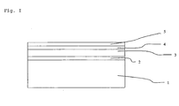
- the substrates used consist of several layers deposited on a glass substrate.
- a typical configuration is indicated in Figure I .
- a transparent electrical conductor 2 preferably indium tinoxide (ITO) is applied.
- ITO indium tinoxide
- the second sublayer 4 is deposited, for instance by depositing a SAM by micro-contact printing.
- a liquid crystal layer 5 is applied.
- other layers such as a cover layer (not shown), may also be applied.
- Curing of the photo-alignment material was done by placing the substrate under an uncollimated UV light source (Philips type HB 172, 75 W, 4x Philips 15 W UV-type 3) and irradiating the surface through a UV-polarizer.
- an uncollimated UV light source Philips type HB 172, 75 W, 4x Philips 15 W UV-type 3
- Covalent attachment of a SAM 4 to the not yet reacted photo-alignment material was done by dissolution of 1% w/w of a thermal initiator (2,2-azobis(isobutyronitrile); AIBN; half-life 12 min at 101°C) in a thiol by placing the solution in an ultrasonic both for at least 10 minutes.
- a thermal initiator (2,2-azobis(isobutyronitrile); AIBN; half-life 12 min at 101°C) in a thiol by placing the solution in an ultrasonic both for at least 10 minutes.
- the thiols used were n-dodecanethiol or a 20/80 w/w mixture of 1-hexadecanethiol and 1-decanethiol.
- the thiol solution was added to the substrate, placed on a thermostated hot-stage (95-120°C), using a syringe equipped with a 0.2 ⁇ m filter to cover the entire surface. Occasionally, thiol solution was added when dewetting of the surface was noted. After 2 hours, the substrate was removed and the excess thiol and initiator gently removed by rinsing with ethanol and subsequent drying under nitrogen.
- Cells were constructed by pairing two substrates and fixing them using a UV-curable acrylate based adhesive (bisphenol A ethoxylate diacrylate containing 0.5% w/w 1-hydroxy cyclohexyl phenylketone).
- the cell gap was set using glass spacers (typically 4-15 ⁇ m; Philips Research, Eindhoven, The Netherlands).
- the cells were filled (“layer 5") using capillary motion with a liquid crystal at elevated temperature, well above the clearing point of the mesogen. After complete filling, the cell was allowed to gradually cool down to room temperature.
Landscapes
- Physics & Mathematics (AREA)
- Nonlinear Science (AREA)
- Spectroscopy & Molecular Physics (AREA)
- Mathematical Physics (AREA)
- Chemical & Material Sciences (AREA)
- Crystallography & Structural Chemistry (AREA)
- General Physics & Mathematics (AREA)
- Optics & Photonics (AREA)
- Liquid Crystal (AREA)
- Polarising Elements (AREA)
- Heat Sensitive Colour Forming Recording (AREA)
- Medicinal Preparation (AREA)
Claims (11)
- Orientierungsschicht, die zum Orientieren von Flüssigkristall-Material eingerichtet ist, wobei die Orientierungsschicht aufweist:eine erste Unterschicht (3) mit Bereichen, die derart eingerichtet sind, dass sie das Flüssigkristall-Material in einer ersten Orientierung orientieren;eine zweite Unterschicht (4) mit Bereichen, die derart eingerichtet sind, dass sie das Flüssigkristall-Material in einer zweiten Orientierung orientieren,wobei die erste Orientierung und die zweite Orientierung zueinander verschieden sind;
wobei die zweite Unterschicht die erste Unterschicht überlappt und in Übereinstimmung mit einem vorgegebenen Muster die erste Unterschicht bedeckt, um an gewünschten Positionen zweite Unterschicht-Bereiche bereitzustellen, die derart eingerichtet sind, dass sie das Flüssigkristall-Material orientieren, und um an gewünschten Positionen Bereiche der darunter liegenden ersten Unterschicht bereitzustellen, die nicht von der zweiten Unterschicht bedeckt sind, dadurch gekennzeichnet, dass die erste Unterschicht an einer Grenzfläche zwischen der ersten Unterschicht und der zweiten Unterschicht an die zweite Unterschicht chemisch gebunden ist. - Orientierungsschicht gemäß Anspruch 1, wobei die erste Unterschicht (3) an die zweite Unterschicht (4) mittels einer Reaktion zwischen einer auf der ersten Unterschicht an der Grenzfläche vorhandenen ersten chemischen Gruppe und einer auf der zweiten Unterschicht an der Grenzfläche vorhandenen zweiten chemischen Gruppe chemisch gebunden ist.
- Orientierungsschicht gemäß Anspruch 1 oder 2, wobei die erste Unterschicht (3) eine organische Festkörper-Schicht, vorzugsweise eine Polymer-Schicht oder eine Polymer-Vorläufer-Schicht, ist und wobei die zweite Unterschicht (4) eine organische Festkörper-Schicht, vorzugsweise eine foto-strukturierbare organische Schicht, eine organische Monoschicht oder eine sich selbst zusammensetzende organische Monoschicht, ist.
- Orientierungsschicht gemäß einem der Ansprüche 1 bis 3, wobei eine der ersten und zweiten chemischen Gruppen sensitiv auf aktinische Strahlung ist, so dass diese chemische Gruppe, wenn sie eine geeignete Dosis an derartiger Strahlung empfangen hat, mindestens zu einem geringeren Ausmaß zum Reagieren mit der anderen chemischen Gruppe eingerichtet ist, als wenn diese chemische Gruppe nicht bestrahlt worden wäre.
- Orientierungsschicht gemäß einem der Ansprüche 1 bis 3, wobei die erste chemische Gruppe und die zweite chemische Gruppe mittels aktinischer Strahlung von einer Vorläufer-Gruppe oder einer Kombination aus Vorläufer-Gruppen, die mindestens in einem geringeren Ausmaß zum Reagieren mit der anderen chemischen Gruppe eingerichtet ist als die von der Vorläufer-Gruppe oder der Kombination aus Vorläufer-Gruppen erhaltene Gruppe, erhältlich sind.
- Orientierungsschicht gemäß einem der Ansprüche 1 bis 5, wobei die zweite Unterschicht (4) erhältlich ist, indem ein Material, das die zweite Unterschicht bildet, auf der ersten Unterschicht (3) muster-artig aufgebracht wird.
- Optische oder elektro-optische Vorrichtung, welche die Orientierungsschicht gemäß einem der Ansprüche 1 bis 6 aufweist.
- Optische oder elektro-optische Vorrichtung gemäß Anspruch 7, wobei die Vorrichtung ein Sicherheits-Merkmal auf einer Banknote, einer Kreditkarte oder anderen Objekten, die vor Fälschung geschützt werden sollen, ist.
- Verfahren zum Herstellen einer Orientierungsschicht, die zum Orientieren eines Flüssigkristall-Materials eingerichtet ist, aufweisend:- Bereitstellen einer ersten Unterschicht (3);- Bereitstellen einer gemusterten zweiten Unterschicht (4) auf der ersten Unterschicht, um die erste Unterschicht in bedeckte Bereiche und unbedeckte Bereiche aufzuteilen;- Einrichten der unbedeckten Bereiche der ersten Unterschicht derart, dass sie das Flüssigkristall-Material in eine erste Orientierung orientieren; und- Einrichten der Bereiche der zweiten Unterschicht, die die erste Unterschicht bedecken, derart, dass sie das Flüssigkristall-Material in eine zweite Orientierung orientieren, die von der ersten Orientierung verschieden ist, gekennzeichnet durch den Schritt des chemischen Bindens der ersten Unterschicht und der zweiten Unterschicht an einer Grenzfläche der ersten Unterschicht und der zweiten Unterschicht.
- Verfahren gemäß Anspruch 9, aufweisend:- Bereitstellen einer ersten Unterschicht (3) aus fotoorientierbarem Material, das erste chemische Gruppen aufweist;- auf der ersten Unterschicht und in Übereinstimmung mit einem vorgegebenen Muster, Bereitstellen einer zweiten Unterschicht (4) mit Bereichen, die derart eingerichtet sind, dass sie das Flüssigkristall-Material in eine zweite Orientierung orientieren, und die zweite chemische Gruppen aufweist, wobei das Muster derart ist, dass die erste Unterschicht in mittels der zweiten Unterschicht bedeckte Bereiche und in mittels der zweiten Unterschicht unbedeckte Bereiche aufgeteilt wird;- Ausbilden von chemischen Bindungen an der zwischen der ersten Unterschicht und der zweiten Unterschicht gebildeten Grenzfläche mittels Reagierens der ersten und zweiten chemischen Gruppen;- Aussetzen von mindestens den unbedeckten Bereichen der ersten Unterschicht einer linear polarisierten Strahlung, um belichtete Bereiche bereitzustellen, die derart eingerichtet sind, dass sie das Flüssigkristall-Material in eine erste Orientierung orientieren.
- Verfahren gemäß Anspruch 9, aufweisend:- Bereitstellen einer ersten Unterschicht (3) aus orientierbarem Material, das erste chemische Gruppen aufweist, die derart sensitiv auf aktinische Strahlung sind, dass auf Grund einer Bestrahlung des Materials die erste chemische Gruppe konvertiert wird, damit die erste chemische Gruppe mindestens zu einem geringeren Ausmaß zum Reagieren mit der zweiten chemischen Gruppe eingerichtet wird;- Bestrahlen der ersten Unterschicht in Übereinstimmung mit einem vorgegebenen Muster, um Bereiche, die erste chemische Gruppen, vorzugsweise einen ungesättigten Anteil, aufweisen, und belichtete Bereiche bereitzustellen, wobei die ersten chemischen Gruppen mindestens in einem geringeren Ausmaß zum Reagieren mit den zweiten chemischen Gruppen eingerichtet werden;- Aussetzen der ersten Unterschicht einem Orientierungs-Befähigungs-Mittel, um die erste Unterschicht zum Orientieren des Flüssigkristall-Materials in eine erste Orientierung einzurichten;- auf der ersten Unterschicht und optional in Übereinstimmung mit einem vorgegebenen Muster, Bereitstellen einer zweiten Unterschicht (4) mit Bereichen, die zum Orientieren des Flüssigkristall-Materials in eine zweite Orientierung eingerichtet sind, und die zweite chemische Gruppen aufweist;- Ausbilden von chemischen Bindungen an der zwischen der ersten Unterschicht und der zweiten Unterschicht gebildeten Grenzfläche mittels Reagierens der ersten und zweiten chemischen Gruppen;- Entfernen von Material der zweiten Unterschicht an belichteten Bereichen, um Bereiche der ersten Unterschicht freizulegen, die zum Orientieren des Flüssigkristall-Materials in eine erste Orientierung eingerichtet sind.
Priority Applications (1)
| Application Number | Priority Date | Filing Date | Title |
|---|---|---|---|
| EP02777198A EP1430355B1 (de) | 2001-09-24 | 2002-09-23 | Eine erste und zweite unterschicht enthaltende orientierungsschicht |
Applications Claiming Priority (6)
| Application Number | Priority Date | Filing Date | Title |
|---|---|---|---|
| EP01203611 | 2001-09-24 | ||
| EP01203611 | 2001-09-24 | ||
| EP01203744 | 2001-10-03 | ||
| EP01203744 | 2001-10-03 | ||
| EP02777198A EP1430355B1 (de) | 2001-09-24 | 2002-09-23 | Eine erste und zweite unterschicht enthaltende orientierungsschicht |
| PCT/EP2002/010723 WO2003029887A1 (en) | 2001-09-24 | 2002-09-23 | Alignment layer comprising a first and a second sublayer |
Publications (2)
| Publication Number | Publication Date |
|---|---|
| EP1430355A1 EP1430355A1 (de) | 2004-06-23 |
| EP1430355B1 true EP1430355B1 (de) | 2008-03-26 |
Family
ID=26076999
Family Applications (1)
| Application Number | Title | Priority Date | Filing Date |
|---|---|---|---|
| EP02777198A Expired - Lifetime EP1430355B1 (de) | 2001-09-24 | 2002-09-23 | Eine erste und zweite unterschicht enthaltende orientierungsschicht |
Country Status (9)
| Country | Link |
|---|---|
| US (1) | US7300688B2 (de) |
| EP (1) | EP1430355B1 (de) |
| JP (1) | JP4342943B2 (de) |
| KR (1) | KR100899343B1 (de) |
| CN (1) | CN100390641C (de) |
| AT (1) | ATE390645T1 (de) |
| DE (1) | DE60225820T2 (de) |
| ES (1) | ES2306790T3 (de) |
| WO (1) | WO2003029887A1 (de) |
Families Citing this family (16)
| Publication number | Priority date | Publication date | Assignee | Title |
|---|---|---|---|---|
| US7755731B2 (en) | 2005-12-30 | 2010-07-13 | Lg Display Co., Ltd. | Liquid crystal display device having organic alignment layer and fabrication method thereof |
| US8111368B2 (en) * | 2006-02-28 | 2012-02-07 | Hewlett-Packard Development Company, L.P. | Liquid crystal display |
| DE102007048235A1 (de) | 2006-12-04 | 2008-06-05 | Giesecke & Devrient Gmbh | Sicherheitselement mit motivbildender Flüssigkristallschicht |
| DK1970734T3 (da) * | 2007-03-12 | 2012-01-16 | Jds Uniphase Corp | Fremgangsmåde til fremstilling af en afstandsvarierende bølgeplade med flydende krystaller |
| BRPI1014770A2 (pt) * | 2009-06-29 | 2016-04-19 | Sharp Kk | dispositivo de tela de cristal líquido e método de fabricação do mesmo |
| RU2012102111A (ru) | 2009-07-08 | 2013-08-20 | Шарп Кабушики Каиша | Жидкокристаллическая дисплейная панель и способ ее изготовления |
| KR20120021328A (ko) * | 2009-07-08 | 2012-03-08 | 샤프 가부시키가이샤 | 액정 표시 패널 및 그 제조 방법 |
| JP5402511B2 (ja) * | 2009-10-19 | 2014-01-29 | セイコーエプソン株式会社 | 液晶装置及びその製造方法、並びに電子機器 |
| US8760760B2 (en) * | 2010-09-30 | 2014-06-24 | Reald Inc. | Cleanable coating for projection screen |
| WO2012077668A1 (ja) | 2010-12-06 | 2012-06-14 | シャープ株式会社 | 液晶表示装置及び液晶表示装置の製造方法 |
| KR102040796B1 (ko) * | 2013-07-17 | 2019-11-05 | 동우 화인켐 주식회사 | 위상차 필름 및 이를 구비하는 화상 표시 장치 |
| KR102040797B1 (ko) * | 2013-07-31 | 2019-11-05 | 동우 화인켐 주식회사 | 위상차 필름 및 이를 구비하는 화상 표시 장치 |
| KR102463384B1 (ko) | 2016-02-19 | 2022-11-04 | 애버리 데니슨 코포레이션 | 접착제를 제조하는 2단계 방법 및 관련 조성물 |
| US10640595B2 (en) | 2016-10-25 | 2020-05-05 | Avery Dennison Corporation | Controlled architecture polymerization with photoinitiator groups in backbone |
| AU2018392478B2 (en) | 2017-12-19 | 2023-03-16 | Avery Dennison Corporation | Post-polymerization functionalization of pendant functional groups |
| WO2021007143A1 (en) * | 2019-07-05 | 2021-01-14 | Kent State University | Patterning living tissues and cells with liquid crystals |
Family Cites Families (9)
| Publication number | Priority date | Publication date | Assignee | Title |
|---|---|---|---|---|
| DE2722871A1 (de) * | 1977-05-20 | 1978-11-23 | Siemens Ag | Fluessigkristallzelle mit einer isolationsschicht auf siliciumoxidbasis |
| US4464134A (en) * | 1981-12-10 | 1984-08-07 | Hughes Aircraft Company | Process for inducing perpendicular alignment of liquid crystals |
| JP3732242B2 (ja) * | 1994-02-18 | 2006-01-05 | シャープ株式会社 | 液晶表示装置 |
| KR100247137B1 (ko) * | 1996-07-29 | 2000-03-15 | 구본준 | 멀티도메인 액정셀의 제조방법 |
| JP3570703B2 (ja) | 1996-07-30 | 2004-09-29 | 松下電器産業株式会社 | 液晶配向膜とその製造方法およびそれを用いた液晶表示装置 |
| EP2302425B1 (de) * | 1997-05-09 | 2015-11-25 | Rolic AG | Optisches Bauelement |
| GB2325530A (en) * | 1997-05-22 | 1998-11-25 | Sharp Kk | Liquid crystal device |
| US6436615B1 (en) * | 1999-06-25 | 2002-08-20 | The United States Of America As Represented By The Secretary Of The Navy | Methods and materials for selective modification of photopatterned polymer films |
| TW583642B (en) * | 2001-03-23 | 2004-04-11 | Matsushita Electric Industrial Co Ltd | Optical information recording medium and method for manufacturing the same |
-
2002
- 2002-09-23 ES ES02777198T patent/ES2306790T3/es not_active Expired - Lifetime
- 2002-09-23 DE DE60225820T patent/DE60225820T2/de not_active Expired - Fee Related
- 2002-09-23 US US10/490,157 patent/US7300688B2/en not_active Expired - Fee Related
- 2002-09-23 WO PCT/EP2002/010723 patent/WO2003029887A1/en not_active Ceased
- 2002-09-23 JP JP2003533041A patent/JP4342943B2/ja not_active Expired - Fee Related
- 2002-09-23 KR KR1020047004245A patent/KR100899343B1/ko not_active Expired - Fee Related
- 2002-09-23 EP EP02777198A patent/EP1430355B1/de not_active Expired - Lifetime
- 2002-09-23 CN CNB028203372A patent/CN100390641C/zh not_active Expired - Fee Related
- 2002-09-23 AT AT02777198T patent/ATE390645T1/de not_active IP Right Cessation
Also Published As
| Publication number | Publication date |
|---|---|
| KR100899343B1 (ko) | 2009-05-27 |
| WO2003029887A1 (en) | 2003-04-10 |
| JP4342943B2 (ja) | 2009-10-14 |
| ATE390645T1 (de) | 2008-04-15 |
| US7300688B2 (en) | 2007-11-27 |
| CN100390641C (zh) | 2008-05-28 |
| DE60225820T2 (de) | 2009-04-09 |
| ES2306790T3 (es) | 2008-11-16 |
| CN1568441A (zh) | 2005-01-19 |
| US20040262402A1 (en) | 2004-12-30 |
| DE60225820D1 (de) | 2008-05-08 |
| EP1430355A1 (de) | 2004-06-23 |
| JP2005509187A (ja) | 2005-04-07 |
| KR20040066790A (ko) | 2004-07-27 |
Similar Documents
| Publication | Publication Date | Title |
|---|---|---|
| EP1430355B1 (de) | Eine erste und zweite unterschicht enthaltende orientierungsschicht | |
| KR100258847B1 (ko) | 액정배향막과 그 제조방법 및 그것을 이용한 액정표시장치와 그제조방법 | |
| KR101111940B1 (ko) | 액정 디스플레이용 조성물 및 조립 방법 | |
| JP4891355B2 (ja) | 光学色素のための配列装置 | |
| KR100327764B1 (ko) | 편광소자,편광판및그제조방법 | |
| EP1249483A1 (de) | Flüssigkristallzusammensetzung, Farbfilter und Flüssigkristallanzeigevorrichtung | |
| JP2012042980A (ja) | 光学色素のための配列装置 | |
| KR100296498B1 (ko) | 배향성 화학 흡착 단분자막의 제조방법 | |
| US20040265742A1 (en) | Photoactive materials | |
| TW559681B (en) | Liquid crystal alignment layer and method of manufacturing the same, and liquid crystal display utilizing the alignment layer and method of manufacturing the same | |
| CN102934012A (zh) | 液晶取向剂、液晶取向膜和液晶显示元件 | |
| US20030104145A1 (en) | Chemical adsorbent and liquid crystal alignment layer utilizing the same and liquid crystal display device utilizing the same and methods of manufacturing them | |
| Yamaoka et al. | Photoalignable radical initiator for anisotropic polymerization in liquid crystalline media | |
| JP3508918B2 (ja) | 液晶配向膜の製造方法及び液晶表示装置 | |
| WO1998054617A1 (en) | Liquid crystal alignment film, method of producing the same, liquid crystal display made by using the film, and method of producing the same | |
| JPH04284421A (ja) | 斜め光による液晶配向法 | |
| JP2007519013A (ja) | 光学色素のための配列装置 | |
| JP2000226448A (ja) | 高分子膜の光学的異方性発現方法、リオトロピック液晶の配向方法、配向色素膜、及び、配向色素膜の製造方法 | |
| JP3163357B2 (ja) | 液晶用チルト配向膜、液晶配向処理方法及び液晶セル | |
| JP6459741B2 (ja) | 偏光素子の製造方法、その方法を用いて得られる偏光素子を備えた表示装置の製造方法 | |
| US7182982B2 (en) | All-optically prepared and controlled nematic liquid crystal light valve | |
| KR100447780B1 (ko) | 화학 흡착액 및 이를 이용한 화학 흡착막의 제조방법 | |
| JP2000112125A (ja) | 感光性樹脂材料、液晶用配向膜材料およびそれを用いた液晶素子 | |
| KR20010030786A (ko) | 액정배향막과 그 제조방법 및 그것을 이용한액정표시장치와 그 제조방법 | |
| JP2000111921A (ja) | 感光性樹脂材料、液晶用配向膜材料およびそれを用いた液晶素子 |
Legal Events
| Date | Code | Title | Description |
|---|---|---|---|
| PUAI | Public reference made under article 153(3) epc to a published international application that has entered the european phase |
Free format text: ORIGINAL CODE: 0009012 |
|
| 17P | Request for examination filed |
Effective date: 20040318 |
|
| AK | Designated contracting states |
Kind code of ref document: A1 Designated state(s): AT BE BG CH CY CZ DE DK EE ES FI FR GB GR IE IT LI LU MC NL PT SE SK TR |
|
| AX | Request for extension of the european patent |
Extension state: AL LT LV MK RO SI |
|
| 17Q | First examination report despatched |
Effective date: 20041207 |
|
| GRAP | Despatch of communication of intention to grant a patent |
Free format text: ORIGINAL CODE: EPIDOSNIGR1 |
|
| GRAS | Grant fee paid |
Free format text: ORIGINAL CODE: EPIDOSNIGR3 |
|
| GRAA | (expected) grant |
Free format text: ORIGINAL CODE: 0009210 |
|
| AK | Designated contracting states |
Kind code of ref document: B1 Designated state(s): AT BE BG CH CY CZ DE DK EE ES FI FR GB GR IE IT LI LU MC NL PT SE SK TR |
|
| REG | Reference to a national code |
Ref country code: GB Ref legal event code: FG4D |
|
| REG | Reference to a national code |
Ref country code: IE Ref legal event code: FG4D Ref country code: CH Ref legal event code: EP |
|
| REF | Corresponds to: |
Ref document number: 60225820 Country of ref document: DE Date of ref document: 20080508 Kind code of ref document: P |
|
| PG25 | Lapsed in a contracting state [announced via postgrant information from national office to epo] |
Ref country code: FI Free format text: LAPSE BECAUSE OF FAILURE TO SUBMIT A TRANSLATION OF THE DESCRIPTION OR TO PAY THE FEE WITHIN THE PRESCRIBED TIME-LIMIT Effective date: 20080326 |
|
| PG25 | Lapsed in a contracting state [announced via postgrant information from national office to epo] |
Ref country code: AT Free format text: LAPSE BECAUSE OF FAILURE TO SUBMIT A TRANSLATION OF THE DESCRIPTION OR TO PAY THE FEE WITHIN THE PRESCRIBED TIME-LIMIT Effective date: 20080326 |
|
| PG25 | Lapsed in a contracting state [announced via postgrant information from national office to epo] |
Ref country code: CZ Free format text: LAPSE BECAUSE OF FAILURE TO SUBMIT A TRANSLATION OF THE DESCRIPTION OR TO PAY THE FEE WITHIN THE PRESCRIBED TIME-LIMIT Effective date: 20080326 Ref country code: SE Free format text: LAPSE BECAUSE OF FAILURE TO SUBMIT A TRANSLATION OF THE DESCRIPTION OR TO PAY THE FEE WITHIN THE PRESCRIBED TIME-LIMIT Effective date: 20080626 Ref country code: SK Free format text: LAPSE BECAUSE OF FAILURE TO SUBMIT A TRANSLATION OF THE DESCRIPTION OR TO PAY THE FEE WITHIN THE PRESCRIBED TIME-LIMIT Effective date: 20080326 Ref country code: PT Free format text: LAPSE BECAUSE OF FAILURE TO SUBMIT A TRANSLATION OF THE DESCRIPTION OR TO PAY THE FEE WITHIN THE PRESCRIBED TIME-LIMIT Effective date: 20080901 |
|
| REG | Reference to a national code |
Ref country code: ES Ref legal event code: FG2A Ref document number: 2306790 Country of ref document: ES Kind code of ref document: T3 |
|
| PGFP | Annual fee paid to national office [announced via postgrant information from national office to epo] |
Ref country code: FR Payment date: 20080827 Year of fee payment: 7 Ref country code: IT Payment date: 20080828 Year of fee payment: 7 Ref country code: NL Payment date: 20080930 Year of fee payment: 7 |
|
| ET | Fr: translation filed | ||
| PG25 | Lapsed in a contracting state [announced via postgrant information from national office to epo] |
Ref country code: DK Free format text: LAPSE BECAUSE OF FAILURE TO SUBMIT A TRANSLATION OF THE DESCRIPTION OR TO PAY THE FEE WITHIN THE PRESCRIBED TIME-LIMIT Effective date: 20080326 |
|
| PGFP | Annual fee paid to national office [announced via postgrant information from national office to epo] |
Ref country code: DE Payment date: 20080930 Year of fee payment: 7 |
|
| PLBE | No opposition filed within time limit |
Free format text: ORIGINAL CODE: 0009261 |
|
| STAA | Information on the status of an ep patent application or granted ep patent |
Free format text: STATUS: NO OPPOSITION FILED WITHIN TIME LIMIT |
|
| PGFP | Annual fee paid to national office [announced via postgrant information from national office to epo] |
Ref country code: BE Payment date: 20080924 Year of fee payment: 7 Ref country code: ES Payment date: 20081030 Year of fee payment: 7 |
|
| 26N | No opposition filed |
Effective date: 20081230 |
|
| PG25 | Lapsed in a contracting state [announced via postgrant information from national office to epo] |
Ref country code: BG Free format text: LAPSE BECAUSE OF FAILURE TO SUBMIT A TRANSLATION OF THE DESCRIPTION OR TO PAY THE FEE WITHIN THE PRESCRIBED TIME-LIMIT Effective date: 20080626 Ref country code: EE Free format text: LAPSE BECAUSE OF FAILURE TO SUBMIT A TRANSLATION OF THE DESCRIPTION OR TO PAY THE FEE WITHIN THE PRESCRIBED TIME-LIMIT Effective date: 20080326 Ref country code: MC Free format text: LAPSE BECAUSE OF NON-PAYMENT OF DUE FEES Effective date: 20080930 |
|
| PG25 | Lapsed in a contracting state [announced via postgrant information from national office to epo] |
Ref country code: IE Free format text: LAPSE BECAUSE OF NON-PAYMENT OF DUE FEES Effective date: 20080923 |
|
| PG25 | Lapsed in a contracting state [announced via postgrant information from national office to epo] |
Ref country code: CY Free format text: LAPSE BECAUSE OF FAILURE TO SUBMIT A TRANSLATION OF THE DESCRIPTION OR TO PAY THE FEE WITHIN THE PRESCRIBED TIME-LIMIT Effective date: 20080326 |
|
| PGFP | Annual fee paid to national office [announced via postgrant information from national office to epo] |
Ref country code: CH Payment date: 20090915 Year of fee payment: 8 |
|
| BERE | Be: lapsed |
Owner name: *STICHTING DUTCH POLYMER INSTITUTE Effective date: 20090930 |
|
| REG | Reference to a national code |
Ref country code: NL Ref legal event code: V1 Effective date: 20100401 |
|
| PGFP | Annual fee paid to national office [announced via postgrant information from national office to epo] |
Ref country code: GB Payment date: 20091001 Year of fee payment: 8 |
|
| REG | Reference to a national code |
Ref country code: FR Ref legal event code: ST Effective date: 20100531 |
|
| PG25 | Lapsed in a contracting state [announced via postgrant information from national office to epo] |
Ref country code: FR Free format text: LAPSE BECAUSE OF NON-PAYMENT OF DUE FEES Effective date: 20090930 Ref country code: NL Free format text: LAPSE BECAUSE OF NON-PAYMENT OF DUE FEES Effective date: 20100401 Ref country code: LU Free format text: LAPSE BECAUSE OF NON-PAYMENT OF DUE FEES Effective date: 20080923 Ref country code: DE Free format text: LAPSE BECAUSE OF NON-PAYMENT OF DUE FEES Effective date: 20100401 |
|
| PG25 | Lapsed in a contracting state [announced via postgrant information from national office to epo] |
Ref country code: TR Free format text: LAPSE BECAUSE OF FAILURE TO SUBMIT A TRANSLATION OF THE DESCRIPTION OR TO PAY THE FEE WITHIN THE PRESCRIBED TIME-LIMIT Effective date: 20080326 Ref country code: BE Free format text: LAPSE BECAUSE OF NON-PAYMENT OF DUE FEES Effective date: 20090930 |
|
| PG25 | Lapsed in a contracting state [announced via postgrant information from national office to epo] |
Ref country code: GR Free format text: LAPSE BECAUSE OF FAILURE TO SUBMIT A TRANSLATION OF THE DESCRIPTION OR TO PAY THE FEE WITHIN THE PRESCRIBED TIME-LIMIT Effective date: 20080627 |
|
| PG25 | Lapsed in a contracting state [announced via postgrant information from national office to epo] |
Ref country code: IT Free format text: LAPSE BECAUSE OF NON-PAYMENT OF DUE FEES Effective date: 20090923 |
|
| REG | Reference to a national code |
Ref country code: CH Ref legal event code: PL |
|
| GBPC | Gb: european patent ceased through non-payment of renewal fee |
Effective date: 20100923 |
|
| REG | Reference to a national code |
Ref country code: ES Ref legal event code: FD2A Effective date: 20110711 |
|
| PG25 | Lapsed in a contracting state [announced via postgrant information from national office to epo] |
Ref country code: CH Free format text: LAPSE BECAUSE OF NON-PAYMENT OF DUE FEES Effective date: 20100930 Ref country code: LI Free format text: LAPSE BECAUSE OF NON-PAYMENT OF DUE FEES Effective date: 20100930 Ref country code: ES Free format text: LAPSE BECAUSE OF NON-PAYMENT OF DUE FEES Effective date: 20110629 |
|
| PG25 | Lapsed in a contracting state [announced via postgrant information from national office to epo] |
Ref country code: GB Free format text: LAPSE BECAUSE OF NON-PAYMENT OF DUE FEES Effective date: 20100923 |
|
| PG25 | Lapsed in a contracting state [announced via postgrant information from national office to epo] |
Ref country code: ES Free format text: LAPSE BECAUSE OF NON-PAYMENT OF DUE FEES Effective date: 20090924 |