EP1430593B1 - System und verfahren zur bereitstellung eines ballasts für einen turbogenerator - Google Patents
System und verfahren zur bereitstellung eines ballasts für einen turbogenerator Download PDFInfo
- Publication number
- EP1430593B1 EP1430593B1 EP02763524.2A EP02763524A EP1430593B1 EP 1430593 B1 EP1430593 B1 EP 1430593B1 EP 02763524 A EP02763524 A EP 02763524A EP 1430593 B1 EP1430593 B1 EP 1430593B1
- Authority
- EP
- European Patent Office
- Prior art keywords
- generator
- ballast load
- load
- turbo
- ballast
- Prior art date
- Legal status (The legal status is an assumption and is not a legal conclusion. Google has not performed a legal analysis and makes no representation as to the accuracy of the status listed.)
- Expired - Lifetime
Links
- 238000000034 method Methods 0.000 title claims description 15
- 238000001816 cooling Methods 0.000 claims description 65
- 230000008878 coupling Effects 0.000 claims description 27
- 238000010168 coupling process Methods 0.000 claims description 27
- 238000005859 coupling reaction Methods 0.000 claims description 27
- 230000007423 decrease Effects 0.000 claims description 18
- 230000004044 response Effects 0.000 claims description 18
- 230000003247 decreasing effect Effects 0.000 claims description 15
- 238000010248 power generation Methods 0.000 claims description 4
- 230000001953 sensory effect Effects 0.000 claims description 4
- 238000012544 monitoring process Methods 0.000 claims description 2
- 230000001276 controlling effect Effects 0.000 claims 1
- 230000001105 regulatory effect Effects 0.000 claims 1
- 238000013461 design Methods 0.000 description 6
- 238000010586 diagram Methods 0.000 description 6
- 230000009467 reduction Effects 0.000 description 5
- 239000007788 liquid Substances 0.000 description 4
- 230000007246 mechanism Effects 0.000 description 3
- 238000012986 modification Methods 0.000 description 3
- 230000004048 modification Effects 0.000 description 3
- OAKJQQAXSVQMHS-UHFFFAOYSA-N Hydrazine Chemical compound NN OAKJQQAXSVQMHS-UHFFFAOYSA-N 0.000 description 2
- 230000008901 benefit Effects 0.000 description 2
- 238000004891 communication Methods 0.000 description 2
- 230000007613 environmental effect Effects 0.000 description 2
- 230000005284 excitation Effects 0.000 description 2
- 230000004907 flux Effects 0.000 description 2
- 239000000446 fuel Substances 0.000 description 2
- 230000006870 function Effects 0.000 description 2
- 230000020169 heat generation Effects 0.000 description 2
- 239000000463 material Substances 0.000 description 2
- 238000012545 processing Methods 0.000 description 2
- 238000004804 winding Methods 0.000 description 2
- RZVHIXYEVGDQDX-UHFFFAOYSA-N 9,10-anthraquinone Chemical compound C1=CC=C2C(=O)C3=CC=CC=C3C(=O)C2=C1 RZVHIXYEVGDQDX-UHFFFAOYSA-N 0.000 description 1
- XUIMIQQOPSSXEZ-UHFFFAOYSA-N Silicon Chemical compound [Si] XUIMIQQOPSSXEZ-UHFFFAOYSA-N 0.000 description 1
- 230000002411 adverse Effects 0.000 description 1
- 230000033228 biological regulation Effects 0.000 description 1
- 230000008859 change Effects 0.000 description 1
- 238000002485 combustion reaction Methods 0.000 description 1
- 230000003750 conditioning effect Effects 0.000 description 1
- 238000010276 construction Methods 0.000 description 1
- 238000011217 control strategy Methods 0.000 description 1
- 239000002826 coolant Substances 0.000 description 1
- 238000013016 damping Methods 0.000 description 1
- 238000000354 decomposition reaction Methods 0.000 description 1
- 230000007123 defense Effects 0.000 description 1
- 238000001514 detection method Methods 0.000 description 1
- 238000011161 development Methods 0.000 description 1
- 230000009977 dual effect Effects 0.000 description 1
- 230000000694 effects Effects 0.000 description 1
- 238000010304 firing Methods 0.000 description 1
- 230000017525 heat dissipation Effects 0.000 description 1
- 238000012423 maintenance Methods 0.000 description 1
- 230000007257 malfunction Effects 0.000 description 1
- 230000009993 protective function Effects 0.000 description 1
- 239000000523 sample Substances 0.000 description 1
- 229910052710 silicon Inorganic materials 0.000 description 1
- 239000010703 silicon Substances 0.000 description 1
- 230000001502 supplementing effect Effects 0.000 description 1
- 230000008685 targeting Effects 0.000 description 1
- XLYOFNOQVPJJNP-UHFFFAOYSA-N water Substances O XLYOFNOQVPJJNP-UHFFFAOYSA-N 0.000 description 1
Images


Classifications
-
- H—ELECTRICITY
- H02—GENERATION; CONVERSION OR DISTRIBUTION OF ELECTRIC POWER
- H02P—CONTROL OR REGULATION OF ELECTRIC MOTORS, ELECTRIC GENERATORS OR DYNAMO-ELECTRIC CONVERTERS; CONTROLLING TRANSFORMERS, REACTORS OR CHOKE COILS
- H02P9/00—Arrangements for controlling electric generators for the purpose of obtaining a desired output
- H02P9/02—Details of the control
-
- B—PERFORMING OPERATIONS; TRANSPORTING
- B64—AIRCRAFT; AVIATION; COSMONAUTICS
- B64D—EQUIPMENT FOR FITTING IN OR TO AIRCRAFT; FLIGHT SUITS; PARACHUTES; ARRANGEMENT OR MOUNTING OF POWER PLANTS OR PROPULSION TRANSMISSIONS IN AIRCRAFT
- B64D13/00—Arrangements or adaptations of air-treatment apparatus for aircraft crew or passengers, or freight space
- B64D13/06—Arrangements or adaptations of air-treatment apparatus for aircraft crew or passengers, or freight space the air being conditioned
-
- F—MECHANICAL ENGINEERING; LIGHTING; HEATING; WEAPONS; BLASTING
- F01—MACHINES OR ENGINES IN GENERAL; ENGINE PLANTS IN GENERAL; STEAM ENGINES
- F01D—NON-POSITIVE DISPLACEMENT MACHINES OR ENGINES, e.g. STEAM TURBINES
- F01D15/00—Adaptations of machines or engines for special use; Combinations of engines with devices driven thereby
- F01D15/10—Adaptations for driving, or combinations with, electric generators
-
- F—MECHANICAL ENGINEERING; LIGHTING; HEATING; WEAPONS; BLASTING
- F02—COMBUSTION ENGINES; HOT-GAS OR COMBUSTION-PRODUCT ENGINE PLANTS
- F02C—GAS-TURBINE PLANTS; AIR INTAKES FOR JET-PROPULSION PLANTS; CONTROLLING FUEL SUPPLY IN AIR-BREATHING JET-PROPULSION PLANTS
- F02C6/00—Plural gas-turbine plants; Combinations of gas-turbine plants with other apparatus; Adaptations of gas-turbine plants for special use
- F02C6/04—Gas-turbine plants providing heated or pressurised working fluid for other apparatus, e.g. without mechanical power output
- F02C6/06—Gas-turbine plants providing heated or pressurised working fluid for other apparatus, e.g. without mechanical power output providing compressed gas
- F02C6/08—Gas-turbine plants providing heated or pressurised working fluid for other apparatus, e.g. without mechanical power output providing compressed gas the gas being bled from the gas-turbine compressor
-
- F—MECHANICAL ENGINEERING; LIGHTING; HEATING; WEAPONS; BLASTING
- F02—COMBUSTION ENGINES; HOT-GAS OR COMBUSTION-PRODUCT ENGINE PLANTS
- F02C—GAS-TURBINE PLANTS; AIR INTAKES FOR JET-PROPULSION PLANTS; CONTROLLING FUEL SUPPLY IN AIR-BREATHING JET-PROPULSION PLANTS
- F02C7/00—Features, components parts, details or accessories, not provided for in, or of interest apart form groups F02C1/00 - F02C6/00; Air intakes for jet-propulsion plants
- F02C7/32—Arrangement, mounting, or driving, of auxiliaries
-
- H—ELECTRICITY
- H02—GENERATION; CONVERSION OR DISTRIBUTION OF ELECTRIC POWER
- H02P—CONTROL OR REGULATION OF ELECTRIC MOTORS, ELECTRIC GENERATORS OR DYNAMO-ELECTRIC CONVERTERS; CONTROLLING TRANSFORMERS, REACTORS OR CHOKE COILS
- H02P9/00—Arrangements for controlling electric generators for the purpose of obtaining a desired output
- H02P9/10—Control effected upon generator excitation circuit to reduce harmful effects of overloads or transients, e.g. sudden application of load, sudden removal of load, sudden change of load
- H02P9/107—Control effected upon generator excitation circuit to reduce harmful effects of overloads or transients, e.g. sudden application of load, sudden removal of load, sudden change of load for limiting effects of overloads
-
- B—PERFORMING OPERATIONS; TRANSPORTING
- B64—AIRCRAFT; AVIATION; COSMONAUTICS
- B64D—EQUIPMENT FOR FITTING IN OR TO AIRCRAFT; FLIGHT SUITS; PARACHUTES; ARRANGEMENT OR MOUNTING OF POWER PLANTS OR PROPULSION TRANSMISSIONS IN AIRCRAFT
- B64D13/00—Arrangements or adaptations of air-treatment apparatus for aircraft crew or passengers, or freight space
- B64D13/06—Arrangements or adaptations of air-treatment apparatus for aircraft crew or passengers, or freight space the air being conditioned
- B64D2013/0603—Environmental Control Systems
- B64D2013/0644—Environmental Control Systems including electric motors or generators
-
- F—MECHANICAL ENGINEERING; LIGHTING; HEATING; WEAPONS; BLASTING
- F05—INDEXING SCHEMES RELATING TO ENGINES OR PUMPS IN VARIOUS SUBCLASSES OF CLASSES F01-F04
- F05D—INDEXING SCHEME FOR ASPECTS RELATING TO NON-POSITIVE-DISPLACEMENT MACHINES OR ENGINES, GAS-TURBINES OR JET-PROPULSION PLANTS
- F05D2220/00—Application
- F05D2220/50—Application for auxiliary power units (APU's)
-
- F—MECHANICAL ENGINEERING; LIGHTING; HEATING; WEAPONS; BLASTING
- F05—INDEXING SCHEMES RELATING TO ENGINES OR PUMPS IN VARIOUS SUBCLASSES OF CLASSES F01-F04
- F05D—INDEXING SCHEME FOR ASPECTS RELATING TO NON-POSITIVE-DISPLACEMENT MACHINES OR ENGINES, GAS-TURBINES OR JET-PROPULSION PLANTS
- F05D2220/00—Application
- F05D2220/70—Application in combination with
- F05D2220/76—Application in combination with an electrical generator
- F05D2220/768—Application in combination with an electrical generator equipped with permanent magnets
-
- H—ELECTRICITY
- H02—GENERATION; CONVERSION OR DISTRIBUTION OF ELECTRIC POWER
- H02P—CONTROL OR REGULATION OF ELECTRIC MOTORS, ELECTRIC GENERATORS OR DYNAMO-ELECTRIC CONVERTERS; CONTROLLING TRANSFORMERS, REACTORS OR CHOKE COILS
- H02P2101/00—Special adaptation of control arrangements for generators
- H02P2101/30—Special adaptation of control arrangements for generators for aircraft
-
- Y—GENERAL TAGGING OF NEW TECHNOLOGICAL DEVELOPMENTS; GENERAL TAGGING OF CROSS-SECTIONAL TECHNOLOGIES SPANNING OVER SEVERAL SECTIONS OF THE IPC; TECHNICAL SUBJECTS COVERED BY FORMER USPC CROSS-REFERENCE ART COLLECTIONS [XRACs] AND DIGESTS
- Y02—TECHNOLOGIES OR APPLICATIONS FOR MITIGATION OR ADAPTATION AGAINST CLIMATE CHANGE
- Y02T—CLIMATE CHANGE MITIGATION TECHNOLOGIES RELATED TO TRANSPORTATION
- Y02T50/00—Aeronautics or air transport
- Y02T50/40—Weight reduction
-
- Y—GENERAL TAGGING OF NEW TECHNOLOGICAL DEVELOPMENTS; GENERAL TAGGING OF CROSS-SECTIONAL TECHNOLOGIES SPANNING OVER SEVERAL SECTIONS OF THE IPC; TECHNICAL SUBJECTS COVERED BY FORMER USPC CROSS-REFERENCE ART COLLECTIONS [XRACs] AND DIGESTS
- Y02—TECHNOLOGIES OR APPLICATIONS FOR MITIGATION OR ADAPTATION AGAINST CLIMATE CHANGE
- Y02T—CLIMATE CHANGE MITIGATION TECHNOLOGIES RELATED TO TRANSPORTATION
- Y02T50/00—Aeronautics or air transport
- Y02T50/50—On board measures aiming to increase energy efficiency
-
- Y—GENERAL TAGGING OF NEW TECHNOLOGICAL DEVELOPMENTS; GENERAL TAGGING OF CROSS-SECTIONAL TECHNOLOGIES SPANNING OVER SEVERAL SECTIONS OF THE IPC; TECHNICAL SUBJECTS COVERED BY FORMER USPC CROSS-REFERENCE ART COLLECTIONS [XRACs] AND DIGESTS
- Y02—TECHNOLOGIES OR APPLICATIONS FOR MITIGATION OR ADAPTATION AGAINST CLIMATE CHANGE
- Y02T—CLIMATE CHANGE MITIGATION TECHNOLOGIES RELATED TO TRANSPORTATION
- Y02T50/00—Aeronautics or air transport
- Y02T50/60—Efficient propulsion technologies, e.g. for aircraft
Definitions
- the present invention relates generally to turbo-generators, and more particularly to control mechanisms and methods to provide balanced loading for a turbo-generator's turbine.
- One cooling system that is capable of providing the additional cooling required by the usage of modem sophisticated electronics and electronic subsystems uses an expansion turbine driven by a source of gas, such as, e.g., bleed air from the main engine of the aircraft.
- a source of gas such as, e.g., bleed air from the main engine of the aircraft.
- Such a cooling system operates by directing bleed air from the engine through an expansion turbine to significantly cool the bleed air.
- This cooled air output from the expansion turbine is then passed across heat exchangers that remove the heat from the electronic components and subsystems to allow them to operate properly.
- the expansion turbine to provide the necessary cooling of the bleed inlet air, the turbine must be loaded.
- One method known to provide such turbine loading is to couple an electric power generator to the expansion turbine shaft and couple the electric power output to the utilization equipment to supply power thereto.
- the required loading on the turbine is primarily driven by the requirement for cooling, not by the electrical needs of utilization equipment.
- operation of the utilization equipment may well result in the expansion turbine being unable to meet its cooling requirement on a steady state basis. That is, if the utilization equipment powered from the turbine driven generator is reduced based on the utilization equipment operating profiles, this will in turn reduce the loading of the expansion turbine, which will result in a proportional reduction in the ability of the expansion turbine to cool the engine bleed air. This will, in turn, reduce the ability of the expansion turbine to provide the required cooling for which it was designed.
- expansion turbine driven generators also known as turbo-generators
- turbo-generators are not typically used to provide cooling despite the apparent advantages of its size, weight over other systems.
- US6058715 An environmental control system for a cooling system is disclosed in US6058715 .
- US6274945 discloses a combustion control method and system.
- ballast loading system as defined in claim 5 and method as defined in claim 1. More specifically, it is an object of the present invention to provide a new and improved ballast loading system and method for a turbo-generator that provides relatively consistent, balanced loading on the turbine.
- a system as presented by the present invention is utilized in an application that requires the turbo-generator to supply cooling through the turbine and electric power from the generator, consistent turbine loading to meet the cooling requirements is provided by the generator ballast loading system, which also switches the flow of such electric power from the ballast system to utilization equipment on demand.
- the ballast loading control system regulates the amount of ballast loading to meet the cooling requirements of the system in coordination with the electrical power requirements of the utilization equipment.
- Coordination of ballast electrical loading is also maintained in one embodiment based on the turbine inlet airflow control system. In applications that use bleed air from a main engine turbine, coordination is accomplished with the bleed control valves. In applications that use another source of gas, coordination is accomplished with the gas control valves or other mechanism that controls the flow of gas to the turbine.
- the ballast loading control system and method operates in one embodiment to maintain a consistent output voltage to the utilization equipment. This control function is accomplished regardless of the speed at which the turbine drives the generator, above a minimum speed.
- the ballast loading control system operates to increase an amount of electrical load on the generator as the speed increases, and decrease an amount of electrical load as the speed decreases. In this way the voltage seen by the utilization equipment is relatively constant.
- the ballast load is a single resistive load to which power flow is controlled in a pulse-width modulated (PWM) fashion.
- the ballast load element includes a bank of resistive elements that are switched in and out of circuit as needed to supply the requisite ballast load.
- the impedance of the trim elements may also include reactive components as desired to compensate for reactive elements of the utilization equipment.
- the power from the generator may also be directed to perform useful work, such as charging batteries, driving auxiliary mechanical loads, supplementing the main electrical system, etc.
- the control strategy in one embodiment looks only to the output voltage of the generator to determine the amount of ballast loading needed.
- coordination of the ballast loading with the gasflow control valves is accomplished.
- an alternate embodiment of the ballast loading control coordinates operation with other electrical loads supplied by the turbine-driven generator such that power is freely available to the other electrical loads on demand. That is, as power is needed by the other electrical loads, the ballast control system reduces the ballast loading in proportion to the increase in other electrical load demand such that the output voltage of the generator remains relatively constant.
- a method of providing controlled turbine loading in a turbo-generator based cooling system comprises the steps of monitoring an output voltage of the turbo-generator, and selectively coupling a ballast load to an electrical output of the turbo-generator to maintain the output voltage at a predetermined level.
- the step of selectively coupling the ballast load comprises the step of increasing the ballast load in response to an increase in the output voltage of the turbo-generator.
- the step of increasing the ballast load comprises the step of coupling at least one additional ballast load element to the electrical output of the turbo-generator.
- the step of selectively coupling the ballast load comprises the step of pulse-width modulating at a duty cycle the coupling of the ballast load to the electrical output
- the step of increasing the ballast load comprises the step of increasing the duty cycle of the pulse-width modulated coupling.
- the step of selectively coupling a ballast load comprises the step of decreasing the ballast load in response to an decrease in the output voltage of the turbo-generator.
- the step of decreasing the ballast load comprises the step of disconnecting at least one of the ballast load elements from the electrical output.
- the step of selectively coupling the ballast load comprises the step of pulse-width modulating at a duty cycle the coupling of the ballast load to the electrical output
- the step of decreasing the ballast load comprises the step of decreasing the duty cycle of the pulse-width modulated coupling.
- the step of selectively coupling the ballast load comprises the step of decreasing the ballast load in response to an increase in power demand from the turbo-generator by the utilization equipment coupled to the turbo-generator.
- the step of selectively coupling the ballast load comprises the step of increasing the ballast load in response to a decrease in power demand from the turbo-generator by utilization equipment.
- the step of selectively coupling the ballast load comprises the step of increasing the ballast load in response to an increase in air flow to a turbine of the turbo-generator.
- the step of selectively coupling the ballast load comprises the step of decreasing the ballast load in response to a decrease in air flow to a turbine of the turbo-generator.
- a ballast load system for use with a turbo-generator having a gas driven turbine drivably coupled to an electric generator, which produces an electrical output upon operation of the turbine is also presented.
- the system comprises a ballast load module, and a control module having an input for receiving the electrical output of the generator and an output coupled to the ballast load module.
- a system controller having a first sensory input to sense the electrical output of the generator is also included. This system controller commands the control module to selectively couple the ballast load module to the input to vary an electrical load connected to the generator in order to maintain the electrical output of the generator at a predetermined level.
- the ballast load module comprises a plurality of parallel load elements.
- the control module comprises a plurality of parallel switching elements associated with the plurality of parallel load elements.
- the system controller commands the control module to close at least one additional switching element in response to an increase of voltage level of the electrical output.
- the system controller commands the control module to open at least one switching element in response to a decrease of voltage level of the electrical output.
- the ballast load module comprises a single load element.
- the control module comprises a controllable switching element that the system controller pulse-width modulates to effectively vary the electrical load connected to the generator.
- the system controller increases a duty cycle of the pulse-width modulation of the controllable switching element in response to an increase of voltage level of the electrical output.
- the system controller decreases a duty cycle of the pulse-width modulation of the controllable switching element in response to a decrease of voltage level of the electrical output.
- the systems controller further includes a sensory input to sense an amount of gas to the turbine.
- the system controller commands the control module to selectively couple the ballast load module to the input to vary the electrical load connected to the generator in proportion to the amount of gas to the turbine.
- the control module further includes an output adapted to supply electrical power to utilization equipment. The system controller in this embodiment commands the control module to vary the electrical load in inverse proportion to the electrical power supplied to the utilization equipment.
- a still further embodiment of the present invention presents a cooling and electric power generation system.
- This system comprises a turbo-generator having a gas driven turbine drivably coupled to an electric generator.
- the electric generator produces an electrical output upon operation of the turbine, and the turbine reduces the temperature of the gas.
- the system includes a ballast load module, and a control module having an input for receiving the electrical output of the generator, an output coupled to the ballast load module, and an output adapted to couple to utilization equipment.
- the system also includes a system controller having a sensory input to sense the electrical output of the generator. This system controller commands the control module to selectively couple the ballast load module to the input to vary an electrical load connected to the generator to maintain the electrical output of the generator at a predetermined level.
- an input gas modulating valve is also included.
- the system controller controls this modulating valve to vary an amount of cooling provided by the turbine, and commands the control module to vary the electrical load in proportion to the variation of the amount of cooling provided by the turbine.
- the system controller commands the control module to vary the electrical load in inverse proportion to an amount of electric power drawn by the utilization equipment.
- the control module comprises a plurality of parallel switching elements associated with the plurality of parallel load elements.
- the control module comprises a controllable switching element.
- the system controller in this embodiment pulse-width modulates the controllable switching element to effectively vary the electrical load connected to the generator.
- the ballast loading system and method find particular applicability to an airborne cooling and power system for use on fighter aircraft.
- the system of the present invention may find application in other airborne, ground based, and water vessel applications. Therefore, in the description that follows the system of the present invention will be presented with regard to only one application in the interests of brevity and clarity of discussion. However, such an application and the embodiments discussed with regard thereto should be taken by way of example only, and not by way of limitation.
- the system of the present invention as illustrated in FIG. 1 enables the generation of an amount of cooling necessary to allow the electronic equipment to operate properly.
- This underlying cooling system 10 provides, in one embodiment, at least 14 KW of cooling using bleed air 12 from an engine (not shown) as the energy source.
- engine not shown
- other sources of gas e.g. bottled gas, hydrazine decomposition, compressed gas, etc.
- this source of gas may be bleed air from the engine, such a source should be taken as exemplary only and merely to simplify the discussion.
- an expansion turbine 14 is used to provide the required temperature reduction of the bleed air 12 from the engine.
- the system utilizes a permanent magnet generator 16 driven by the expansion turbine 14. This is the mechanism that provides the required load on the expansion turbine 14 to enable the supply of the required cooling.
- a turbo-generator 18 is commonly termed as will be understood by one skilled in the art.
- the gas inlet 12 is controlled through a modulating valve 20 that is controlled by system controller 22 based on the output cooling requirements of this cooling system 10.
- This gas 12 is used to drive the expansion turbine 14, which, through shaft 24, drives the generator 16.
- the expansion turbine 14 the gas 12 experiences a temperature loss such that the temperature sensed by temperature probe 26 is less than the temperature of the gas 12.
- This cool air 28 flows through heat exchanger 30 to remove heat therefrom.
- the heat exchanger 30 is functionally coupled to the electronic equipment from which it is to remove heat.
- this heat exchanger 30 may represent a single or a plurality of individual components from which heat is to be removed, as well as more sophisticated heat exchange systems in communication through a thermal medium with the components from which heat is to be removed.
- Such systems include liquid cooling systems that may flow through a thermal circuit coupling multiple components.
- the generator 16 of the turbo-generator assembly 18 is coupled to the expansion turbine 14 to provide the necessary loading of turbine 14 such that a temperature drop may be experienced thereacross.
- the generator 16 is of a permanent magnet type whose output voltage characteristic is proportional to the input speed at which it is driven.
- the output power 34 is controlled by the system controller 22 through a control module 36.
- This control module 36 controllably couples the output 34 to a ballast load 38 and to utilization equipment 40. It should be noted, that the coupling of the output power 34 to the utilization equipment 40 through control module 36 is controlled by system controller 22 such that the output power 34 is always available to load 40 as long as this power is within acceptable power quality standards.
- control module 36 is commanded by system controller 22 to couple the output power 34 to the utilization equipment 40. This coupling is maintained during operation until the turbo-generator 18 is shut down, or until the power quality of this output power 34 deviates beyond an acceptable range.
- the control of the coupling of the electric power 34 to the ballast load 38 differs significantly from the control of the power to utilization load 40. That is, the system controller 22 coordinates operation and coupling of the output power 34 to the ballast load 38 through control module 36 with the system cooling requirements of the overall system 10. This coordination ensures that a required amount of loading of the expansion turbine 14 necessary to meet the cooling requirements of the system 10 is provided by generator 16. During operation, the system controller 22 varies the total amount of connected load to generator 16 by effectively increasing or decreasing the amount of ballast load 38 connected to the system. This effective increase or decrease of ballast load 38 is also coordinated with the output requirements of the utilization equipment 40 such that, regardless of the necessary loading for turbine 14, the output power quality to the utilization equipment 40 always remains within acceptable limits.
- system controller 22 would not allow such out-of-tolerance voltage to be supplied to the utilization equipment 40, and so would command control module 36 to disengage or disconnect the output power from the utilization equipment 40.
- this reduction in electrical load would result in a reduction in turbine loading, and would thus decrease the expansion turbine's ability to supply the increased need for cooling.
- the system controller 22 commands control module 36 to increase the effective electrical load supplied by ballast load 38. In this way, increased current flow to ballast load 38 will suppress the output voltage from generator 16. By increasing the power drawn from generator 16, a proper load may be maintained on expansion turbine 14 such that the increased gas flow will result in an increased amount of cooling provided to heat exchanger 30.
- the modulating valve 20 is controlled to reduce the amount of gas 12 supplied to the expansion turbine 14. If no adjustment to the connected electrical load is made, the loading on the turbine will become excessive for the amount of cooling required, and will again adversely affect the performance of the system 10. Additionally, with the reduced speed of the expansion turbine 14, the output voltage of generator 16 will begin to droop under the connected electrical load. Such may result in an under voltage condition being supplied to the utilization equipment 40, which will again trigger the protective function of system controller 22 to completely disconnect the utilization equipment 40 from the generator 16. This will, of course, result in an undesired loss of power to the utilization equipment 40. To prevent this situation from happening, the system controller 22 again actively controls control module 36 to reduce the amount of ballast loading 38 coupled to generator 16. In this way, the output voltage at 34 may be maintained within acceptable ranges despite the reduction in input speed caused by the reduced cooling needs of the system 10.
- the system controller 22 commands the control module 36 to increase or decrease the power draw of the ballast load 38 in inverse proportion to the power demand from the utilization equipment 40
- control module 36 may vary depending on the type of ballast load 38 employed in the system of the present invention.
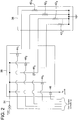
- the ballast load 38 includes a plurality of resistive elements 42 1 , 42 2 ,...42 n coupled in parallel with one another.
- the control module 36 implements a series of control switches 44 1 , 44 2 ,...44 n , each coupled to an individual resistive element of ballast load 38 to control the power flow thereto. The control of these individual switches comes from the system controller 22 as discussed above.
- system controller 22 commands additional control switches to close, thereby effectively reducing the impedance provided by ballast load 38 to thereby increase the current flow from generator 16. Conversely, when system controller 22 requires that the electrical load be reduced, it commands an appropriate number of control switches 34 to open such that the effective impedance provided by ballast load 38 increases, thereby decreasing the electrical current that is sourced by the generator 16.
- the value of the resistive elements may be identical, or they may be scaled to allow more precise control of the output power.
- the control module 36 also includes a controlled switch 46 that may be used to connect and isolate the flow of power 34 to the utilization equipment load 40 based on the power quality and the operational profile sensed by the system controller 22.
- a controlled switch 46 may be used to connect and isolate the flow of power 34 to the utilization equipment load 40 based on the power quality and the operational profile sensed by the system controller 22.
- FIG. 2 illustrates the ballast load 38 as including only resistive elements, that the actual impedance of these elements may include reactive components if desired to compensate for the impedance of the utilization equipment load 40, or for other reasons as desired or appropriate.
- FIG. 2 illustrates the controlled switches 44 of control module 36 as being insulated gate bipolar transistors (IGBTs), one skilled in the art will recognize that these control switches may take other forms as appropriate or desired, including GTOs, MOSFETs, back to back silicon controlled rectifiers (SCRs), etc.
- remotely controlled electro-mechanical devices such as remote control circuit breakers (RCCBs) or relays may also be used in this embodiment if the switching speed of these devices is sufficient to maintain power quality standards.
- RRCBs remote control circuit breakers
- the use of such slower switching mechanical type devices may not be appropriate when the utilization equipment load 40 is a switched type load such as, for example, a radar. With such loads, rapid adjustment to the amount of ballast load provided is needed in response to the switched utilization equipment load turning on and off.
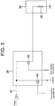
- control module 36 includes only a single controlled switching element 48 that selectively couples and decouples the electric power 34 to a single element 50 in the ballast load 38.
- control from system controller 22 is a pulse width modulated (PWM) control signal that effectively increases or decreases the amount of electrical load coupled to generator 16. That is, as the amount of electrical load needs to be increased, the system controller 22 increases the duty cycle of the PWM control signal to switching element 48, which effectively increases the amount of load supplied by generator 16.
- PWM pulse width modulated
- switching element 48 is illustrated as an IGBT, other electronic switching components may be employed, provided their switching characteristics and current carrying capacity are acceptable based on the actual loading requirements of the system.
- FIG. 4 illustrates an entire cooling and power system incorporating the instant invention.
- the system 10 in this exemplary application operates at high speed to reduce the overall weight of the system. Because of the criticality of this exemplary system, it must be highly reliable with a minimized requirement for maintenance. Therefore, magnetic bearings 52 are used in a preferred embodiment to support the turbo-machinery shaft 24 because they enhance the overall reliability of the system 10 and because they are ideal for high-speed turbo-machinery applications. The power for these magnetic bearings is also derived by the generator 16, once the expansion turbine 14 reaches a minimum operational speed.
- the structure and control of these magnetic bearings 52 are described in co-pending Application No. WO 03/019785 , entitled Permanent Magnet Turbo-Generator Having Magnetic Bearings, filed on even date herewith, the teachings and disclosure of which are hereby incorporated in their entireties herein by reference thereto.
- the system 10 provides both cold air for a radar PAO cooling loop 30 and electrical power for the radar 40.
- the system is essentially self-contained except for the gas connection 12, a start-up/shut-down electric power connection and a hot air exhaust.
- the turbo-generator system includes five separate line-replaceable units (LRUs), including the turbo-generator18, the magnetic bearing controller 54, the system controller 22, the ballast load control module 36, and the ballast load module 38.
- LRUs line-replaceable units
- the turbo-generator 18 is a radial inflow turbine 14 and with a permanent magnet generator 16.
- the turbine 14 and generator 16 are mounted on a single shaft 24 that is supported by magnetic bearings 52.
- the machine 18 includes rotor containment for the high-energy rotors.
- the magnetic bearing center section uses an axial split feature to allow replacement of the shaft and wheel assembly using common hand tools, thereby providing for high maintainability. This dramatically reduces overhaul time if service is required.
- the turbo-generator 18 uses a dual area nozzle turbine to reduce gas consumption when cooling demand and gas conditions permit.
- the generator 16 in one embodiment is a permanent magnet design.
- This brushless AC generator includes a permanent magnetic rotor and two, three-phase windings, 30° displaced, wound on a stator.
- the magnetic flux from the PMG rotor induces voltage in the stator winding when its flux sweeps the stator.
- the magnitude of the AC voltage depends upon the rotor and stator geometry, materials, and speed. With the rotor and stator geometry and materials selected, the AC voltage becomes directly proportional to the rotor speed.
- the generator air gaps are coordinated with the magnetic bearing air gaps to provide stable operation during start-up and full load operation.
- the turbo-generator shaft 24 is supported by active magnetic bearings 52 to provide optimum stiffness and damping characteristics for desired rotor dynamic response at all operating speeds and specified environmental conditions from rest to maximum design speed.
- the magnetic bearings 52 will provide long, maintenance-free life and improved overall efficiency. Initial power for the magnetic bearings is supplied from the aircraft power system. However, once the turbo-generator system reaches operational speed, this power is supplied by the permanent magnet generator 16. Backup bearings (not shown) are also incorporated to provide shaft support after shutdown and for limited periods during operation in case of electrical power supply or controller malfunction.
- the system controller 22 houses the necessary electronic circuitry to control the phase angle firing of the power conditioning and ballast load control unit's switches, and to provide system protection features such as overvoltage/undervoltage, overload protection, etc. as discussed above.
- the system controller regulates the output of the generator to provide power to the radar, and provides magnetic bearing and control power. Other loads may be supplied as needed or desired in other embodiments.
- the system controller 22 is used to control the overall system operation including valve operation, generator operation, magnetic bearing operation, PAO temperature control, and failure detection and reporting.
- the controller hardware preferably utilizes a digital system controller.
Landscapes
- Engineering & Computer Science (AREA)
- Chemical & Material Sciences (AREA)
- Combustion & Propulsion (AREA)
- Mechanical Engineering (AREA)
- General Engineering & Computer Science (AREA)
- Power Engineering (AREA)
- Health & Medical Sciences (AREA)
- General Health & Medical Sciences (AREA)
- Pulmonology (AREA)
- Aviation & Aerospace Engineering (AREA)
- Control Of Eletrric Generators (AREA)
Claims (8)
- Verfahren zum Bereitstellen gesteuerter Turbinenbelastung in einem turbogeneratorbasierten Kühlsystem (10) für ein Flugzeug, das folgende Schritte umfasst:Überwachen einer Ausgangsspannung des Turbogenerators (18);selektives Koppeln eines Ballastwiderstands (38) mit einer elektrischen Ausgangsleistung (34) des Turbogenerators (18), um die Ausgangsspannung auf einem vorbestimmten Niveau zu halten; und Steuern der Kopplung der Ausgangsleistung mit dem Ballastwiderstand in Abstimmung mit dem Kühlbedarf des Systems;wobei der Ballastwiderstand (38) mehrere parallel gekoppelte Ballastwiderstandselemente (42) umfasst, undwobei der Schritt des selektiven Koppelns des Ballastwiderstands (38) einen Schritt des Erhöhens des Ballastwiderstands (38) durch Koppeln von mindestens einem zusätzlichen Ballastwiderstandselement (42) mit der elektrischen Ausgangsleistung (34) des Turbogenerators (18) oder einen Schritt des Verringerns des Ballastwiderstands (38) durch Trennen von mindestens einem der Ballastwiderstandselemente (42) von der elektrischen Ausgangsleistung (34) des Turbogenerators (18) umfasst.
- Verfahren nach Anspruch 1, wobei der Schritt des selektiven Koppelns des Ballastwiderstands den Schritt des Erhöhens des Ballastwiderstands (38) als Reaktion auf einen Anstieg der Ausgangsspannung des Turbogenerators (18) oder Verringern des Ballastwiderstands (38) als Reaktion auf eine Abnahme der Ausgangsspannung des Turbogenerators (18) umfasst.
- Verfahren nach Anspruch 1 oder Anspruch 2, wobei der Schritt des selektiven Koppelns des Ballastwiderstands den Schritt des Verringerns des Ballastwiderstands (38) als Reaktion auf einen Anstieg des Leistungsbedarfs des Turbogenerators (18) durch damit gekoppelte Abnehmereinrichtungen (40), oder Erhöhens des Ballastwiderstands (38) als Reaktion auf eine Abnahme des Leistungsbedarfs des Turbogenerators (18) durch damit gekoppelte Abnehmereinrichtungen (40) umfasst.
- Verfahren nach einem der Ansprüche 1 bis 3, wobei der Schritt des selektiven Koppelns des Ballastwiderstands den Schritt des Erhöhens des Ballastwiderstands (38) als Reaktion auf einen Anstieg von in eine Turbine (14) des Turbogenerators (18) einströmender Luft oder Verringerns des Ballastwiderstands (38) als Reaktion auf eine Abnahme von in die Turbine (14) des Turbogenerators (18) einströmender Luft umfasst.
- Ballastwiderstandvorrichtung zur Verwendung mit einem Turbogenerator (18), der einen Teil eines Kühlsystems für ein Flugzeug bildet, wobei der Turbogenerator eine gasbetriebene Turbine (14) aufweist, die antreibbar mit einem Stromerzeuger (16) verbunden ist, wobei der Stromerzeuger (16) bei Betrieb der Turbine (14) eine elektrische Ausgangsleistung erzeugt, umfassend:ein Ballastwiderstandmodul (38);ein Steuermodul (36), das einen Eingang zum Empfangen der elektrischen Ausgangsleistung (34) des Erzeugers (16) und einen mit dem Ballastwiderstandmodul (38) gekoppelten Ausgang aufweist; undeine Systemsteuerung (22), die einen ersten sensorischen Eingang zum Abtasten der elektrischen Ausgangsleistung (34) des Erzeugers (16) und Mittel umfasst, um dem Steuermodul (36) zu befehlen, das Ballastwiderstandmodul (38) mit der elektrischen Ausgangsleistung (34) des Erzeugers (16) selektiv zu koppeln und dadurch einen elektrischen Widerstand, der mit dem Erzeuger (16) verbunden ist, zu variieren, um die elektrische Ausgangsleistung (34) des Erzeugers (16) auf einem vorbestimmten Niveau zu halten; wobei die Ausgangsleistung des Erzeugers geregelt wird, um die Turbinenlast zu steuern, und die Steuerung (22) die Kopplung der Ausgangsleistung mit dem Ballastwiderstand auf den Kühlbedarf des Systems abstimmt;wobei das Ballastwiderstandmodul (38) mehrere parallele Widerstandselemente (42) umfasst, und wobei das Steuermodul (36) mehrere parallele Schaltelemente (44) umfasst, die mit den mehreren parallelen Widerstandselementen (42) verbunden sind.
- Ballastwiderstandvorrichtung nach Anspruch 5, wobei das Steuermodul (36) ferner einen zweiten Ausgang beinhaltet, der dafür ausgelegt ist, damit verbundene Abnehmereinrichtungen (40) mit elektrischer Leistung zu versorgen.
- Kühl- und Stromerzeugungsvorrichtung, umfassend:einen Turbogenerator (18), der eine gasbetriebene Turbine (14) aufweist, die antreibbar mit einem Stromerzeuger (16) gekoppelt ist, wobei der Stromerzeuger (16) bei Betrieb der Turbine (14) eine elektrische Ausgangsleistung erzeugt, wobei die Turbine (14) eine Temperatur des Gases reduziert; und eine Ballastwiderstandvorrichtung nach einem der Ansprüche 5 oder 6.
- Kühl- und Stromerzeugungsvorrichtung nach Anspruch 7, die ferner ein Eingangsgas-Modulationsventil (20) umfasst, das durch die Systemsteuerung (22) steuerbar ist, um eine durch die Turbine (14) bereitgestellte Kühlmenge zu variieren.
Applications Claiming Priority (3)
| Application Number | Priority Date | Filing Date | Title |
|---|---|---|---|
| US939236 | 1992-09-10 | ||
| US09/939,236 US6545373B1 (en) | 2001-08-24 | 2001-08-24 | System and method for providing ballast loading for a turbo-generator |
| PCT/US2002/027054 WO2003019767A1 (en) | 2001-08-24 | 2002-08-23 | System and method for providing ballast loading for a turbo-generator |
Publications (3)
| Publication Number | Publication Date |
|---|---|
| EP1430593A1 EP1430593A1 (de) | 2004-06-23 |
| EP1430593A4 EP1430593A4 (de) | 2010-06-02 |
| EP1430593B1 true EP1430593B1 (de) | 2017-05-17 |
Family
ID=25472791
Family Applications (1)
| Application Number | Title | Priority Date | Filing Date |
|---|---|---|---|
| EP02763524.2A Expired - Lifetime EP1430593B1 (de) | 2001-08-24 | 2002-08-23 | System und verfahren zur bereitstellung eines ballasts für einen turbogenerator |
Country Status (4)
| Country | Link |
|---|---|
| US (1) | US6545373B1 (de) |
| EP (1) | EP1430593B1 (de) |
| JP (1) | JP4499413B2 (de) |
| WO (1) | WO2003019767A1 (de) |
Families Citing this family (31)
| Publication number | Priority date | Publication date | Assignee | Title |
|---|---|---|---|---|
| US7081696B2 (en) | 2004-08-12 | 2006-07-25 | Exro Technologies Inc. | Polyphasic multi-coil generator |
| US20060137664A1 (en) * | 2004-12-23 | 2006-06-29 | Mccoy Todd A | Supercharger |
| CN102647058A (zh) | 2006-06-08 | 2012-08-22 | Exro技术公司 | 电力设备 |
| GB2451703B (en) * | 2007-08-10 | 2012-09-26 | Bowman Power Group Ltd | A method of operation of an electric turbocompounding system |
| US8019522B2 (en) * | 2008-09-30 | 2011-09-13 | General Electric Company | Method and system for providing cooling and power |
| US10000293B2 (en) | 2015-01-23 | 2018-06-19 | General Electric Company | Gas-electric propulsion system for an aircraft |
| US9938853B2 (en) | 2015-10-23 | 2018-04-10 | General Electric Company | Torsional damping for gas turbine engines |
| US9764848B1 (en) | 2016-03-07 | 2017-09-19 | General Electric Company | Propulsion system for an aircraft |
| EP3263866B1 (de) * | 2016-06-29 | 2019-08-07 | Airbus Operations GmbH | System und verfahren zur erzeugung von elektrischer energie in einem fahrzeug |
| US10071811B2 (en) | 2016-08-22 | 2018-09-11 | General Electric Company | Embedded electric machine |
| US10487839B2 (en) | 2016-08-22 | 2019-11-26 | General Electric Company | Embedded electric machine |
| US10093428B2 (en) | 2016-08-22 | 2018-10-09 | General Electric Company | Electric propulsion system |
| US10308366B2 (en) | 2016-08-22 | 2019-06-04 | General Electric Company | Embedded electric machine |
| US10738695B2 (en) | 2016-11-14 | 2020-08-11 | Hamilton Sunstrand Corporation | Electrically boosted regenerative bleed air system |
| US10822103B2 (en) | 2017-02-10 | 2020-11-03 | General Electric Company | Propulsor assembly for an aircraft |
| US10793281B2 (en) | 2017-02-10 | 2020-10-06 | General Electric Company | Propulsion system for an aircraft |
| US11149578B2 (en) | 2017-02-10 | 2021-10-19 | General Electric Company | Propulsion system for an aircraft |
| WO2018213919A1 (en) | 2017-05-23 | 2018-11-29 | Dpm Technologies Inc. | Variable coil configuration system control, apparatus and method |
| US10762726B2 (en) | 2017-06-13 | 2020-09-01 | General Electric Company | Hybrid-electric propulsion system for an aircraft |
| FR3070057B1 (fr) * | 2017-08-11 | 2019-09-06 | Safran Aircraft Engines | Unite de commande d'une vanne commandee de prelevement d'un flux d'air dans un flux d'air sous pression d'un aeronef |
| EP3460206A1 (de) | 2017-09-21 | 2019-03-27 | Siemens Aktiengesellschaft | Verfahren zum betreiben einer dampfturbine |
| US11156128B2 (en) | 2018-08-22 | 2021-10-26 | General Electric Company | Embedded electric machine |
| US20210249981A1 (en) | 2018-09-05 | 2021-08-12 | Dpm Technologies Inc. | Systems and methods for intelligent control of rotating electric machines |
| US11097849B2 (en) | 2018-09-10 | 2021-08-24 | General Electric Company | Aircraft having an aft engine |
| EP3868669B1 (de) * | 2018-10-18 | 2025-09-10 | IHI Corporation | Energierückgewinnungsvorrichtung für flugzeug |
| US11722026B2 (en) | 2019-04-23 | 2023-08-08 | Dpm Technologies Inc. | Fault tolerant rotating electric machine |
| US11539316B2 (en) | 2019-07-30 | 2022-12-27 | General Electric Company | Active stability control of compression systems utilizing electric machines |
| US11897362B2 (en) | 2021-05-04 | 2024-02-13 | Exro Technologies Inc. | Systems and methods for individual control of a plurality of controllable units of battery cells |
| CN117337545A (zh) | 2021-05-13 | 2024-01-02 | Exro技术公司 | 驱动多相电机的线圈的方法及装置 |
| US12149154B2 (en) | 2021-07-22 | 2024-11-19 | General Electric Company | Electric machine having a hybrid insulative-conductive manifold |
| US20230373644A1 (en) * | 2022-05-23 | 2023-11-23 | Hamilton Sundstrand Corporation | Vapor compression system for aerospace applications |
Family Cites Families (15)
| Publication number | Priority date | Publication date | Assignee | Title |
|---|---|---|---|---|
| US3724214A (en) * | 1971-03-05 | 1973-04-03 | Westinghouse Electric Corp | Extraction control system for a turbogenerator set |
| US4455614A (en) * | 1973-09-21 | 1984-06-19 | Westinghouse Electric Corp. | Gas turbine and steam turbine combined cycle electric power generating plant having a coordinated and hybridized control system and an improved factory based method for making and testing combined cycle and other power plants and control systems therefor |
| US4005581A (en) * | 1975-01-24 | 1977-02-01 | Westinghouse Electric Corporation | Method and apparatus for controlling a steam turbine |
| US4302715A (en) * | 1979-06-15 | 1981-11-24 | Westinghouse Electric Corp. | Dynamic parallel inductive stabilizer for synchronous machines having torsional oscillations |
| US4311253A (en) * | 1979-09-14 | 1982-01-19 | Westinghouse Electric Corp. | Low loss stabilizer |
| JPS5849096A (ja) * | 1981-09-18 | 1983-03-23 | Hitachi Ltd | 風力発電装置 |
| JPH01168518A (ja) * | 1987-12-22 | 1989-07-04 | Nippon Denso Co Ltd | 車両用冷凍装置 |
| JPH0591798A (ja) * | 1991-09-25 | 1993-04-09 | Mitsubishi Electric Corp | 電力変換装置 |
| IL100172A (en) * | 1991-11-27 | 1995-12-08 | Tat Aero Equipment Ind Ltd | Air conditioning system |
| US6031294A (en) * | 1998-01-05 | 2000-02-29 | Capstone Turbine Corporation | Turbogenerator/motor controller with ancillary energy storage/discharge |
| US6058715A (en) | 1997-12-09 | 2000-05-09 | Alliedsignal Inc. | Environmental control system including air cycle machine and electrical machine |
| US6265786B1 (en) * | 1998-01-05 | 2001-07-24 | Capstone Turbine Corporation | Turbogenerator power control system |
| US6274945B1 (en) * | 1999-12-13 | 2001-08-14 | Capstone Turbine Corporation | Combustion control method and system |
| US6355987B1 (en) * | 2000-06-27 | 2002-03-12 | General Electric Company | Power converter and control for microturbine |
| US6410992B1 (en) * | 2000-08-23 | 2002-06-25 | Capstone Turbine Corporation | System and method for dual mode control of a turbogenerator/motor |
-
2001
- 2001-08-24 US US09/939,236 patent/US6545373B1/en not_active Expired - Lifetime
-
2002
- 2002-08-23 EP EP02763524.2A patent/EP1430593B1/de not_active Expired - Lifetime
- 2002-08-23 JP JP2003524104A patent/JP4499413B2/ja not_active Expired - Fee Related
- 2002-08-23 WO PCT/US2002/027054 patent/WO2003019767A1/en not_active Ceased
Also Published As
| Publication number | Publication date |
|---|---|
| WO2003019767A1 (en) | 2003-03-06 |
| JP4499413B2 (ja) | 2010-07-07 |
| US6545373B1 (en) | 2003-04-08 |
| EP1430593A4 (de) | 2010-06-02 |
| JP2005501498A (ja) | 2005-01-13 |
| US20030052652A1 (en) | 2003-03-20 |
| EP1430593A1 (de) | 2004-06-23 |
| WO2003019767A8 (en) | 2003-04-24 |
Similar Documents
| Publication | Publication Date | Title |
|---|---|---|
| EP1430593B1 (de) | System und verfahren zur bereitstellung eines ballasts für einen turbogenerator | |
| JP3793529B2 (ja) | 磁気結合式一体化電力/冷却ユニット | |
| US6093975A (en) | Turbogenerator/motor control with synchronous condenser | |
| US6031294A (en) | Turbogenerator/motor controller with ancillary energy storage/discharge | |
| US6194794B1 (en) | Integrated reciprocating engine generator set and turbogenerator system and method | |
| CA2680644C (en) | Method and system for providing cooling and power | |
| EP1826897B1 (de) | Adaptives Steuerverfahren zum Inbetriebsetzen von Elektroantrieben | |
| CA2672804C (en) | Method and apparatus for an electrical bus leveling unit | |
| EP2801719A1 (de) | Elektrisches Bordsystem in einem Flugzeug | |
| Ganev et al. | Power and thermal management for future aircraft | |
| US9917544B2 (en) | Method and power converter unit for operating a generator | |
| EP0234055A2 (de) | Verfahren und Vorrichtung zum Starten eines Triebwerks | |
| JP4685518B2 (ja) | 排熱発電設備 | |
| Morioka et al. | Thermal management system concept with an autonomous air-cooled system | |
| Yu et al. | Next generation power and thermal management system | |
| Oyori et al. | Conceptual study of low-pressure spool-generating architecture for more electric aircraft | |
| Nims | Armor-plated auxiliary power | |
| EP3907393B1 (de) | Wärmemanagementsystem und verfahren zur verwendung | |
| JP7014305B2 (ja) | 航空機用エネルギ回収装置 | |
| Verma et al. | Making the leap to electric motors and adjustable-speed drives: A case study of a 20,000-HP gas turbine-driven compressor | |
| KR100206657B1 (ko) | 발전기 냉각장치 | |
| Cronbach | Rectified-alternating-current generating systems in aircraft | |
| Mintz et al. | Design Considerations for the Supersonic Transport Electric Power System | |
| Oyori et al. | Integrated power management system for the More Electric Aircraft | |
| Goldberg | Generators inside small engines |
Legal Events
| Date | Code | Title | Description |
|---|---|---|---|
| PUAI | Public reference made under article 153(3) epc to a published international application that has entered the european phase |
Free format text: ORIGINAL CODE: 0009012 |
|
| 17P | Request for examination filed |
Effective date: 20040320 |
|
| AK | Designated contracting states |
Kind code of ref document: A1 Designated state(s): AT BE BG CH CY CZ DE DK EE ES FI FR GB GR IE IT LI LU MC NL PT SE SK TR |
|
| AX | Request for extension of the european patent |
Extension state: AL LT LV MK RO SI |
|
| RAP1 | Party data changed (applicant data changed or rights of an application transferred) |
Owner name: GE AVIATION SYSTEMS LLC |
|
| A4 | Supplementary search report drawn up and despatched |
Effective date: 20100503 |
|
| RIC1 | Information provided on ipc code assigned before grant |
Ipc: F02C 6/08 20060101ALI20100426BHEP Ipc: B64D 13/06 20060101AFI20100426BHEP Ipc: F01D 15/10 20060101ALI20100426BHEP Ipc: F02C 7/32 20060101ALI20100426BHEP Ipc: H02P 9/04 20060101ALI20100426BHEP |
|
| 17Q | First examination report despatched |
Effective date: 20100722 |
|
| GRAP | Despatch of communication of intention to grant a patent |
Free format text: ORIGINAL CODE: EPIDOSNIGR1 |
|
| RBV | Designated contracting states (corrected) |
Designated state(s): DE FR GB |
|
| INTG | Intention to grant announced |
Effective date: 20170124 |
|
| GRAS | Grant fee paid |
Free format text: ORIGINAL CODE: EPIDOSNIGR3 |
|
| GRAA | (expected) grant |
Free format text: ORIGINAL CODE: 0009210 |
|
| AK | Designated contracting states |
Kind code of ref document: B1 Designated state(s): DE FR GB |
|
| REG | Reference to a national code |
Ref country code: GB Ref legal event code: FG4D |
|
| REG | Reference to a national code |
Ref country code: DE Ref legal event code: R096 Ref document number: 60248884 Country of ref document: DE |
|
| REG | Reference to a national code |
Ref country code: FR Ref legal event code: PLFP Year of fee payment: 16 |
|
| REG | Reference to a national code |
Ref country code: DE Ref legal event code: R097 Ref document number: 60248884 Country of ref document: DE |
|
| PLBE | No opposition filed within time limit |
Free format text: ORIGINAL CODE: 0009261 |
|
| STAA | Information on the status of an ep patent application or granted ep patent |
Free format text: STATUS: NO OPPOSITION FILED WITHIN TIME LIMIT |
|
| 26N | No opposition filed |
Effective date: 20180220 |
|
| REG | Reference to a national code |
Ref country code: FR Ref legal event code: PLFP Year of fee payment: 17 |
|
| PGFP | Annual fee paid to national office [announced via postgrant information from national office to epo] |
Ref country code: FR Payment date: 20210722 Year of fee payment: 20 |
|
| PGFP | Annual fee paid to national office [announced via postgrant information from national office to epo] |
Ref country code: GB Payment date: 20210720 Year of fee payment: 20 Ref country code: DE Payment date: 20210720 Year of fee payment: 20 |
|
| REG | Reference to a national code |
Ref country code: DE Ref legal event code: R071 Ref document number: 60248884 Country of ref document: DE |
|
| REG | Reference to a national code |
Ref country code: GB Ref legal event code: PE20 Expiry date: 20220822 |
|
| PG25 | Lapsed in a contracting state [announced via postgrant information from national office to epo] |
Ref country code: GB Free format text: LAPSE BECAUSE OF EXPIRATION OF PROTECTION Effective date: 20220822 |
|
| P01 | Opt-out of the competence of the unified patent court (upc) registered |
Effective date: 20230414 |