EP1430937A1 - Elément d'espacement - Google Patents
Elément d'espacement Download PDFInfo
- Publication number
- EP1430937A1 EP1430937A1 EP04007534A EP04007534A EP1430937A1 EP 1430937 A1 EP1430937 A1 EP 1430937A1 EP 04007534 A EP04007534 A EP 04007534A EP 04007534 A EP04007534 A EP 04007534A EP 1430937 A1 EP1430937 A1 EP 1430937A1
- Authority
- EP
- European Patent Office
- Prior art keywords
- snowboard
- spacer
- side parts
- binding
- boot
- Prior art date
- Legal status (The legal status is an assumption and is not a legal conclusion. Google has not performed a legal analysis and makes no representation as to the accuracy of the status listed.)
- Withdrawn
Links
- 125000006850 spacer group Chemical group 0.000 title claims abstract description 100
- 230000027455 binding Effects 0.000 claims abstract description 73
- 238000009739 binding Methods 0.000 claims abstract description 73
- 239000000463 material Substances 0.000 claims description 16
- 238000013016 damping Methods 0.000 claims description 7
- 229920002430 Fibre-reinforced plastic Polymers 0.000 claims description 2
- 239000011151 fibre-reinforced plastic Substances 0.000 claims description 2
- 239000006260 foam Substances 0.000 claims description 2
- 239000002184 metal Substances 0.000 claims description 2
- 229910052751 metal Inorganic materials 0.000 claims description 2
- 239000004033 plastic Substances 0.000 claims description 2
- 229920003023 plastic Polymers 0.000 claims description 2
- 230000003014 reinforcing effect Effects 0.000 claims description 2
- 230000005540 biological transmission Effects 0.000 description 3
- 238000010276 construction Methods 0.000 description 3
- 230000035939 shock Effects 0.000 description 3
- 230000000694 effects Effects 0.000 description 2
- 229920001971 elastomer Polymers 0.000 description 2
- 239000004952 Polyamide Substances 0.000 description 1
- 238000010521 absorption reaction Methods 0.000 description 1
- 230000002411 adverse Effects 0.000 description 1
- 238000006243 chemical reaction Methods 0.000 description 1
- 230000006378 damage Effects 0.000 description 1
- 230000003111 delayed effect Effects 0.000 description 1
- 230000001419 dependent effect Effects 0.000 description 1
- 238000006073 displacement reaction Methods 0.000 description 1
- 239000000806 elastomer Substances 0.000 description 1
- 229920001821 foam rubber Polymers 0.000 description 1
- 230000003993 interaction Effects 0.000 description 1
- 150000002739 metals Chemical class 0.000 description 1
- 230000007935 neutral effect Effects 0.000 description 1
- 230000003094 perturbing effect Effects 0.000 description 1
- 229920002647 polyamide Polymers 0.000 description 1
- 229920000515 polycarbonate Polymers 0.000 description 1
- 239000004417 polycarbonate Substances 0.000 description 1
- 229920002635 polyurethane Polymers 0.000 description 1
- 239000004814 polyurethane Substances 0.000 description 1
- 230000008092 positive effect Effects 0.000 description 1
- 239000005060 rubber Substances 0.000 description 1
- 230000003068 static effect Effects 0.000 description 1
Images



Classifications
-
- A—HUMAN NECESSITIES
- A63—SPORTS; GAMES; AMUSEMENTS
- A63C—SKATES; SKIS; ROLLER SKATES; DESIGN OR LAYOUT OF COURTS, RINKS OR THE LIKE
- A63C10/00—Snowboard bindings
- A63C10/26—Shock or vibration dampers
-
- A—HUMAN NECESSITIES
- A63—SPORTS; GAMES; AMUSEMENTS
- A63C—SKATES; SKIS; ROLLER SKATES; DESIGN OR LAYOUT OF COURTS, RINKS OR THE LIKE
- A63C10/00—Snowboard bindings
- A63C10/14—Interfaces, e.g. in the shape of a plate
-
- A—HUMAN NECESSITIES
- A63—SPORTS; GAMES; AMUSEMENTS
- A63C—SKATES; SKIS; ROLLER SKATES; DESIGN OR LAYOUT OF COURTS, RINKS OR THE LIKE
- A63C10/00—Snowboard bindings
- A63C10/16—Systems for adjusting the direction or position of the bindings
- A63C10/18—Systems for adjusting the direction or position of the bindings about a vertical rotation axis relative to the board
-
- A—HUMAN NECESSITIES
- A63—SPORTS; GAMES; AMUSEMENTS
- A63C—SKATES; SKIS; ROLLER SKATES; DESIGN OR LAYOUT OF COURTS, RINKS OR THE LIKE
- A63C10/00—Snowboard bindings
- A63C10/16—Systems for adjusting the direction or position of the bindings
- A63C10/20—Systems for adjusting the direction or position of the bindings in longitudinal or lateral direction relative to the board
-
- A—HUMAN NECESSITIES
- A63—SPORTS; GAMES; AMUSEMENTS
- A63C—SKATES; SKIS; ROLLER SKATES; DESIGN OR LAYOUT OF COURTS, RINKS OR THE LIKE
- A63C10/00—Snowboard bindings
- A63C10/28—Snowboard bindings characterised by auxiliary devices or arrangements on the bindings
- A63C10/285—Pads as foot or binding supports, e.g. pads made of foam
Definitions
- the present invention relates to a spacer and a screw extension for Snowboard bindings according to the preamble of the independent claims.
- the bindings common today are usually by means of screws in the middle of the Snowboards fastened in the screw inserts provided.
- the forces are on few, limited places between snowboard and binding.
- the control forces typically act on the edge areas of a snowboard. she are in turn in balance with the driver's corresponding reaction forces, which are mainly transmitted at the toe and heel of the snowboard boot.
- these forces due to Art and manner of construction, beyond the few, narrowly limited and in the middle of the Transfer snowboards lying attachment points. This contradicts the fact that the Areas in which the forces are generated, namely the top and the heel of the Snowboard boots, and the areas where the forces are transferred to the ground will be, namely the edge areas of the snowboard, directly one above the other.
- a snowboard binding is known from CH 677 191. This consists of one element which is connected to the snowboard via a central attachment.
- PCT / EP96 / 02980 discloses another binding for snowboards in which also the Attachment and thus the transfer of forces between snowboard and rider in the middle of the snowboard.
- a binding for snowboards is known from FR 2 740 983, the base plate of which is directly on the Snowboard is attached. The power is transmitted in the middle of the snowboard.
- US 5,520,405 shows another binding for snowboards with a bayonet lock.
- the snowboard boots have supports at the back and front that serve as walking aids.
- the invention disclosed here consists of a spacer, which in combination with the known snowboards and snowboard bindings is used with the different Connections is compatible and solves the problems inherent in the prior art.
- the Spacer is designed so that it is not dependent on a single type of binding and can be easily used with multiple types of bindings.
- the spacer is in active combination with the snowboard and / or the Snowboard binding and / or the snowboard boot, so that the resulting forces are optimal be transmitted between the place of their origin and the place of action.
- the spacer in the area of the binding plate is the footprint for the Snowboard boots, especially on narrow snowboards or on snowboards that are on the Have tops in some areas, specifically enlarged and on the other hand the Distance between snowboard boots and snowboard increased in an advantageous manner. This causes u. a. a better load transfer into the snowboard, resp. the snowboard boots, and enables better pressure build-up between edges and, especially when cornering Underground.
- the feedback from the snowboard respectively. the interaction between driver and Snowboard is specifically improved.
- the angle can be used to guarantee an ergonomic, natural foot position between the standing surface for the snowboard boots and the sliding surface of the snowboard if necessary be adjusted. This ensures that the various driving habits and styles are optimal Considered and the risk of cramping is reduced to a minimum.
- the spacer disclosed here makes it necessary for driving the snowboard Strictly reduced effort because of the increased distance between the snowboard and the snowboard boots on the one hand and the increased footprint on the other, the effective one Lever arm for power transmission increases, resulting in an increase in effective steering forces leads. This has a particularly positive effect on the driving characteristics.
- Another function of The invention disclosed here is a better cushioning between snowboard boots and Snowboard. This leads to targeted shocks and vibrations that are harmful to the driver be reduced and the snowboard tends to flutter less when driving fast. The driver this gives a safe driving experience, as there is always direct contact between Snowboard and rider is guaranteed.
- the load transfer into the snowboard is, in contrast to State of the art is no longer limited to a few places, but takes place according to the invention area.
- the spacer preferably behaves as possible neutral to the stiffness of the snowboard and therefore acts, in contrast to the Today, sometimes very hard, binding plates, checked for rigidity.
- the spacer disclosed here is advantageously multi-part and adjustable, so that a Compatibility with various snowboards and snowboards available on the market Snowboard bindings is achieved.
- the individual parts can, after loosening certain Fasteners, move against each other in a defined area and so the adapt to specific requirements and driving habits. This will make one achieved the greatest possible independence from the desired board or binding type.
- This Adaptability to different board and binding types is done in particular by Moving the parts whereby the width of the spacer is variable to the board width of different snowboards, e.g. Freestyle or Alpine boards, is customizable.
- the Spacers compatible with the standard hole patterns of snowboard bindings such as 4x4 and 3x3, as well as with common connection surfaces of Soft, Alpine and Stepin bindings.
- the spacer is also suitable for, in particular due to the multiple parts and the adaptability Suitable snowboards that have no flat surface on the top.
- a preferred embodiment of the invention relates to a snowboard binding type independent Spacer for a snowboard, the middle part with means for fastening of different commercial snowboard bindings with the snowboard.
- the fasteners are designed so that the snowboard for fastening the Snowboard binding provided fasteners with the on the snowboard bindings provided fasteners are operatively connected.
- Side parts as spacers between a snowboard and a snowboard boot in such a way that they connect between the top of the snowboard boot and the snowboard, respectively. the paragraph of the Snowboard boots and the snowboard result.
- a preferred embodiment of a spacer has one between several, movable Removable side parts arranged middle part with means for fastening.
- the middle part has means for fixing the Side parts in terms of angle, orientation and distance from the middle part adjustable positions.
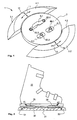
- Figure 1 shows an embodiment of a multi-part spacer 1 according to the invention in a perspective view obliquely from above.
- the spacer 1 here consists of a middle part 2 and two side parts 3.1 and 3.2 with standing surfaces 4.1 and 4.2, which preferably have a non-slip covering.
- the spacer 1 according to the invention is mounted between a snowboard boot 22 (cf. FIG. 3) and a snowboard 20 (cf. FIG. 3) in such a way that a positive connection with short load paths according to the invention results between the snowboard 20 and the snowboard boot 22.
- the side parts 3.1 and 3.2 and the middle part 2 advantageously consist of plastics (for example: polyamide, polycarbonate, polyurethane), fiber-reinforced plastics, foams, metals or similar suitable materials or combinations thereof.
- the individual parts of the spacer 1 can be made of different materials.
- the side parts 3.1 and 3.2 and / or the middle part 2 can have cutouts or reinforcing ribs or advantageously consist of layers of several materials which specifically support the damping and stability properties and contribute to material and weight savings and vibration damping.
- elastomers or equivalent materials are particularly suitable for damping shocks and vibrations.
- vibrations are advantageously damped by targeted friction, in particular between the layers.
- the spacer 1 is mounted using fastening means, preferably openings 6.1, 6.2, 6.3, which with the holes, or the hole pattern of several on the Available snowboard bindings and the thread inserts of the snowboards 20 correspond.
- fastening means preferably openings 6.1, 6.2, 6.3, which with the holes, or the hole pattern of several on the Available snowboard bindings and the thread inserts of the snowboards 20 correspond.
- a Screw extension 60.1 to 60.4 developed for mounting screws (see. Fig. 5), which the Assembly of the spacer 1 simplified.
- a possible arrangement of the Screw extensions 60.1 to 60.4 is shown schematically here.
- the side elements 3.1 and 3.2 are, when the fastening screws of the snowboard binding are loosened 21 (see FIG. 3), opposite the central part 2 in the direction of arrows 11, 12, 13 and 14 in one defined area preferably steplessly and independently displaceable.
- the spacer 1 is so targeted to the different sizes of snowboard boots 22 (see FIG. 3) and angle of the Snowboard binding 21 (see FIG. 3) is set to the direction of travel.
- the areas over which forces are transmitted to the snowboard 20 targeted discontinued or relocated.
- certain surfaces of the spacer 1 are partial or completely with an anti-slip covering or equivalent elements, so that between the Contact surfaces of the spacer 1 and the snowboard boot 22 (see FIG. 3) and / or one between the contact surfaces of the spacer 1 and the snowboard 20 (see FIG. 3) there is increased static friction. This will include getting into the Snowboard binding 21 (see FIG. 3) facilitated.
- the side parts 3.1 and 3.2 are compared to that Middle part 2 adjustable, whereby the load transfer into the snowboard 20 (see FIG. 3) becomes.
- the spacer is preferably designed so that snow is not perturbing what would adversely affect handling.
- FIG. 2 schematically shows an arrangement of a snowboard boot 22 on a snowboard 20 that is typical in the prior art today. It is a sectional view through the snowboard 20 approximately perpendicular to the direction of travel.
- a snowboard binding 21 connects the snowboard boot 22 to the snowboard 20.
- Load paths 25 and 26 show the approximate course of the forces between a tip 40 of the snowboard boot 22, or the heel 41 of the snowboard boot, and edge regions 50 and 51 of the snowboard 20 long detour of the load paths 25, 26 via the snowboard binding 21.
- FIG. 3A schematically shows a function of the spacer 1 according to the invention.
- the viewing direction corresponds to that of FIG. 2.
- the spacer 1 is designed such that it can be integrated between the snowboard binding 21, the snowboard boot 22 and the snowboard 20 as a non-positive connection.
- the addition of the spacer 1 enlarges the standing areas and the areas for the load introduction into the snowboard 20.
- the now effective load paths 27 and 28 are in comparison to the load paths 25 and 26 shown in FIG. 2, very short and adjustable.
- the control forces are intentionally directed from their point of origin, tip 40, or the heel 41 of the snowboard boot 22, to their destination, namely the edge regions 50 and 51 of the snowboard 20.
- the material of the spacer 1 specifically influences the forces transmitted via the load paths 27 and 28. On the one hand, they are better distributed and introduced into the snowboard 20 over a larger area, but on the other hand they are also dampened. As a result, the shocks and vibrations which are harmful to the driver and the material are deliberately influenced, in contrast to the arrangement without a spacer 1 (according to FIG. 2).
- the impacts and the vibrations of the snowboard 20 are changed by the choice of the materials for the individual parts of the spacer 1 and their combination.
- Two types of friction are advantageously used. External friction on the one hand and internal friction on the other. External friction is understood to mean friction between various contact surfaces provided for this purpose, in particular in the case of layered construction. Internal friction means the destruction of kinetic energy in suitable materials. Elastomeric or functionally equivalent materials are particularly suitable for this.
- the load paths 27 and 28 according to the invention can also be different than shown here run. In any case, they pass through the spacer 1 in whole or in part.
- the Non-positive connection between snowboard boots 22 and snowboard 20 advantageously works in Area of the tip 40 of the snowboard boot 22 and in the area of the heel 41 of the Snowboard boots 22.
- the spacer 1 increases the distance 29 between the Snowboard boots 22 and the snowboard 20. This enlargement causes about that Snowboard 20 protruding parts of the snowboard binding 21 or the snowboard boot 22 especially when cornering less tend to hang on the ground.
- the ground clearance gained thereby serves for greater inclinations in the To achieve cornering and on the other hand the effort required when driving consciously reduce, respectively. to allow a greater pressure build-up, because the effective Lever arm extended and the build-up of force in edges 50 and 51 is optimized.
- the Effect of the lever arm is adjusted via the thickness of the spacer 1.
- the Snowboard binding 21 has spacer 1 in the embodiment shown here no direct contact with the Snowboard 20.
- the spacer 1 is particularly effective snowboards that are becoming ever narrower, which improves maneuverability.
- FIG. 3B shows a further embodiment of a spacer 1.
- the spacer 1 shown here is not directly connected to the snowboard boot 22, but is operatively connected to it via the snowboard binding 21.
- the spacer 1 distributes the forces and moments transmitted to it from the snowboard binding 21 over a large area onto the snowboard 20. Due to its construction according to the invention, the spacer 1 contributes in particular to the damping and absorption of harmful and unwanted impacts and vibrations. In addition, it increases the distance 29 between snowboard 20 and snowboard boot 22.
- FIG. 4 shows a preferred embodiment of a spacer 1 with the snowboard 20, the snowboard binding 21 and the snowboard boot 22 approximately in a rear view. Only a section of the snowboard 20 is drawn, which is illustrated by the jagged ends.
- the embodiment of the spacer 1 shown here has the effect that the snowboard boot 22 is inclined at a certain angle ⁇ to a sliding surface 23 of the snowboard 20.
- the inclination of the snowboard boot 22 is not limited to a purely lateral inclination, as shown here.
- the angle ⁇ can be changed in a targeted manner so that individual needs, habits and driving styles can be satisfied. This adaptability makes it possible to achieve an ergonomic position for the rider on the snowboard 20, in which the feet assume a natural position, thereby avoiding tension.
- the angle ⁇ is defined by the geometry of the spacer 1.
- the spacer 1 is constructed in such a way that the angle ⁇ can be added at any time by adding additional elements, for example by placing wedge elements underneath (not shown in more detail), or by changing the geometry of the middle part 2 and / or the side parts 3.1 and 3.2 (not shown) is set to the desired size.
- a spherical or cylindrical mounting of the middle part 2 and / or the side parts 3.1 and 3.2 in corresponding counter bearings (not shown in more detail) is particularly suitable.
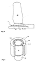
- FIG. 5 shows a preferred embodiment of a screw extension 60 which is used for mounting the spacer 1.
- This screw extension 60 serves to extend the fastening screws (not shown in more detail) for the snowboard binding 21. It bridges the distance 29 created by the spacer 1 between the snowboard boot 22 or snowboard binding 21 and the snowboard 20 (see FIG. 3).
- the screw extension 60 here consists of a pin 61 and a rotating part 65 which surrounds the pin 61.
- the rotating part 65 is designed such that it is supported on the respective threaded insert (not shown in more detail) in the snowboard 20 and protects it against being pulled out.
- the pin 61 has an external thread 62 at one end and an internal thread 63 at the other end.
- the screw extension 60 is screwed into the threaded inserts of the snowboard 20 provided for the binding assembly when the spacer 1 is mounted, so that, after the spacer 1 has been put on, a suitable hole pattern for the mounting of the snowboard binding 21 on the opposite side of the spacer 1 is again present , Grooves 64.1 and 64.2 are used to screw in the screw extension 60 using a screwdriver.
- FIG 6a shows a spacer 1 according to Figure 1 in a perspective view obliquely from above.
- the spacer 1 is mounted on a snowboard 20 in such a way that the side elements 3.1 and 3.2 ensure optimal load introduction into lateral edge areas 70.1 and 70.2.
- the side parts 3.1 and 3.2 which are adjustable in angle and distance relative to the middle part 2, ensure this with every combination of commercially available snowboards and bindings.
- a typical position of a snowboard boot (not shown in detail) is shown schematically here by a hatched area 71. Inside the hatched area 71 two densely hatched areas 72.1 and 72.2 can be seen, which are located in the area of the contact zones between the side elements 3.1 and 3.2 and a snowboard boot tip, respectively. of a snowboard boot heel.
- Figure 6b shows the spacer 1 according to Figure 6a in a view from below.
- the middle part 2 and the side elements 3.1 and 3.2 can be seen.
- the side elements 3.1 and 3.2 are here, compared to the illustration shown in Figure 1, shifted by an angle ⁇ (3.1) and a distance D (3.2).
- the parts 3.1 and 3.2 can also be locked in any other position.
- the side elements 3.1 and 3.2 have tabs 10.1 and 10.2 with openings 15.1, 15.2, 15.3 and 15.4. These tabs 10.1 and 10.2 engage under an edge 16 of the middle part 2.
- Figure 7 shows the spacer of Figure 1 from below.
- the middle part 2 and the side elements 3.1 and 3.2 symmetrically arranged here can be seen.
- the side elements 3.1 and 3.2 have cutouts 19 here. They can also be made in layers of different materials or have ribs or other elements.
- the special design and shape determine at which points a targeted load transfer into the snowboard takes place.
- the side elements 3.1 and 3.2 can advantageously be exchanged separately, so that special wishes and requirements, in particular with regard to the different snowboard binding systems and snowboards, are met.
- FIG. 8 shows a sectional view through the spacer 1 according to FIG. 7 along a section line AA which runs centrally through the elastically deformable elements 18.2 and 18.4.
- the illustration shown here shows the spacer 1 fixed on a snowboard 20.
- the fastening screws (not shown in detail) of the snowboard binding (see FIG. 1) are tightened so that the tabs 10.1 and 10.2 between the edge 16 of the middle part 2 and the surface of the Snowboards 20 are trapped.
- the openings 15.2 and 15.4 (15.1 and 15.3 equivalent) are arranged so that they lie in the effective area of the edge 16.
- the elements 18.2 and 18.4 (18.1 and 18.3 equivalent) are pressed by the edge 16 against the surface of the snowboard 20 and locked against lateral displacement.
- the side elements 3.1 and 3.2 are locked in their position.
- the adjustable areas of the side elements 3.1 and 3.2 are selected so that the independence from the type of snowboard binding and snowboard is optimally taken into account.
- the disadvantages of the snowboard bindings and snowboards known from the prior art are avoided by the combination with the spacer 1 disclosed here.
- FIG. 9 shows a further preferred embodiment of a spacer 1 in which the angle ⁇ between the snowboard boot 22 and the snowboard 20 (cf. FIG. 4) is adjustable.
- the spacer 1 is shown in a sectional view for the sake of clarity.
- the spacer 1 here consists of two side parts 3.1 and 3.2 and the middle part 2, which here consists of the two parts 2.1 and 2.2.
- the two parts 2.1 and 2.2 each have a spherical surface 8, respectively. 9 on. These two surfaces correspond to one another in such a way that the part 2.2 can be displaced relative to the part 2.1 in an unfixed state.
- the element 2.1 has a threaded opening 30 in which a fastening element (not shown in more detail), which acts on a surface 31 of the part 2.2 which is also spherical here, is anchored.
- the part 2.1 is fastened on a snowboard (not shown in more detail) via fastening means, here openings 6.1 and 6.2, analogously to the description of FIG. 1.
- a snowboard binding (not shown in more detail) is shown on part 2.2 via corresponding Fastening elements, here the openings 6.10, 6.11 and 6.12).
- Over areas 32 and 33 an active connection between a tip of a snowboard boot (not shown in more detail), respectively.
- a heel (not shown) and a snowboard (not shown in more detail).
- the spacer 1 is designed such that the angle ⁇ (cf. Figure 4) meets needs and is freely adjustable in all directions.
- the side panels 3.1 and 3.2 are attached analogously to the embodiment described in FIG.
- Figure 10 shows a spacer 1 according to Figure 1 with a commercially available shell snowboard binding 21 (sectional view).
- the side parts 3.1 and 3.2 and the middle part 2 here have the same height, so that the shell binding in particular rests securely on the side parts 3.1 and 3.2 and short load paths are guaranteed.
- the spacer 1 is designed in such a way that different side parts 3.1, 3.2 and middle parts 2 can be connected and exchanged in a manner that is compatible with one another.
- the openings 6.1, 6.2, 6.3 correspond to the openings 34.1 and 34.2 of the shell snowboard binding 21 provided as fastening means, so that secure fastening with a snowboard (not shown in more detail) is guaranteed.
- the spacer 1 can be adjusted as shown here so that no parts of the snowboard binding 21 protrude in endangered areas.
- the spacer 1 is in particular designed such that the holding straps 35.1 and 35.2, respectively.
- the middle part 2 is transferred to a snowboard binding (not shown in detail) and introduced over a large area.
Landscapes
- Footwear And Its Accessory, Manufacturing Method And Apparatuses (AREA)
- Lasers (AREA)
- Valve-Gear Or Valve Arrangements (AREA)
Applications Claiming Priority (3)
| Application Number | Priority Date | Filing Date | Title |
|---|---|---|---|
| CH238998 | 1998-12-01 | ||
| CH238998 | 1998-12-01 | ||
| EP99955630A EP1135196B1 (fr) | 1998-12-01 | 1999-11-26 | Cale |
Related Parent Applications (1)
| Application Number | Title | Priority Date | Filing Date |
|---|---|---|---|
| EP99955630A Division EP1135196B1 (fr) | 1998-12-01 | 1999-11-26 | Cale |
Publications (1)
| Publication Number | Publication Date |
|---|---|
| EP1430937A1 true EP1430937A1 (fr) | 2004-06-23 |
Family
ID=4232647
Family Applications (2)
| Application Number | Title | Priority Date | Filing Date |
|---|---|---|---|
| EP04007534A Withdrawn EP1430937A1 (fr) | 1998-12-01 | 1999-11-26 | Elément d'espacement |
| EP99955630A Expired - Lifetime EP1135196B1 (fr) | 1998-12-01 | 1999-11-26 | Cale |
Family Applications After (1)
| Application Number | Title | Priority Date | Filing Date |
|---|---|---|---|
| EP99955630A Expired - Lifetime EP1135196B1 (fr) | 1998-12-01 | 1999-11-26 | Cale |
Country Status (6)
| Country | Link |
|---|---|
| US (1) | US6505841B1 (fr) |
| EP (2) | EP1430937A1 (fr) |
| JP (1) | JP4212772B2 (fr) |
| AT (1) | ATE262961T1 (fr) |
| DE (1) | DE59909054D1 (fr) |
| WO (1) | WO2000032285A1 (fr) |
Families Citing this family (23)
| Publication number | Priority date | Publication date | Assignee | Title |
|---|---|---|---|---|
| FR2801512B1 (fr) * | 1999-11-30 | 2001-12-21 | Rossignol Sa | Plaque interface montee sur une planche de surf |
| EP1163937A3 (fr) * | 2000-06-09 | 2002-10-23 | Völkl Sports GmbH & Co. KG | Plaque de surélévation |
| EP1216729A1 (fr) * | 2000-12-22 | 2002-06-26 | Dakuga Holding Ltd. | Moyens d'entretoise pour une planche de glisse sur neige |
| US6715773B2 (en) * | 2001-01-09 | 2004-04-06 | K-2 Corporation | Adjustable damping pads for snowboard bindings |
| US20050029757A1 (en) * | 2002-02-01 | 2005-02-10 | Jon Fiebing | Swivelable mount for attaching a binding to a snowboard |
| US20050253347A1 (en) * | 2002-03-13 | 2005-11-17 | Dakuga Holding Ltd | Snowboard binding |
| US20040145155A1 (en) * | 2003-01-24 | 2004-07-29 | Dakuga Holding Ltd. | Spacer for snowboard |
| DE10313342B4 (de) * | 2003-03-25 | 2007-06-28 | Goodwell International Ltd., Tortola | Snowboardbindung |
| US20060119055A1 (en) * | 2004-12-03 | 2006-06-08 | Xzist Technology, Llc. | Adjustable span snowboard stability and dampening system |
| AT505715B1 (de) * | 2007-09-12 | 2012-02-15 | Atomic Austria Gmbh | Bindungseinrichtung für brettartige gleitgeräte |
| US8419043B2 (en) | 2007-10-22 | 2013-04-16 | William H. Bollman | Flexible ergonomic sportsboard wedges |
| US7832742B1 (en) | 2008-02-15 | 2010-11-16 | Duggan John C | Ergonomically advanced rotating boot and foot mounting system for sportboards |
| US8469372B2 (en) | 2008-10-23 | 2013-06-25 | Bryce M. Kloster | Splitboard binding apparatus |
| JP5569926B2 (ja) * | 2009-09-18 | 2014-08-13 | 株式会社ジャパーナ | スノーボード用衝撃吸収ベースプレート |
| US9238168B2 (en) | 2012-02-10 | 2016-01-19 | Bryce M. Kloster | Splitboard joining device |
| US9266010B2 (en) | 2012-06-12 | 2016-02-23 | Tyler G. Kloster | Splitboard binding with adjustable leverage devices |
| US9364738B2 (en) * | 2013-10-21 | 2016-06-14 | Henry Kim | Recreational board riser |
| US10471335B2 (en) * | 2014-07-31 | 2019-11-12 | Travis Rice | Snowboard apparatus or accessory |
| US10029165B2 (en) | 2015-04-27 | 2018-07-24 | Bryce M. Kloster | Splitboard joining device |
| US9604122B2 (en) | 2015-04-27 | 2017-03-28 | Bryce M. Kloster | Splitboard joining device |
| US10500475B2 (en) * | 2017-11-28 | 2019-12-10 | Daniel Joseph Walsh | Spacer for snowboard |
| US11117042B2 (en) | 2019-05-03 | 2021-09-14 | Bryce M. Kloster | Splitboard binding |
| US11938394B2 (en) | 2021-02-22 | 2024-03-26 | Bryce M. Kloster | Splitboard joining device |
Citations (2)
| Publication number | Priority date | Publication date | Assignee | Title |
|---|---|---|---|---|
| WO1997018016A1 (fr) * | 1995-11-15 | 1997-05-22 | Salomon S.A. | Dispositif de retenue d'une chaussure de snowboard permettant un basculement lateral de la chaussure par rapport a la planche |
| DE19619676A1 (de) * | 1996-01-08 | 1997-07-10 | Burton Corp | Verfahren und Vorrichtung zum Schrägstellen und Anheben einer Snowboardbindung |
Family Cites Families (14)
| Publication number | Priority date | Publication date | Assignee | Title |
|---|---|---|---|---|
| CH677191A5 (en) | 1988-07-14 | 1991-04-30 | Emery Soc | Adjustable boot binding for snow board |
| DE9108513U1 (de) * | 1991-07-10 | 1991-09-26 | F 2 International Ges.m.b.H., Kirchdorf | Bindung für Snowboards |
| US5188386A (en) * | 1992-02-26 | 1993-02-23 | Schweizer Russell J | Binding mounting apparatus |
| US5354088A (en) * | 1993-03-15 | 1994-10-11 | Vetter Dennis A | Boot binding coupling for snow boards |
| US5520405A (en) | 1994-08-10 | 1996-05-28 | Bourke; Lyle J. | Snowboard binding and boot including complementary opening and binding member |
| EP0841971B1 (fr) | 1995-08-02 | 2001-10-31 | Marker Deutschland GmbH | Chaussure avec fixations associees pour planches a neige ou similaires |
| US5913530A (en) * | 1996-06-25 | 1999-06-22 | Berger; Richard W. | Snowboard binding |
| US6029991A (en) * | 1997-03-13 | 2000-02-29 | Frey; Bernard M. | Impact releasable snowboard boot binding assembly and method |
| US5984343A (en) | 1997-04-08 | 1999-11-16 | Robert J. Harrington | Sliding apparatus having adjustable flexion and torsion characteristics |
| US6022041A (en) * | 1998-02-27 | 2000-02-08 | Matthew Robert Dailey | Adapter assembly for pivotable mounting of a binding to a snowboard |
| US6296258B2 (en) * | 1998-06-30 | 2001-10-02 | Polar Design | Snowboard shock-absorbing apparatus |
| US6203051B1 (en) * | 1999-03-23 | 2001-03-20 | Jeffrey P. Sabol | Safety rotatable snowboard boot binding |
| US6450511B1 (en) * | 2000-02-28 | 2002-09-17 | Lavoy Thomas F. | Snowboard binding mount assembly |
| US6318749B1 (en) * | 2000-05-08 | 2001-11-20 | Imants Eglitis | Angularly adjustable snowboard binding mount |
-
1999
- 1999-11-26 EP EP04007534A patent/EP1430937A1/fr not_active Withdrawn
- 1999-11-26 JP JP2000584970A patent/JP4212772B2/ja not_active Expired - Fee Related
- 1999-11-26 DE DE59909054T patent/DE59909054D1/de not_active Expired - Lifetime
- 1999-11-26 WO PCT/CH1999/000568 patent/WO2000032285A1/fr not_active Ceased
- 1999-11-26 AT AT99955630T patent/ATE262961T1/de not_active IP Right Cessation
- 1999-11-26 EP EP99955630A patent/EP1135196B1/fr not_active Expired - Lifetime
- 1999-11-26 US US09/857,079 patent/US6505841B1/en not_active Expired - Fee Related
Patent Citations (2)
| Publication number | Priority date | Publication date | Assignee | Title |
|---|---|---|---|---|
| WO1997018016A1 (fr) * | 1995-11-15 | 1997-05-22 | Salomon S.A. | Dispositif de retenue d'une chaussure de snowboard permettant un basculement lateral de la chaussure par rapport a la planche |
| DE19619676A1 (de) * | 1996-01-08 | 1997-07-10 | Burton Corp | Verfahren und Vorrichtung zum Schrägstellen und Anheben einer Snowboardbindung |
Also Published As
| Publication number | Publication date |
|---|---|
| DE59909054D1 (de) | 2004-05-06 |
| JP4212772B2 (ja) | 2009-01-21 |
| ATE262961T1 (de) | 2004-04-15 |
| US6505841B1 (en) | 2003-01-14 |
| EP1135196B1 (fr) | 2004-03-31 |
| EP1135196A1 (fr) | 2001-09-26 |
| WO2000032285A1 (fr) | 2000-06-08 |
| JP2002531191A (ja) | 2002-09-24 |
Similar Documents
| Publication | Publication Date | Title |
|---|---|---|
| EP1135196B1 (fr) | Cale | |
| AT407217B (de) | Fahrerträgereinheit für snowboardfahrer | |
| EP1485173A1 (fr) | Fixation de surf des neiges | |
| DE60001628T2 (de) | Vorrichtung zur Halterung eines Schuhs auf einem Gleitbrett | |
| DE60007626T2 (de) | Montageplatte für bindungen | |
| EP0612546A2 (fr) | Fixation pour snowboard | |
| DE20204451U1 (de) | Mehrzwecksportschuh | |
| DE60100302T2 (de) | Grundplatte einer Bindung für Snowboard | |
| DE3000015C2 (de) | Fahrradpedal mit starrer Verriegelung des Fahrradrennschuhes | |
| EP0928267A1 (fr) | Pedale de bicyclette | |
| EP1001833A1 (fr) | Plaque de fixation pour ski | |
| EP0935489A1 (fr) | Dispositif de modification de l'inclinaison laterale d'une chaussure de ski | |
| DE102022112453B3 (de) | Bauteil für ein Rollsportgerät | |
| AT500078B1 (de) | Sportschuh insbesondere schischuh | |
| DE10329243B4 (de) | Fahrradpedal | |
| AT514662B1 (de) | Montagevorrichtung für eine Skibindung zur Verbindung eines Skischuhs mit einem Ski | |
| DE202023003084U1 (de) | Schneegleiteinrichtung zum Gleiten auf Schnee | |
| WO2025093959A1 (fr) | Fixation de liaison d'appareil de glisse sur la neige | |
| DE19758190C2 (de) | Schuh für ein Gleitbrett | |
| DE102016116169B4 (de) | Bremsvorrichtungsbausatz und Bremsvorrichtung für ein Rollbrett sowie Rollbrett | |
| DE102005041280B4 (de) | Rollschuh mit Bremseinrichtung | |
| AT513960B1 (de) | Montagevorrichtung für eine Skibindung | |
| EP1047479A1 (fr) | Dispositif pour relier un appareil de glisse sur neige a la chaussure d'un utilisateur de cet appareil | |
| DE102023107478A1 (de) | Sportschuh mit Gelenksverbindung | |
| DE102021101355A1 (de) | Gleitbrettbindung mit in horizontaler richtung veschraubtem gehäuse |
Legal Events
| Date | Code | Title | Description |
|---|---|---|---|
| PUAI | Public reference made under article 153(3) epc to a published international application that has entered the european phase |
Free format text: ORIGINAL CODE: 0009012 |
|
| AC | Divisional application: reference to earlier application |
Ref document number: 1135196 Country of ref document: EP Kind code of ref document: P |
|
| AK | Designated contracting states |
Kind code of ref document: A1 Designated state(s): AT CH DE FR IT LI |
|
| RIN1 | Information on inventor provided before grant (corrected) |
Inventor name: KUNZ, JUERG Inventor name: SCHMIDT, GIAN-PAUL Inventor name: KESSLER, HANSJUERG Inventor name: MARTIN, PETER |
|
| 17P | Request for examination filed |
Effective date: 20041223 |
|
| AKX | Designation fees paid |
Designated state(s): AT CH DE FR IT LI |
|
| RAP1 | Party data changed (applicant data changed or rights of an application transferred) |
Owner name: SHAUN PALMER LIMITED |
|
| STAA | Information on the status of an ep patent application or granted ep patent |
Free format text: STATUS: THE APPLICATION IS DEEMED TO BE WITHDRAWN |
|
| 18D | Application deemed to be withdrawn |
Effective date: 20060707 |