EP1430952A2 - Verfahren und Anlage zur Verwendung von Abfall in einer elektrischen Kraftwerkanlage - Google Patents
Verfahren und Anlage zur Verwendung von Abfall in einer elektrischen Kraftwerkanlage Download PDFInfo
- Publication number
- EP1430952A2 EP1430952A2 EP03028497A EP03028497A EP1430952A2 EP 1430952 A2 EP1430952 A2 EP 1430952A2 EP 03028497 A EP03028497 A EP 03028497A EP 03028497 A EP03028497 A EP 03028497A EP 1430952 A2 EP1430952 A2 EP 1430952A2
- Authority
- EP
- European Patent Office
- Prior art keywords
- waste
- plant
- steam
- power plant
- combustion
- Prior art date
- Legal status (The legal status is an assumption and is not a legal conclusion. Google has not performed a legal analysis and makes no representation as to the accuracy of the status listed.)
- Granted
Links
Images
Classifications
-
- F—MECHANICAL ENGINEERING; LIGHTING; HEATING; WEAPONS; BLASTING
- F23—COMBUSTION APPARATUS; COMBUSTION PROCESSES
- F23G—CREMATION FURNACES; CONSUMING WASTE PRODUCTS BY COMBUSTION
- F23G5/00—Incineration of waste; Incinerator constructions; Details, accessories or control therefor
- F23G5/006—General arrangement of incineration plant, e.g. flow sheets
-
- F—MECHANICAL ENGINEERING; LIGHTING; HEATING; WEAPONS; BLASTING
- F01—MACHINES OR ENGINES IN GENERAL; ENGINE PLANTS IN GENERAL; STEAM ENGINES
- F01K—STEAM ENGINE PLANTS; STEAM ACCUMULATORS; ENGINE PLANTS NOT OTHERWISE PROVIDED FOR; ENGINES USING SPECIAL WORKING FLUIDS OR CYCLES
- F01K3/00—Plants characterised by the use of steam or heat accumulators, or intermediate steam heaters, therein
- F01K3/18—Plants characterised by the use of steam or heat accumulators, or intermediate steam heaters, therein having heaters
- F01K3/24—Plants characterised by the use of steam or heat accumulators, or intermediate steam heaters, therein having heaters with heating by separately-fired heaters
- F01K3/247—Plants characterised by the use of steam or heat accumulators, or intermediate steam heaters, therein having heaters with heating by separately-fired heaters one heater being an incinerator
-
- F—MECHANICAL ENGINEERING; LIGHTING; HEATING; WEAPONS; BLASTING
- F23—COMBUSTION APPARATUS; COMBUSTION PROCESSES
- F23G—CREMATION FURNACES; CONSUMING WASTE PRODUCTS BY COMBUSTION
- F23G5/00—Incineration of waste; Incinerator constructions; Details, accessories or control therefor
- F23G5/44—Details; Accessories
- F23G5/46—Recuperation of heat
-
- F—MECHANICAL ENGINEERING; LIGHTING; HEATING; WEAPONS; BLASTING
- F23—COMBUSTION APPARATUS; COMBUSTION PROCESSES
- F23G—CREMATION FURNACES; CONSUMING WASTE PRODUCTS BY COMBUSTION
- F23G5/00—Incineration of waste; Incinerator constructions; Details, accessories or control therefor
- F23G5/50—Control or safety arrangements
-
- F—MECHANICAL ENGINEERING; LIGHTING; HEATING; WEAPONS; BLASTING
- F23—COMBUSTION APPARATUS; COMBUSTION PROCESSES
- F23G—CREMATION FURNACES; CONSUMING WASTE PRODUCTS BY COMBUSTION
- F23G2206/00—Waste heat recuperation
- F23G2206/20—Waste heat recuperation using the heat in association with another installation
- F23G2206/203—Waste heat recuperation using the heat in association with another installation with a power/heat generating installation
-
- F—MECHANICAL ENGINEERING; LIGHTING; HEATING; WEAPONS; BLASTING
- F23—COMBUSTION APPARATUS; COMBUSTION PROCESSES
- F23N—REGULATING OR CONTROLLING COMBUSTION
- F23N2241/00—Applications
- F23N2241/10—Generating vapour
-
- F—MECHANICAL ENGINEERING; LIGHTING; HEATING; WEAPONS; BLASTING
- F23—COMBUSTION APPARATUS; COMBUSTION PROCESSES
- F23N—REGULATING OR CONTROLLING COMBUSTION
- F23N2241/00—Applications
- F23N2241/18—Incinerating apparatus
-
- Y—GENERAL TAGGING OF NEW TECHNOLOGICAL DEVELOPMENTS; GENERAL TAGGING OF CROSS-SECTIONAL TECHNOLOGIES SPANNING OVER SEVERAL SECTIONS OF THE IPC; TECHNICAL SUBJECTS COVERED BY FORMER USPC CROSS-REFERENCE ART COLLECTIONS [XRACs] AND DIGESTS
- Y02—TECHNOLOGIES OR APPLICATIONS FOR MITIGATION OR ADAPTATION AGAINST CLIMATE CHANGE
- Y02E—REDUCTION OF GREENHOUSE GAS [GHG] EMISSIONS, RELATED TO ENERGY GENERATION, TRANSMISSION OR DISTRIBUTION
- Y02E20/00—Combustion technologies with mitigation potential
- Y02E20/12—Heat utilisation in combustion or incineration of waste
Definitions
- the present invention relates in general to the use of the heat produced by the combustion of solid waste or of non-conventional fuel derived therefrom and more generally of renewable energy sources for the improvement in consumption of non-renewable sources, such as fossil fuels, in conventional electrical power plants widely distributed and operating countrywide.
- a main disadvantage of these known methods is represented by their low energy yield, in the region of 20% compared to the 40% yield of conventional thermoelectric power plants, due to the low temperatures and pressures possible in the steam pipes of the boiler, which restrict the enthalpy gradients attainable in the turbine, and to the small scale.
- the low temperatures and pressures are due to the known problems of corrosion and contamination of the steam pipes with chlorine and high quantities of ash.
- the small scale is mainly due to the fact that the quantity of energy which can be obtained from waste produced in a certain area is from one to two orders of magnitude smaller than that consumed in the same.
- waste will refer both to municipal solid waste (MSW) from non-selective collection and waste from selective collection, and fractions, separated from this waste, containing digestible material, and biomasses from set-aside land, and biomasses contained in waste or refuse from other agricultural and/or industrial processes and from the purification of effluent containing an organic and digestible fraction.
- MSW municipal solid waste
- European patent EP 706839 in the name of the same Applicant, describes an energy-efficient method for the production from municipal solid waste of a secondary fuel (SF) with high low heating value, which uses as energy for evaporating water the heat of digestion of the putrescible fraction contained in the waste to be treated.
- the fractions with an inorganic base, that, during combustion produce ash, are separated. Since the weight of the waste prepared in this way is equal to approximately 50% of the original weight and the low heat value is over double that of the input waste, a waste preparation process of the type mentioned above allows the energy contained in the original, untreated waste to be concentrated by approximately four times.
- transfer stations ITS®
- ITS® transfer stations
- thermoelectric power plants even without combined cycles, that is to say with expansion of the combustion gases in gas turbines before use in the boiler for the production of steam, have yields close to 40%.
- EP 399104 describes a process for supplying heat to the plant by the waste combustion system, mainly via steam at medium and low pressure sent directly to the turbine.
- US 4852344 describes a process wherein the clean fumes of a gas turbine are fed into the waste combustor. This method appears to suffer from considerable disadvantages linked to the aforementioned problems of corrosion of the boiler fed, to the low quality of the steam produced and to the low electrical yields, corresponding to those of the cycle of the waste combustion plant (20 - 22%). In other words an efficient system such as the gas turbine is linked to a low-efficiency system such as the waste boiler and combustor.
- the general object of the present invention is that of eliminating the disadvantages mentioned above and to make available a method and a plant for obtaining, simply, cleanly and with a high yield, electrical energy from waste, in particular SF, using large conventional thermoelectric power plants.
- the main object of the present invention is therefore that of increasing, via management of the combination of an SF combustion plant with a conventional power plant, the technical and economic efficiency of the electrical power plant beyond the limits admitted by the prior art.
- a further object of the invention is that of bringing the yields of conversion of the SFs into electrical energy to the typical levels of the steam cycles of the conventional power plant, allowing direct and indirect reduction, through the added value of the green certificates, in the consumption of fossil fuels.
- Another object of the invention is that of allowing this operation to be performed with the SF combustion plant at constant load, whereas the power plant operates at different loads according to market demands, and identifying simple and adequate control and operation means.
- Yet another object of the invention is that of making available a method and a plant for supplying to the thermoelectric power plant the energy contained in the SFs or solid waste in the form of clean fluids.
- a further object is that of making available a method and a plant which enables use of existing sites for installation of plants for production of energy from solid waste, in particular from SFs.
- An additional object is that of making available a method and a plant for incineration with cogeneration of electrical energy from waste, prepared waste or secondary fuels, economical and easy to manage.
- a particular object of the invention is that of allowing absorption of all the pressurised steam produced by the waste combustion plant.
- said method comprises the following working phases:
- a plant is provided for implementation of the method which, in accordance with claim 15, comprises:
- thermoelectric power plant This method and this plant enable a conventional thermoelectric power plant to be fed with a clean fluid, free from particulate and which observes environmental regulations regarding stack emissions.
- any subsequent combustion in the boiler of the power plant allows further reduction and/or complete destruction of any micropollutants, therefore well below legal limits, which may be present in the hot gases from the SF combustion plant.
- the method and plant according to the present invention enable the yields of conversion of waste into electrical energy to be increased from the typical ones of waste-to-electrical energy production plants to yield values close to those which can be obtained in the steam cycle of the electrical power plant.
- the waste combustion plant according to the present invention is a plant which does not comprise the heat cycle for the production of electrical energy and is integrated with a larger and often pre-existing combustion plant, the investment costs are incomparably lower compared to an SF combustion plant with electrical energy production.
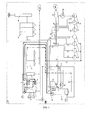
- reference numeral 1 denotes a plant for use of SF for the production of hot gases and steam according to the present invention, linked to a conventional thermoelectric power plant denoted by reference numeral 100.
- the power plant 100 consists of a boiler 101, a Ljungstrom heat exchanger 102, a steam turbine 103 consisting of three coaxial stages (120, 121, 122), connected to a generator of electrical energy 104, two series of low-pressure 105 and high-pressure 106 preheaters, and an electric filter 107 for removing dust from the gases before sending to the stack 108.
- the boiler 101 is of the type with diaphragm walls and cylindrical drum 124, for collecting the recycled condensates Z preheated in the preheaters 105, 106 and in the economiser 110.
- the boiler produces saturated steam which, from the cylindrical drum 124, is sent to the superheaters 111 for the production of high-pressure steam A.
- the fumes leaving the boiler at approximately 375°C and containing approximately 2.5-3.5% oxygen are cooled in the Ljungstrom 102 at temperatures of around 120 - 140°C before sending to the electrostatic filters 107 and subsequent emission at the stack 108.
- Part of these hot fumes are recycled to the boiler and part of these recycled fumes are fed, together with the hot air, to the burner, with the aim of reducing the flame temperature and controlling the formation of NOx.
- the high-pressure superheated steam A leaving the superheater 111 is sent to the high-pressure turbine 120 and the resuperheated steam E leaving the resuperheater 112 is sent to the medium-pressure turbine 121.
- the steam outlet of the medium-pressure turbine is used in the low-pressure turbine 122 and the outlet of the latter goes to the condenser 130 operating at temperatures even close to 15°C in the winter months.
- Steam bleedings X and R are performed on the high-pressure turbine 120, bleedings D and I on the medium-pressure turbine 121 and bleedings M, Y and N on the low-pressure turbine 122.
- the power plant can operate at full load producing 320 MW and at low loads with a technical minimum of 70 MW according to grid demands at seasonal, weekly and day/night rates.
- the plant 1 for use of secondary fuel for the production of electrical energy according to the present invention combined with the thermoelectric power plant 100, comprises a combustor 1' with mechanical stoker or fluidised bed or recirculating bed and equipped with a boiler for the production of saturated steam and an exchanger 2, consisting of a system of superheaters 21 and an economiser 22 for cooling the flue gases and preheating the condensates obtained from the plant preheating, and a purification system comprising neutralisation 3 and dust removal 4 of the fumes before sending them to the thermoelectric power plant 100.
- the combustor 1' is for example of the boiling fluidised bed or recirculating bed type, operating with sand, magnesium carbonate and dolomite at temperatures between 800°C and 900°C, preferably close to 850°C.
- the fumes leaving the economiser 2 have a temperature between 150 and 500°C, preferably between 200 and 400°C and in any case such as to allow subsequent purification.
- the excess of comburent air in relation to the stoichiometric value is between the stoichiometric value and 200% and preferably such as to guarantee a concentration of oxygen in the fumes around 6% in volume.
- the hot gases from heat recovery 2 are neutralised in a post-treatment chamber 3 with soda in solution or with steam soda or with basic carbonates or oxides to remove the sulphur and chlorine not held in the fluidised bed by the neutralising agents present.
- Dust removal 4 is performed with bag filters or by means of electrostatic filters at temperatures between 150°C and 500°C and preferably between 200 and 400°C.
- Any traces of micropollutants present can be eliminated or reduced during subsequent combustion in the boiler of the electrical power plant and cannot form again, the possible precursors having been separated during neutralisation 3 and filtering 4.
- cold false air can be fed in order to regulate the temperature and enrich the oxygen.
- the neutralised and filtered gas is sent onto the recycled fumes of the boiler and can be in such a quantity as to replace them completely.
- the slightly superheated or saturated steam leaving the superheater 21 is sent directly into the cylindrical body 124 of the boiler 101 of the electrical power plant wherefrom it is distributed to the superheaters 111 which produce the high pressure steam to be fed to the high pressure turbine 120.
- the condensates are recycled to said SF combustor, taking them for example after preheating at low pressure 105 at a temperature of approximately 170°C.
- the combustor 1' produces 200 t/h of hot fumes at 400°C which are neutralised with soda in solution in a tower 3 with complete evaporation of the solution, and filtered in a bag filter 4 with temperature-resistant screens.
- the fumes are fed on the recycled fumes of the boiler 101 of the power plant and replace all or part of said recycled fumes, performing the same function as the same recycled fumes.
- the combustor 1' produces 119 t/h saturated steam at 355°C and 173 atmospheres, suitable for being fed into the cylindrical body 124 of the boiler 101 of the power plant.
Landscapes
- Engineering & Computer Science (AREA)
- Mechanical Engineering (AREA)
- General Engineering & Computer Science (AREA)
- Chemical & Material Sciences (AREA)
- Combustion & Propulsion (AREA)
- Engine Equipment That Uses Special Cycles (AREA)
- Physical Or Chemical Processes And Apparatus (AREA)
- Fertilizers (AREA)
Applications Claiming Priority (2)
| Application Number | Priority Date | Filing Date | Title |
|---|---|---|---|
| ITMI20022725 | 2002-12-20 | ||
| IT002725A ITMI20022725A1 (it) | 2002-12-20 | 2002-12-20 | Metodo ed impianto per l'utilizzo di rifiuti in una |
Publications (3)
| Publication Number | Publication Date |
|---|---|
| EP1430952A2 true EP1430952A2 (de) | 2004-06-23 |
| EP1430952A3 EP1430952A3 (de) | 2006-04-26 |
| EP1430952B1 EP1430952B1 (de) | 2011-03-23 |
Family
ID=32375557
Family Applications (1)
| Application Number | Title | Priority Date | Filing Date |
|---|---|---|---|
| EP03028497A Expired - Lifetime EP1430952B1 (de) | 2002-12-20 | 2003-12-12 | Verfahren und Anlage zur Verwendung von Abfall in einem elektrischen Kraftwerk |
Country Status (4)
| Country | Link |
|---|---|
| EP (1) | EP1430952B1 (de) |
| AT (1) | ATE503153T1 (de) |
| DE (1) | DE60336448D1 (de) |
| IT (1) | ITMI20022725A1 (de) |
Cited By (1)
| Publication number | Priority date | Publication date | Assignee | Title |
|---|---|---|---|---|
| EP2265802A4 (de) * | 2008-02-28 | 2014-03-19 | Roger Ferguson | Hybridkraftwerk |
Family Cites Families (3)
| Publication number | Priority date | Publication date | Assignee | Title |
|---|---|---|---|---|
| US3884193A (en) * | 1974-03-22 | 1975-05-20 | Foster Wheeler Corp | Vapor generating system and method |
| ATA121889A (de) * | 1989-05-22 | 1995-02-15 | Sonnek Rudolf Ing | Verfahren zur verwendung von müll als brennstoff für umweltfreundliche stromerzeugung |
| JPH1047638A (ja) * | 1996-08-05 | 1998-02-20 | Hitachi Ltd | 排ガス処理方法および装置ならびにごみ焼却発電プラント |
-
2002
- 2002-12-20 IT IT002725A patent/ITMI20022725A1/it unknown
-
2003
- 2003-12-12 AT AT03028497T patent/ATE503153T1/de not_active IP Right Cessation
- 2003-12-12 EP EP03028497A patent/EP1430952B1/de not_active Expired - Lifetime
- 2003-12-12 DE DE60336448T patent/DE60336448D1/de not_active Expired - Lifetime
Cited By (1)
| Publication number | Priority date | Publication date | Assignee | Title |
|---|---|---|---|---|
| EP2265802A4 (de) * | 2008-02-28 | 2014-03-19 | Roger Ferguson | Hybridkraftwerk |
Also Published As
| Publication number | Publication date |
|---|---|
| EP1430952B1 (de) | 2011-03-23 |
| ITMI20022725A1 (it) | 2004-06-21 |
| EP1430952A3 (de) | 2006-04-26 |
| ATE503153T1 (de) | 2011-04-15 |
| DE60336448D1 (de) | 2011-05-05 |
Similar Documents
| Publication | Publication Date | Title |
|---|---|---|
| JP5592025B2 (ja) | 再熱サイクルを具備するハイブリッドバイオマスプロセス | |
| Li et al. | A novel waste-to-energy system based on sludge hydrothermal treatment and medical waste plasma gasification and integrated with the waste heat recovery of a cement plant | |
| Korobitsyn et al. | Possibilities for gas turbine and waste incinerator integration | |
| CN210568440U (zh) | 一种可提高热效率的垃圾焚烧发电系统 | |
| US7966977B2 (en) | Method and device for the production of superheated steam | |
| CN103343955A (zh) | 钢厂富余煤气与饱和蒸汽综合回收利用锅炉装置 | |
| WO2016193759A1 (en) | Turbine system and method | |
| Wang et al. | Thermo-economic analysis of a waste-to-energy assisted carbon capture system for a coal-fired power plant | |
| US4503681A (en) | State-of-the-art gas turbine and steam turbine power plant | |
| CN113072967A (zh) | 一种燃煤耦合生物质热解的多联产工艺 | |
| EP1172525A1 (de) | Methode zum Umbau von Kessel-Turbinen-Kraftanlagen und umgebaute Kessel-Turbinen-Kraftanlagen | |
| CN108868907A (zh) | 一种燃煤生物质汽水耦合发电系统及工艺 | |
| CN112503497A (zh) | 基于轻型燃机与生物质直燃炉排型锅炉耦合的联合循环热力系统 | |
| JPH09317407A (ja) | 重質油焚き複合発電設備 | |
| JP2006009574A (ja) | 火力発電プラント | |
| EP1430952B1 (de) | Verfahren und Anlage zur Verwendung von Abfall in einem elektrischen Kraftwerk | |
| EP1428987B1 (de) | Methode und Vorrichtung zur Verbesserung des Verbrauchs von fossilen Brennstoffen in konventionellen elektrischen Kraftwerken | |
| JPH06221110A (ja) | 廃棄物または特殊廃棄物の燃焼プラントにおけるエネルギー製造方法 | |
| JP2008101474A (ja) | 木質バイオマス焚きマイクロガスタービン発電装置とその運転制御方法 | |
| CN209976638U (zh) | 一种用于垃圾焚烧与燃气轮机联合发电的系统 | |
| CN119267878A (zh) | 供热系统及方法 | |
| CN218154255U (zh) | 垃圾焚烧处置电站自平衡再热系统 | |
| CN111473314B (zh) | 一种超高压一次再热发电系统 | |
| CN114961901A (zh) | 以二氧化碳为循环工质的生物质直燃cfb锅炉发电系统 | |
| EP1416223B1 (de) | Verfahren und Anlage zur umweltfreundlichen Energienutzung von Abfällen in Verbindung mit einem Kombikraftwerk |
Legal Events
| Date | Code | Title | Description |
|---|---|---|---|
| PUAI | Public reference made under article 153(3) epc to a published international application that has entered the european phase |
Free format text: ORIGINAL CODE: 0009012 |
|
| AK | Designated contracting states |
Kind code of ref document: A2 Designated state(s): AT BE BG CH CY CZ DE DK EE ES FI FR GB GR HU IE IT LI LU MC NL PT RO SE SI SK TR |
|
| AX | Request for extension of the european patent |
Extension state: AL LT LV MK |
|
| PUAL | Search report despatched |
Free format text: ORIGINAL CODE: 0009013 |
|
| AK | Designated contracting states |
Kind code of ref document: A3 Designated state(s): AT BE BG CH CY CZ DE DK EE ES FI FR GB GR HU IE IT LI LU MC NL PT RO SE SI SK TR |
|
| AX | Request for extension of the european patent |
Extension state: AL LT LV MK |
|
| RIC1 | Information provided on ipc code assigned before grant |
Ipc: F01K 3/24 20060101ALI20060306BHEP Ipc: B03B 9/06 20060101ALI20060306BHEP Ipc: F23G 5/02 20060101AFI20060306BHEP |
|
| 17P | Request for examination filed |
Effective date: 20061011 |
|
| AKX | Designation fees paid |
Designated state(s): AT BE BG CH CY CZ DE DK EE ES FI FR GB GR HU IE IT LI LU MC NL PT RO SE SI SK TR |
|
| AXX | Extension fees paid |
Extension state: LV Payment date: 20061011 Extension state: AL Payment date: 20061011 Extension state: MK Payment date: 20061011 Extension state: LT Payment date: 20061011 |
|
| GRAP | Despatch of communication of intention to grant a patent |
Free format text: ORIGINAL CODE: EPIDOSNIGR1 |
|
| GRAS | Grant fee paid |
Free format text: ORIGINAL CODE: EPIDOSNIGR3 |
|
| GRAA | (expected) grant |
Free format text: ORIGINAL CODE: 0009210 |
|
| AK | Designated contracting states |
Kind code of ref document: B1 Designated state(s): AT BE BG CH CY CZ DE DK EE ES FI FR GB GR HU IE IT LI LU MC NL PT RO SE SI SK TR |
|
| AX | Request for extension of the european patent |
Extension state: AL LT LV MK |
|
| REG | Reference to a national code |
Ref country code: GB Ref legal event code: FG4D |
|
| REG | Reference to a national code |
Ref country code: CH Ref legal event code: EP |
|
| RAP2 | Party data changed (patent owner data changed or rights of a patent transferred) |
Owner name: ECODECO S.R.L. |
|
| REG | Reference to a national code |
Ref country code: IE Ref legal event code: FG4D |
|
| REF | Corresponds to: |
Ref document number: 60336448 Country of ref document: DE Date of ref document: 20110505 Kind code of ref document: P |
|
| REG | Reference to a national code |
Ref country code: DE Ref legal event code: R096 Ref document number: 60336448 Country of ref document: DE Effective date: 20110505 |
|
| REG | Reference to a national code |
Ref country code: NL Ref legal event code: VDEP Effective date: 20110323 |
|
| PG25 | Lapsed in a contracting state [announced via postgrant information from national office to epo] |
Ref country code: GR Free format text: LAPSE BECAUSE OF FAILURE TO SUBMIT A TRANSLATION OF THE DESCRIPTION OR TO PAY THE FEE WITHIN THE PRESCRIBED TIME-LIMIT Effective date: 20110624 Ref country code: SE Free format text: LAPSE BECAUSE OF FAILURE TO SUBMIT A TRANSLATION OF THE DESCRIPTION OR TO PAY THE FEE WITHIN THE PRESCRIBED TIME-LIMIT Effective date: 20110323 |
|
| LTIE | Lt: invalidation of european patent or patent extension |
Effective date: 20110323 |
|
| PG25 | Lapsed in a contracting state [announced via postgrant information from national office to epo] |
Ref country code: SI Free format text: LAPSE BECAUSE OF FAILURE TO SUBMIT A TRANSLATION OF THE DESCRIPTION OR TO PAY THE FEE WITHIN THE PRESCRIBED TIME-LIMIT Effective date: 20110323 Ref country code: AT Free format text: LAPSE BECAUSE OF FAILURE TO SUBMIT A TRANSLATION OF THE DESCRIPTION OR TO PAY THE FEE WITHIN THE PRESCRIBED TIME-LIMIT Effective date: 20110323 Ref country code: FI Free format text: LAPSE BECAUSE OF FAILURE TO SUBMIT A TRANSLATION OF THE DESCRIPTION OR TO PAY THE FEE WITHIN THE PRESCRIBED TIME-LIMIT Effective date: 20110323 Ref country code: BG Free format text: LAPSE BECAUSE OF FAILURE TO SUBMIT A TRANSLATION OF THE DESCRIPTION OR TO PAY THE FEE WITHIN THE PRESCRIBED TIME-LIMIT Effective date: 20110623 Ref country code: CY Free format text: LAPSE BECAUSE OF FAILURE TO SUBMIT A TRANSLATION OF THE DESCRIPTION OR TO PAY THE FEE WITHIN THE PRESCRIBED TIME-LIMIT Effective date: 20110323 |
|
| PG25 | Lapsed in a contracting state [announced via postgrant information from national office to epo] |
Ref country code: BE Free format text: LAPSE BECAUSE OF FAILURE TO SUBMIT A TRANSLATION OF THE DESCRIPTION OR TO PAY THE FEE WITHIN THE PRESCRIBED TIME-LIMIT Effective date: 20110323 |
|
| PG25 | Lapsed in a contracting state [announced via postgrant information from national office to epo] |
Ref country code: PT Free format text: LAPSE BECAUSE OF FAILURE TO SUBMIT A TRANSLATION OF THE DESCRIPTION OR TO PAY THE FEE WITHIN THE PRESCRIBED TIME-LIMIT Effective date: 20110725 Ref country code: EE Free format text: LAPSE BECAUSE OF FAILURE TO SUBMIT A TRANSLATION OF THE DESCRIPTION OR TO PAY THE FEE WITHIN THE PRESCRIBED TIME-LIMIT Effective date: 20110323 |
|
| PG25 | Lapsed in a contracting state [announced via postgrant information from national office to epo] |
Ref country code: SK Free format text: LAPSE BECAUSE OF FAILURE TO SUBMIT A TRANSLATION OF THE DESCRIPTION OR TO PAY THE FEE WITHIN THE PRESCRIBED TIME-LIMIT Effective date: 20110323 Ref country code: CZ Free format text: LAPSE BECAUSE OF FAILURE TO SUBMIT A TRANSLATION OF THE DESCRIPTION OR TO PAY THE FEE WITHIN THE PRESCRIBED TIME-LIMIT Effective date: 20110323 Ref country code: ES Free format text: LAPSE BECAUSE OF FAILURE TO SUBMIT A TRANSLATION OF THE DESCRIPTION OR TO PAY THE FEE WITHIN THE PRESCRIBED TIME-LIMIT Effective date: 20110704 Ref country code: RO Free format text: LAPSE BECAUSE OF FAILURE TO SUBMIT A TRANSLATION OF THE DESCRIPTION OR TO PAY THE FEE WITHIN THE PRESCRIBED TIME-LIMIT Effective date: 20110323 |
|
| PG25 | Lapsed in a contracting state [announced via postgrant information from national office to epo] |
Ref country code: NL Free format text: LAPSE BECAUSE OF FAILURE TO SUBMIT A TRANSLATION OF THE DESCRIPTION OR TO PAY THE FEE WITHIN THE PRESCRIBED TIME-LIMIT Effective date: 20110323 |
|
| PLBE | No opposition filed within time limit |
Free format text: ORIGINAL CODE: 0009261 |
|
| STAA | Information on the status of an ep patent application or granted ep patent |
Free format text: STATUS: NO OPPOSITION FILED WITHIN TIME LIMIT |
|
| 26N | No opposition filed |
Effective date: 20111227 |
|
| PG25 | Lapsed in a contracting state [announced via postgrant information from national office to epo] |
Ref country code: DK Free format text: LAPSE BECAUSE OF FAILURE TO SUBMIT A TRANSLATION OF THE DESCRIPTION OR TO PAY THE FEE WITHIN THE PRESCRIBED TIME-LIMIT Effective date: 20110323 |
|
| REG | Reference to a national code |
Ref country code: DE Ref legal event code: R097 Ref document number: 60336448 Country of ref document: DE Effective date: 20111227 |
|
| PG25 | Lapsed in a contracting state [announced via postgrant information from national office to epo] |
Ref country code: MC Free format text: LAPSE BECAUSE OF NON-PAYMENT OF DUE FEES Effective date: 20111231 |
|
| REG | Reference to a national code |
Ref country code: CH Ref legal event code: PL |
|
| GBPC | Gb: european patent ceased through non-payment of renewal fee |
Effective date: 20111212 |
|
| REG | Reference to a national code |
Ref country code: FR Ref legal event code: ST Effective date: 20120831 |
|
| REG | Reference to a national code |
Ref country code: IE Ref legal event code: MM4A |
|
| REG | Reference to a national code |
Ref country code: DE Ref legal event code: R119 Ref document number: 60336448 Country of ref document: DE Effective date: 20120703 |
|
| PG25 | Lapsed in a contracting state [announced via postgrant information from national office to epo] |
Ref country code: CH Free format text: LAPSE BECAUSE OF NON-PAYMENT OF DUE FEES Effective date: 20111231 Ref country code: DE Free format text: LAPSE BECAUSE OF NON-PAYMENT OF DUE FEES Effective date: 20120703 Ref country code: GB Free format text: LAPSE BECAUSE OF NON-PAYMENT OF DUE FEES Effective date: 20111212 Ref country code: IE Free format text: LAPSE BECAUSE OF NON-PAYMENT OF DUE FEES Effective date: 20111212 Ref country code: LI Free format text: LAPSE BECAUSE OF NON-PAYMENT OF DUE FEES Effective date: 20111231 |
|
| PG25 | Lapsed in a contracting state [announced via postgrant information from national office to epo] |
Ref country code: FR Free format text: LAPSE BECAUSE OF NON-PAYMENT OF DUE FEES Effective date: 20120102 |
|
| PG25 | Lapsed in a contracting state [announced via postgrant information from national office to epo] |
Ref country code: LU Free format text: LAPSE BECAUSE OF NON-PAYMENT OF DUE FEES Effective date: 20111212 |
|
| PG25 | Lapsed in a contracting state [announced via postgrant information from national office to epo] |
Ref country code: TR Free format text: LAPSE BECAUSE OF FAILURE TO SUBMIT A TRANSLATION OF THE DESCRIPTION OR TO PAY THE FEE WITHIN THE PRESCRIBED TIME-LIMIT Effective date: 20110323 |
|
| PG25 | Lapsed in a contracting state [announced via postgrant information from national office to epo] |
Ref country code: HU Free format text: LAPSE BECAUSE OF FAILURE TO SUBMIT A TRANSLATION OF THE DESCRIPTION OR TO PAY THE FEE WITHIN THE PRESCRIBED TIME-LIMIT Effective date: 20110323 |
|
| PGFP | Annual fee paid to national office [announced via postgrant information from national office to epo] |
Ref country code: IT Payment date: 20221202 Year of fee payment: 20 |
|
| P01 | Opt-out of the competence of the unified patent court (upc) registered |
Effective date: 20230519 |