EP1431003A1 - Mandrin de serrage actionné mécaniquement et clef pour le dégagement des mors - Google Patents
Mandrin de serrage actionné mécaniquement et clef pour le dégagement des mors Download PDFInfo
- Publication number
- EP1431003A1 EP1431003A1 EP03029401A EP03029401A EP1431003A1 EP 1431003 A1 EP1431003 A1 EP 1431003A1 EP 03029401 A EP03029401 A EP 03029401A EP 03029401 A EP03029401 A EP 03029401A EP 1431003 A1 EP1431003 A1 EP 1431003A1
- Authority
- EP
- European Patent Office
- Prior art keywords
- release
- bolt
- chuck
- key
- release key
- Prior art date
- Legal status (The legal status is an assumption and is not a legal conclusion. Google has not performed a legal analysis and makes no representation as to the accuracy of the status listed.)
- Withdrawn
Links
Images


Classifications
-
- B—PERFORMING OPERATIONS; TRANSPORTING
- B23—MACHINE TOOLS; METAL-WORKING NOT OTHERWISE PROVIDED FOR
- B23B—TURNING; BORING
- B23B31/00—Chucks; Expansion mandrels; Adaptations thereof for remote control
- B23B31/02—Chucks
- B23B31/10—Chucks characterised by the retaining or gripping devices or their immediate operating means
- B23B31/12—Chucks with simultaneously-acting jaws, whether or not also individually adjustable
- B23B31/16—Chucks with simultaneously-acting jaws, whether or not also individually adjustable moving radially
- B23B31/16045—Jaws movement actuated by screws and nuts or oblique racks
-
- B—PERFORMING OPERATIONS; TRANSPORTING
- B23—MACHINE TOOLS; METAL-WORKING NOT OTHERWISE PROVIDED FOR
- B23B—TURNING; BORING
- B23B31/00—Chucks; Expansion mandrels; Adaptations thereof for remote control
- B23B31/02—Chucks
- B23B31/10—Chucks characterised by the retaining or gripping devices or their immediate operating means
- B23B31/12—Chucks with simultaneously-acting jaws, whether or not also individually adjustable
- B23B31/16—Chucks with simultaneously-acting jaws, whether or not also individually adjustable moving radially
- B23B31/16295—Chucks with simultaneously-acting jaws, whether or not also individually adjustable moving radially with means preventing the ejection of the jaws
-
- B—PERFORMING OPERATIONS; TRANSPORTING
- B23—MACHINE TOOLS; METAL-WORKING NOT OTHERWISE PROVIDED FOR
- B23Q—DETAILS, COMPONENTS, OR ACCESSORIES FOR MACHINE TOOLS, e.g. ARRANGEMENTS FOR COPYING OR CONTROLLING; MACHINE TOOLS IN GENERAL CHARACTERISED BY THE CONSTRUCTION OF PARTICULAR DETAILS OR COMPONENTS; COMBINATIONS OR ASSOCIATIONS OF METAL-WORKING MACHINES, NOT DIRECTED TO A PARTICULAR RESULT
- B23Q5/00—Driving or feeding mechanisms; Control arrangements therefor
- B23Q5/54—Arrangements or details not restricted to group B23Q5/02 or group B23Q5/22 respectively, e.g. control handles
- B23Q5/58—Safety devices
- B23Q5/585—Preventing the misuse of accessories, e.g. chuck keys
-
- B—PERFORMING OPERATIONS; TRANSPORTING
- B25—HAND TOOLS; PORTABLE POWER-DRIVEN TOOLS; MANIPULATORS
- B25B—TOOLS OR BENCH DEVICES NOT OTHERWISE PROVIDED FOR, FOR FASTENING, CONNECTING, DISENGAGING, OR HOLDING
- B25B33/00—Hand tools not covered by any other group in this subclass
- B25B33/005—Chuck keys
-
- B—PERFORMING OPERATIONS; TRANSPORTING
- B23—MACHINE TOOLS; METAL-WORKING NOT OTHERWISE PROVIDED FOR
- B23B—TURNING; BORING
- B23B2222/00—Materials of tools or workpieces composed of metals, alloys or metal matrices
- B23B2222/12—Brass
Definitions
- the present invention relates to a power chuck for machine tools, especially for lathes, with a chuck body and several jaws, which in radial jaw guides of the chuck body movably arranged and together by a drive radially to the chuck axis are adjustable, with the drive wedge bars belong to the adjustment of the jaws in the chuck body are slidably guided transversely to the chuck axis and each have a toothing in their working position with a corresponding counter toothing an associated jaw is engaged, with a Adjusting mechanism is provided, one in the chuck body pivot pin and one with the Release pin has detachable release key to by turning the release bolt the wedge rod or a coupling attachment having the toothing the wedge bar parallel to the chuck axis between the working position and a jaw change position in which the Teeth and the counter teeth are disengaged, to move so that the jaws radially out of the chuck body are removable, the release key a Has shaft, at one axial end a coupling element for connection with the release bolt
- Chucks for machine tools of this type are known and are used primarily on lathes in practice used to clamp the workpieces to be machined.
- the conventional chucks consist of one dimensionally stable chuck body, which has a central receiving opening for the workpieces, as well as from several Clamping jaws that are radial in the jaw guides of the chuck body are movable.
- manually operated manual chucks are used in more complex machine tools, in particular in program-controlled automatic lathes, often so-called Power chucks used in which the the clamping jaws exerted on the workpiece be generated by motor or hydraulically.
- DE-A-43 35 896 is a power chuck known that the principle of moving in a straight line Wedge bars that works across the guide grooves wedge bar pockets provided for the clamping jaws are movably guided.
- the wedge bars which by a cylinder arranged in the chuck body driven are with the jaws over helical gears coupled such that the tangential movements of the Wedge bars in the wedge bar pockets in radial clamping movements the jaws are implemented.
- each wedge bar can be used an eccentric actuator (eccentric bolt), which in the wedge bar engages and by means of a release key can be rotated from the outside, adjusted axially, so that their teeth are disengaged from the counter teeth the associated jaw comes and the Clamping jaw radially from the guide groove in the chuck body can be pulled out.
- eccentric actuator eccentric bolt
- the wedge rods are axially displaceable in a radially displaceable to the chuck axis Drift jaw held.
- this chuck is the Driving jaw via a wedge hook coupling by means of a axially movable chuck piston radially adjustable to move the jaw together with the wedge bar, and can face the wedge bar parallel to the chuck axis
- the jaws are moved to disengage them bring from the jaw, so that the jaw from the guide groove in the chuck body can.
- the object of the invention is therefore a power chuck of the type mentioned and a release key to specify the risk of accidents to reduce.
- the Shank of the release key is surrounded by a sleeve is that between a starting position in which it is Coupling element essentially surrounds so that it is a coupling connection between the release key and prevents the release bolt, and a release position, in which it releases the coupling element, so that a connection between the release key and the Notching bolt is possible axially opposite the shaft is adjustable, a compression spring being provided, which pushes the sleeve into the starting position.
- the invention is therefore based on the consideration Training release key in such a way that he himself automatically detaches from the chuck body when it is removed from the Operator is released. For this is on the Shaft provided a sleeve, which in its initial position surrounds the coupling element. If now the coupling element into the corresponding key surface of the release bolt is inserted, the sleeve comes on the front in contact with the release bolt. This will create a further axial movement of the sleeve is prevented with the Consequence that the shaft with the coupling element counter the restoring force of the compression spring relative to the sleeve is moved further into the release bolt and this is rotated can be.
- a locking device which a connection between the release key and the The release bolt is locked and the release key is released of the release pin only if the release pin in one of the working positions of the wedge bar corresponding rotational position.
- the notching device one in one Cross hole of the release bolt arranged locking element in particular in the form of a ball that in the position corresponding to the working position of the wedge bar Rotational position of the release bolt in a recess in the chuck body can dodge radially outwards and in it deviating rotational positions of the release bolt on such Evasion prevented outwards and radially inwards in the interior of the key surface of the release bolt is pressed to with a recess of the release key to come into engagement and so to them lock.
- Such a locking of the release key is basically already known on the chuck body.
- the sleeve is made preferably from a metal such as Brass.
- a metal such as Brass.
- other materials can be used in the same Be used wisely.
- the compression spring is provided in a housing which surrounds the shaft.
- the sleeve preferably protrudes also into the housing, with stop surfaces on the housing and the sleeve the axial Limit adjustment of the sleeve and in this way the Can define starting position.
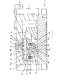
- FIG. 1 to 5 is an embodiment of a Chuck according to the present invention, for example for clamping workpieces Lathes can be used.
- a chuck body 1 cylindrical basic shape, the its rear end face on the not shown A machine tool spindle can be attached.
- the chuck body has a central passage 2, in a workpiece to be clamped can be used.
- the chuck shown is conventional. wise designed as a three-jaw chuck. Accordingly are on the front face of the chuck body 1 three radial Jaw guides 3 are provided, which are even over the Scope distributed, i.e. offset from each other by 120 ° are arranged.
- Clamping jaws 4 used, each from a base jaw and a screw-on top jaw can. Only the base jaw is shown in the drawing the jaws 4 shown.
- the three jaws 4 can be tensioned by a wedge bar mechanism Loosening of workpieces jointly adjusted inwards and outwards become.
- This wedge bar mechanism includes three wedge bars 5, each assigned to one of the jaws 4 and in Chuck body 1 adjustable across the jaw guides 3 are held.
- the wedge bars 5 each an elongated wedge rod body 5a, which in the Chuck body 1 is arranged adjustable and on his a radially inner end with oblique to Chuck axis A extending wedge surfaces 6 is provided, the one with the corresponding wedge surfaces only indicated Feed piston K cooperate to an axial movement of the Chuck piston K in the chuck body 1 in a radial movement to implement the wedge rod body 5a.
- the wedge bars 5 also each have a coupling attachment 5b, the on its front carries a toothing 7, which in a corresponding counter toothing 8 on the associated Clamping jaw 4 engages.
- the wedge bar 5 and the jaw 4 shown in their coupling position. The decoupling position is not shown.
- the coupling attachments 5b is essentially plate-shaped and in a corresponding recess 9 at the top of the respective wedge bar body 5 used.
- the coupling attachment 5b is in a form-fitting connection with the wedge rod body 5a, so that a tilting of the coupling attachment 5b is prevented.
- the coupling attachments 5b are opposite the wedge rod bodies 5a between an upper one Working position and a lower jaw change position movable.
- each coupling attachment 5b has on it Underside a bolt-shaped guide extension 11 on the in a corresponding guide bore 17 of the Wedge rod body 5a engages.
- the coupling attachment 5b on the wedge rod body 5a two compression springs 15 supported, which in the wedge rod body 5a are arranged and the coupling attachment 5b via corresponding pressure pieces 16 against the clamping jaw 4 to press into the working position.
- an actuator in the form of an eccentric bolt 12 provided in a transverse bore 13 of the wedge rod body 5a is rotatably mounted and as Eccentric an extension projecting radially from the bolt 12 in the form of a pin 14.
- This pin 14 engages in a recess 18 of the guide pin 11 of the Wedge bar attachment 5b and comes after a rotation of the eccentric bolt 12 from the position shown in Figure 3 engaged by approximately 80 ° in a counterclockwise direction with a counter surface 19 of the guide pin 11, so that the wedge bar attachment 5b with a further rotation is pressed down until the teeth 7 of the wedge rod 5 completely from the counter toothing 8 of the clamping jaw 4 is retracted and the jaw 4 in radial Direction from the jaw guide 3 in the chuck body 1 can be pulled out (jaw change position).
- the coupling attachment 5b by the two compression springs 15 compared to the Wedge rod body 5a supported and up against the Jaw 4 pressed.
- this has the consequence that the spring force of the compression springs 15 must be overcome, around the coupling attachment 5b by rotating the eccentric bolt 12 to disengage from the jaw 4, on the other hand, the coupling attachment 5b the restoring force of the compression springs 15 again automatically raised while rotating the eccentric bolt 12 when an operator releases the release key 21 releases.
- the arrangement is such that the Compression springs 15 the eccentric 12 not completely in the starting position, but only turn back so far that an overlap, but not a complete intervention the teeth 7, 8 takes place. This ensures that the jaw 4 only then from the jaw guide 3 can be pulled out as long as the operator holds the release key 21, i.e. the Jaw change is definitely desired.
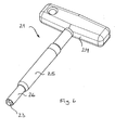
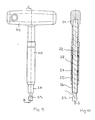
- a release key 21 is shown in FIGS of the present invention.
- This release key includes a shaft 22 which is on its front axial end a coupling element 23 in the form of a Hexagon head for the engagement in the key surfaces of the release pin P and at its rear provided axial end with a grip element 24 is. as can be seen particularly well in FIGS. 8 and 10 leave, the release key 21 still has a Plastic housing 25 which extends from the grip element 24 extending towards the front end and surrounds the shaft 22.
- a sleeve 26 is made Brass on the front end of the release key 21 provided, which with its rear end in the housing 25 engages. The sleeve 26 is opposite the shaft 22 between the initial position shown in FIGS.
- Such an automatic release of the release key 21 of the chuck body 1 takes place in the illustrated embodiment only in the event that the release pin P is in its starting position, which is the working position corresponds to the coupling attachment 5b. Otherwise becomes a release of the release key 21 from the release pin P prevented by a locking device.
- This locking device as known per se and shown in Figure 2 comprises a ball 29, which is arranged in a transverse bore 30 of the release bolt P.
Landscapes
- Engineering & Computer Science (AREA)
- Mechanical Engineering (AREA)
- Gripping On Spindles (AREA)
Priority Applications (1)
| Application Number | Priority Date | Filing Date | Title |
|---|---|---|---|
| DE20320649U DE20320649U1 (de) | 2002-12-21 | 2003-12-19 | Kraftspannfutter und Ausklinkschlüssel dafür |
Applications Claiming Priority (2)
| Application Number | Priority Date | Filing Date | Title |
|---|---|---|---|
| DE10260493 | 2002-12-21 | ||
| DE2002160493 DE10260493A1 (de) | 2002-12-21 | 2002-12-21 | Kraftspannfutter und Ausklinkschlüssel dafür |
Publications (1)
| Publication Number | Publication Date |
|---|---|
| EP1431003A1 true EP1431003A1 (fr) | 2004-06-23 |
Family
ID=32336570
Family Applications (1)
| Application Number | Title | Priority Date | Filing Date |
|---|---|---|---|
| EP03029401A Withdrawn EP1431003A1 (fr) | 2002-12-21 | 2003-12-19 | Mandrin de serrage actionné mécaniquement et clef pour le dégagement des mors |
Country Status (2)
| Country | Link |
|---|---|
| EP (1) | EP1431003A1 (fr) |
| DE (1) | DE10260493A1 (fr) |
Cited By (5)
| Publication number | Priority date | Publication date | Assignee | Title |
|---|---|---|---|---|
| US7516964B2 (en) * | 2002-12-20 | 2009-04-14 | Schunk Gmbh & Co. Kg Spann-Und-Greiftechnik | Clamping chuck and key rod therefor |
| CN110026930A (zh) * | 2019-05-30 | 2019-07-19 | 国网河南省电力公司电力科学研究院 | 一种用于输电杆塔双帽螺栓施工的套筒式扳手 |
| CN111565887A (zh) * | 2018-02-16 | 2020-08-21 | 株式会社北川铁工所 | 卡盘机构以及顶爪 |
| WO2020245000A1 (fr) * | 2019-06-06 | 2020-12-10 | Wto Vermögensverwaltung Gmbh | Clé de service pour porte-outils fixes et entraînés |
| CN117260140A (zh) * | 2023-11-21 | 2023-12-22 | 合肥万向钱潮汽车零部件有限公司 | 一种传动轴摩擦焊快换卡盘 |
Citations (8)
| Publication number | Priority date | Publication date | Assignee | Title |
|---|---|---|---|---|
| US2598119A (en) * | 1949-05-09 | 1952-05-27 | John W Goff | Chuck wrench ejector |
| DE2949566A1 (de) * | 1979-12-10 | 1981-06-11 | SMW Schneider & Weißhaupt GmbH, 7996 Meckenbeuren | Spannfutter fuer drehmaschinen |
| DE3834735A1 (de) * | 1988-10-12 | 1990-04-19 | Smw Spanneinrichtungen | Spannfutter fuer drehmaschinen |
| DE4016775C1 (fr) * | 1990-05-25 | 1991-04-18 | Paul Forkardt Gmbh & Co Kg, 4000 Duesseldorf, De | |
| DE4335896A1 (de) * | 1993-10-21 | 1995-04-27 | Theo Hage Spannwerkzeuge Gmbh | Spannfutter für Drehmaschinen |
| DE19502363C1 (de) * | 1995-01-26 | 1996-01-25 | Smw Autoblok Spannsysteme Gmbh | Spannfutter |
| DE19837147A1 (de) * | 1998-08-17 | 2000-03-02 | Fritz Schunk Gmbh & Co Kg | Spannfutter für Werkzeugmaschinen |
| DE19860747A1 (de) * | 1998-12-23 | 2000-07-06 | Dirk Schiebel | Sicherheitsspannschlüssel, insbesondere für Spannfutter |
-
2002
- 2002-12-21 DE DE2002160493 patent/DE10260493A1/de not_active Ceased
-
2003
- 2003-12-19 EP EP03029401A patent/EP1431003A1/fr not_active Withdrawn
Patent Citations (8)
| Publication number | Priority date | Publication date | Assignee | Title |
|---|---|---|---|---|
| US2598119A (en) * | 1949-05-09 | 1952-05-27 | John W Goff | Chuck wrench ejector |
| DE2949566A1 (de) * | 1979-12-10 | 1981-06-11 | SMW Schneider & Weißhaupt GmbH, 7996 Meckenbeuren | Spannfutter fuer drehmaschinen |
| DE3834735A1 (de) * | 1988-10-12 | 1990-04-19 | Smw Spanneinrichtungen | Spannfutter fuer drehmaschinen |
| DE4016775C1 (fr) * | 1990-05-25 | 1991-04-18 | Paul Forkardt Gmbh & Co Kg, 4000 Duesseldorf, De | |
| DE4335896A1 (de) * | 1993-10-21 | 1995-04-27 | Theo Hage Spannwerkzeuge Gmbh | Spannfutter für Drehmaschinen |
| DE19502363C1 (de) * | 1995-01-26 | 1996-01-25 | Smw Autoblok Spannsysteme Gmbh | Spannfutter |
| DE19837147A1 (de) * | 1998-08-17 | 2000-03-02 | Fritz Schunk Gmbh & Co Kg | Spannfutter für Werkzeugmaschinen |
| DE19860747A1 (de) * | 1998-12-23 | 2000-07-06 | Dirk Schiebel | Sicherheitsspannschlüssel, insbesondere für Spannfutter |
Cited By (11)
| Publication number | Priority date | Publication date | Assignee | Title |
|---|---|---|---|---|
| US7516964B2 (en) * | 2002-12-20 | 2009-04-14 | Schunk Gmbh & Co. Kg Spann-Und-Greiftechnik | Clamping chuck and key rod therefor |
| CN111565887A (zh) * | 2018-02-16 | 2020-08-21 | 株式会社北川铁工所 | 卡盘机构以及顶爪 |
| KR20200120606A (ko) * | 2018-02-16 | 2020-10-21 | 가부시키가이샤 기타가와 뎃꼬쇼 | 척 기구 및 톱 조 |
| JPWO2019159823A1 (ja) * | 2018-02-16 | 2021-01-28 | 株式会社北川鉄工所 | チャック機構及びトップジョー |
| EP3753673A4 (fr) * | 2018-02-16 | 2021-04-14 | Kitagawa Iron Works Co., Ltd | Mécanisme de mandrin et mâchoire supérieure |
| US11389880B2 (en) | 2018-02-16 | 2022-07-19 | Kitagawa Iron Works Co., Ltd | Chuck mechanism and top jaw |
| CN110026930A (zh) * | 2019-05-30 | 2019-07-19 | 国网河南省电力公司电力科学研究院 | 一种用于输电杆塔双帽螺栓施工的套筒式扳手 |
| WO2020245000A1 (fr) * | 2019-06-06 | 2020-12-10 | Wto Vermögensverwaltung Gmbh | Clé de service pour porte-outils fixes et entraînés |
| US12325076B2 (en) | 2019-06-06 | 2025-06-10 | Wto Vermögensverwaltung Gmbh | Operating key for stationary and driven tool holders |
| CN117260140A (zh) * | 2023-11-21 | 2023-12-22 | 合肥万向钱潮汽车零部件有限公司 | 一种传动轴摩擦焊快换卡盘 |
| CN117260140B (zh) * | 2023-11-21 | 2024-02-02 | 合肥万向钱潮汽车零部件有限公司 | 一种传动轴摩擦焊快换卡盘 |
Also Published As
| Publication number | Publication date |
|---|---|
| DE10260493A1 (de) | 2004-07-15 |
Similar Documents
| Publication | Publication Date | Title |
|---|---|---|
| DE69108019T2 (de) | Bohrwerkzeug. | |
| DE69108784T2 (de) | Schlüsselloses Spannfutter. | |
| EP0380974A2 (fr) | Adaptateur pour la fixation d'un outil supplémentaire | |
| EP3191245B1 (fr) | Mandrin de serrage | |
| DE10259959B4 (de) | Kraftspannfutter und Keilstange dafür | |
| EP0450135B1 (fr) | Perceuse pour l'élimination des points de soudage | |
| DE2210668C3 (de) | Gewindeschneidvorrichtung | |
| EP0458170A2 (fr) | Mandrin | |
| DE2831140A1 (de) | Spannzange | |
| DE3437505A1 (de) | Selbstzentrierendes spannfutter mit einstellbaren und austauschbaren spannbacken | |
| EP1431003A1 (fr) | Mandrin de serrage actionné mécaniquement et clef pour le dégagement des mors | |
| DE4214838A1 (de) | Spannfutter | |
| EP2777848B1 (fr) | Dispositif de serrage ou de préhension | |
| WO2002036282A1 (fr) | Adaptateur, procede pour la decoupe de trous polygonaux et procede pour l'application d'ecrous a river aveugles et de boulons rives aveugles par utilisation d'un tel adaptateur | |
| DE19837147C5 (de) | Spannfutter für Werkzeugmaschinen | |
| DE20320649U1 (de) | Kraftspannfutter und Ausklinkschlüssel dafür | |
| EP1862241B1 (fr) | Mandrin de serrage actionné mécaniquement | |
| EP2777850A1 (fr) | Dispositif de serrage ou de préhension | |
| DE29604036U1 (de) | Werkzeughalter für Werkzeugmaschinen | |
| DE10241827B3 (de) | Kraftspannfutter und Keilstange dafür | |
| EP0178417A1 (fr) | Outil divisible pou l'usinage | |
| DE2916179A1 (de) | Spanneinrichtung, insbesondere maschinenschraubstock | |
| DE8506915U1 (de) | Werkzeug zur Herstellung von Bohrungen mit einem von der Kreisform abweichenden Querschnitt | |
| DE108978C (fr) | ||
| DE3436470A1 (de) | Einstechwerkzeug |
Legal Events
| Date | Code | Title | Description |
|---|---|---|---|
| PUAI | Public reference made under article 153(3) epc to a published international application that has entered the european phase |
Free format text: ORIGINAL CODE: 0009012 |
|
| AK | Designated contracting states |
Kind code of ref document: A1 Designated state(s): AT BE BG CH CY CZ DE DK EE ES FI FR GB GR HU IE IT LI LU MC NL PT RO SE SI SK TR |
|
| AX | Request for extension of the european patent |
Extension state: AL LT LV MK |
|
| RAP1 | Party data changed (applicant data changed or rights of an application transferred) |
Owner name: SCHUNK GMBH & CO. KG SPANN- UND GREIFTECHNIK |
|
| AKX | Designation fees paid | ||
| REG | Reference to a national code |
Ref country code: DE Ref legal event code: 8566 |
|
| STAA | Information on the status of an ep patent application or granted ep patent |
Free format text: STATUS: THE APPLICATION IS DEEMED TO BE WITHDRAWN |
|
| 18D | Application deemed to be withdrawn |
Effective date: 20041224 |