EP1431012A2 - Organe d'assemblage d'outils plans - Google Patents
Organe d'assemblage d'outils plans Download PDFInfo
- Publication number
- EP1431012A2 EP1431012A2 EP03026318A EP03026318A EP1431012A2 EP 1431012 A2 EP1431012 A2 EP 1431012A2 EP 03026318 A EP03026318 A EP 03026318A EP 03026318 A EP03026318 A EP 03026318A EP 1431012 A2 EP1431012 A2 EP 1431012A2
- Authority
- EP
- European Patent Office
- Prior art keywords
- assembly member
- tools
- fins
- openings
- assembly
- Prior art date
- Legal status (The legal status is an assumption and is not a legal conclusion. Google has not performed a legal analysis and makes no representation as to the accuracy of the status listed.)
- Withdrawn
Links
Images
Classifications
-
- B—PERFORMING OPERATIONS; TRANSPORTING
- B30—PRESSES
- B30B—PRESSES IN GENERAL
- B30B15/00—Details of, or accessories for, presses; Auxiliary measures in connection with pressing
- B30B15/08—Accessory tools, e.g. knives; Mountings therefor
-
- B—PERFORMING OPERATIONS; TRANSPORTING
- B26—HAND CUTTING TOOLS; CUTTING; SEVERING
- B26D—CUTTING; DETAILS COMMON TO MACHINES FOR PERFORATING, PUNCHING, CUTTING-OUT, STAMPING-OUT OR SEVERING
- B26D7/00—Details of apparatus for cutting, cutting-out, stamping-out, punching, perforating, or severing by means other than cutting
- B26D7/18—Means for removing cut-out material or waste
- B26D7/1818—Means for removing cut-out material or waste by pushing out
-
- B—PERFORMING OPERATIONS; TRANSPORTING
- B26—HAND CUTTING TOOLS; CUTTING; SEVERING
- B26D—CUTTING; DETAILS COMMON TO MACHINES FOR PERFORATING, PUNCHING, CUTTING-OUT, STAMPING-OUT OR SEVERING
- B26D7/00—Details of apparatus for cutting, cutting-out, stamping-out, punching, perforating, or severing by means other than cutting
- B26D7/18—Means for removing cut-out material or waste
- B26D2007/189—Mounting blanking, stripping and break-out tools
-
- B—PERFORMING OPERATIONS; TRANSPORTING
- B31—MAKING ARTICLES OF PAPER, CARDBOARD OR MATERIAL WORKED IN A MANNER ANALOGOUS TO PAPER; WORKING PAPER, CARDBOARD OR MATERIAL WORKED IN A MANNER ANALOGOUS TO PAPER
- B31B—MAKING CONTAINERS OF PAPER, CARDBOARD OR MATERIAL WORKED IN A MANNER ANALOGOUS TO PAPER
- B31B50/00—Making rigid or semi-rigid containers, e.g. boxes or cartons
- B31B50/14—Cutting, e.g. perforating, punching, slitting or trimming
- B31B50/20—Cutting sheets or blanks
-
- Y—GENERAL TAGGING OF NEW TECHNOLOGICAL DEVELOPMENTS; GENERAL TAGGING OF CROSS-SECTIONAL TECHNOLOGIES SPANNING OVER SEVERAL SECTIONS OF THE IPC; TECHNICAL SUBJECTS COVERED BY FORMER USPC CROSS-REFERENCE ART COLLECTIONS [XRACs] AND DIGESTS
- Y10—TECHNICAL SUBJECTS COVERED BY FORMER USPC
- Y10T—TECHNICAL SUBJECTS COVERED BY FORMER US CLASSIFICATION
- Y10T403/00—Joints and connections
- Y10T403/70—Interfitted members
- Y10T403/7005—Lugged member, rotary engagement
Definitions
- the present invention relates to a tool assembly member parallel planes, as generally used in pairs in machines production of packaging such as platen presses for example.
- Such machines generally include a series of several treatment stations in which pass, one by one, sheets of paper, cardboard or plastic for obtaining blanks of boxes.
- these sheets are apprehended from above from a pile, then routed to a cutting station where the outlines of each developed box are cut flat between a fixed upper box spring and a movable lower plate on which the sheet rests.
- the latter is then taken to an ejection station where the waste is removed from the rest of the sheet by pinching between a plurality of ejectors. Once cut and cleared of its waste, the sheet is finally taken away in a receiving station to fall on top of an exit stack.
- the corresponding stations are equipped with flat tools, usually formed of a rectangular wooden base plate, in which are in particular inserted knives, respectively ejectors.
- the ejection station generally comprises at least two planar tools, know a perforated lower tool for the downward evacuation of waste from the sheet and a top tool equipped with ejection needles pushing this waste through the openings in the foreground tool.
- the upper tool and the lower tool therefore form a pair of tools plans working together for a series of sheets corresponding to a task specific.
- Storage of these flat tools therefore proves to be rational, in order to be able to later benefit from it during the resumption of identical work.
- the object of the present invention finds its use.
- the latter is made integral of the lower plane tool so that all the eject needles, like a sandwich, are protected between the two constituent boards of two plan tools.
- the assembly thus produced constitutes a rigid assembly that it can easily be stored while waiting for later use.
- each pair of planar tools includes example four circular holes through each of which will come slide a fixing screw.
- the latter crosses a spacer, constituted any piece of tube, previously placed between the two tools plans, in contact with them.
- the length of the spacer is such that it allows to distance said planar tools by a value slightly higher than the length of an ejection needle.
- a nut is finally tightened at the threaded end of the screw, against the outside of one of the plan tools.
- a variant consists in using a washer with a tapped hole. The latter is then previously fixed against either side of the planar tool, concentric to the hole of this tool. From a mechanical point of view, it aims above all to replace a simple tapping impossible to achieve in a sustainable way in planks woods such as those commonly used for flat tools.
- the object of the present invention is to remedy the drawbacks mentioned above by considerably reducing the assembly time of flat tools, minimizing the number of parts required for assembly and lowering the overall cost of such an operation.
- the number of pieces required is reduced to the unit, i.e. one piece by bolting.
- the object of the present invention also provides the advantage to be able to be manipulated and then tightened with one hand, with or without the help of a tightening wrench as required.
- Its fixing mode allows disassembly and separation of planar tools as fast as their assembly. Any substance neither adhesive element nor any other additional mechanical part is therefore necessary for its use.
- the object of the present invention not being not a single-use consumable, it also advantageously limits the number of useful parts in stock. Finally, it can also be carried out in a fully recyclable material while retaining the mechanical qualities required to ensure a solid and reliable assembly.
- the subject of the present invention is an organ assembly according to claim 1.
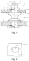
- FIG. 1 represents, in a partial vertical section view, the assembly member 1 connecting an upper planar tool 2 to a lower planar tool 3 parallel to the first, to form a set that can be manipulated as one object.
- This organ consists of a cylindrical body 4 crossing right through the tools planes 2 and 3 and finished in each of its ends by fixing means. These means are preferably constituted by a pair of fins 5 attached against a portion of the circumference of the cylindrical body 4.
- the body cylindrical preferably comprises a middle part 6 ending in two shoulders 7, advantageously flat and parallel, against which support the inner faces 8, 9 respective of the upper planar tools 2 and below 3.
- the cylindrical body 4 is finished at least at one of its ends by a head 10 of conical shape.
- This last has at least one external gripping profile 11 to the assembly member 1, or even a grip profile inside the latter, facilitating its entered either manually or using a tool such as a pipe wrench or fork, for example, so that the member can easily rotate assembly 1 around its axis of rotation 12.
- FIG. 2 shows the shape of the openings 13 no threaded machined in plan tools 2 and 3 in correspondence one and the other in the same vertical plane. These openings can be easily laser machined, in a single operation for example.
- This shape allows, initially, the passage of the upper or lower parts of the assembly member 1 located on either side of the middle part 6 and, secondly, the blocking and tightening of the assembly member 1 through flat tools 2, 3 by a simple rotation, a quarter turn approximately, of the assembly member 1.
- each opening 13 is consists of a central opening 14, of cylindrical shape, and two reported openings 15.
- the two reported openings 15 have shapes of crown portions which are symmetrically arranged against the circumference of the central opening 14.
- the fins 5 are in the form of a ring portion of rectangular section and of regularly variable height between one end and the other of the ring portion.
- each fin with a propeller 25 determining a slightly inclined plane at an angle a with respect to a normal to the axis of rotation 12.
- Each propeller 25 is therefore opposite the nearest planar tool, more precisely the corresponding outer face 18, 19, and allows by revolution around the axis of rotation 12 to gradually tighten this planar tool by forcing it to come to be pressed more and more strongly against the neighboring shoulder 7.
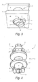
- Figure 3 shows, in an oblique view from below, a perspective of the assembly as shown in Figure 1.
- This figure gives an illustration of the assembly member 1 in a locked position at within plane tools 2 and 3.
- the end lower of the cylindrical body 4 has an internal gripping profile 16 allowing the tip of a hexagon wrench to be inserted, for example.
- this profile internal gripping 16 makes it easier to tighten the assembly member within the plan tools.
- a variant of the present invention could consist of remove the head 10 and replace the external grip profile 11 with a internal gripping profile 16 similar or identical to that illustrated in the figure 3. It would also be perfectly possible to endow the two ends of the head assembly member 10 as described above. It would also be possible to provide a recess inside the body cylindrical 4 so as to further lighten the assembly member 1. At this About, it will also be noted that the middle part 6, as illustrated in the Figure 1, is in the form of a groove thus reducing the mass of the assembly member while preserving mechanical properties perfectly sufficient. However, it is quite clear that the geometry of this middle part is not particular and could perfectly be different.
- the organ of the present invention is preferably provided for the assembly of pairs of parallel planar tools. However, it would also be possible to use it for further assembly. of two planar tools at the same time.
- the assembly member can be easily made of molded plastic. Thanks to the absence of everything threading and the use of propellers 25 lining two pairs of fins symmetrically arranged as in Figure 4, this body has a geometry which very easily allows a molding and demolding process in two parts. However, this preferred embodiment does not however exclude the possibility of providing rather three fins per end, or even a number still different. Finally, it will also be noted that the general shape of the fins, put apart from that of the propeller 25, does not in any way condition the function which is their associated as long as it is possible to pass them without play, even without play excessive, through the openings 13.
Landscapes
- Engineering & Computer Science (AREA)
- Mechanical Engineering (AREA)
- Life Sciences & Earth Sciences (AREA)
- Forests & Forestry (AREA)
- Connection Of Plates (AREA)
- Perforating, Stamping-Out Or Severing By Means Other Than Cutting (AREA)
- Polishing Bodies And Polishing Tools (AREA)
- Insertion Pins And Rivets (AREA)
- Food-Manufacturing Devices (AREA)
- Clamps And Clips (AREA)
- Snaps, Bayonet Connections, Set Pins, And Snap Rings (AREA)
- Details Of Cutting Devices (AREA)
- Forms Removed On Construction Sites Or Auxiliary Members Thereof (AREA)
- Details Of Spanners, Wrenches, And Screw Drivers And Accessories (AREA)
Abstract
Description
dans lesquelles :
- la figure 1 représente, dans une vue en coupe verticale partielle, une partie d'une paire de deux outils plans assemblés à l'aide de l'organe de la présente invention,
- la figure 2 représente, dans une vue en plan, la forme de l'ouverture pratiquée dans les outils plans,
- la figure 3 représente en perspective selon une vue oblique de dessous, l'organe d'assemblage dans une position verrouillée au sein des outils plans,
- la figure 4 représente en perspective l'organe d'assemblage seul, dans une position non verrouillée par rapport à celle qu'il occupe dans la figure 3.
Claims (8)
- Organe d'assemblage (1) d'outils plans (2, 3), à faces intérieures (8, 9) et à faces extérieures (18, 19) toutes parallèles les unes aux autres, au travers desquels sont ménagées par paires, en correspondance dans de mêmes plans verticaux, des ouvertures (13) non taraudées, caractérisé en ce qu'il comprend un corps cylindrique (4), d'axe de rotation (12), contre lequel sont rapportés au moins deux moyens permettant de solidariser et de serrer, sans l'adjonction d'aucune substance ni élément adhésif ni autre pièce mécanique de fixation, lesdits outils plans au travers desdites ouvertures (13) par une rotation, inférieure à 360°, de l'organe d'assemblage (1) autour de son axe de rotation (12).
- Organe d'assemblage (1) selon la revendication 1, caractérisé en ce que lesdits moyens sont constitués par des ailettes (5) comprenant chacune, en vis-à-vis de la face extérieure (18, 19) la plus proche, une hélice (25) contre laquelle l'outil plan (2, 3) correspondant peut être graduellement serré.
- Organe d'assemblage (1) selon la revendication 2, caractérisé en ce que lesdites ailettes (5) s'insèrent sans jeu au travers des ouvertures (13).
- Organe d'assemblage (1) selon la revendication 3, caractérisé en ce que les ailettes (5) sont disposées par paire à chacune des extrémités du corps cylindrique (4).
- Organe d'assemblage (1) selon la revendication 2, caractérisé en ce qu'il comprend une partie médiane (6), située entre au moins deux ailettes opposées, présentant deux épaulements (7) contre lesquels les faces intérieures (8, 9) desdits outils plans (2, 3) prennent appui.
- Organe d'assemblage (1 ) selon la revendication 1, caractérisé en ce qu'il comprend, au moins en l'une de ses extrémités, au moins un profil de préhension (11, 12) facilitant sa révolution autour de son axe de rotation (12).
- Organe d'assemblage (1) selon la revendication 6 caractérisé en ce qu'au moins un des profils de préhension (11, 16) est un profil intérieur à l'organe d'assemblage (1) ou extérieur à ce dernier.
- Organe d'assemblage (1) selon l'une des deux revendications précédentes, caractérisé en ce qu'au moins un profil de préhension (11, 12) est agencé à l'extrémité d'une tête (10) rapportée contre l'une des extrémités dudit organe d'assemblage (1).
Applications Claiming Priority (2)
| Application Number | Priority Date | Filing Date | Title |
|---|---|---|---|
| CH21582002 | 2002-12-18 | ||
| CH21582002 | 2002-12-18 |
Publications (2)
| Publication Number | Publication Date |
|---|---|
| EP1431012A2 true EP1431012A2 (fr) | 2004-06-23 |
| EP1431012A3 EP1431012A3 (fr) | 2005-03-09 |
Family
ID=32331839
Family Applications (1)
| Application Number | Title | Priority Date | Filing Date |
|---|---|---|---|
| EP03026318A Withdrawn EP1431012A3 (fr) | 2002-12-18 | 2003-11-17 | Organe d'assemblage d'outils plans |
Country Status (7)
| Country | Link |
|---|---|
| US (1) | US20040126183A1 (fr) |
| EP (1) | EP1431012A3 (fr) |
| JP (1) | JP2004195645A (fr) |
| KR (1) | KR20040054531A (fr) |
| CN (1) | CN1507979A (fr) |
| BR (1) | BR0306033A (fr) |
| CA (1) | CA2451594A1 (fr) |
Cited By (2)
| Publication number | Priority date | Publication date | Assignee | Title |
|---|---|---|---|---|
| EP2442956A4 (fr) * | 2009-06-17 | 2013-07-10 | Progressive Components Int | Verrou pour ensemble de c ur pour outil de moulage par injection |
| DE202016100980U1 (de) | 2016-02-25 | 2016-06-20 | Cps-Bender Gbr (Vertretungsberechtigter Gesellschafter: Andreas Kurt Bender, 68789 St. Leon-Rot) | Verbindungselement zur Positionierung zweier plattenförmiger Elemente und Stanz- oder Ausbrechwerkzeug |
Families Citing this family (13)
| Publication number | Priority date | Publication date | Assignee | Title |
|---|---|---|---|---|
| US20020144791A1 (en) * | 2001-04-09 | 2002-10-10 | Lawrence Shell | Locking end cap for roller shade |
| CN101223399B (zh) * | 2005-06-09 | 2012-04-18 | 山田明 | 通路块的结合装置 |
| FR2894304A1 (fr) * | 2005-12-05 | 2007-06-08 | Raymond Et Cie Soc En Commandi | Dispositif d'assemblage de deux plaques |
| IL209253A (en) * | 2010-11-11 | 2017-05-29 | Plasan Sasa Ltd | Connection mechanism |
| EP2584108B1 (fr) * | 2011-10-19 | 2015-09-02 | Grundfos Holding A/S | Installation de levage d'eaux usées |
| KR101140326B1 (ko) * | 2012-02-08 | 2012-05-03 | 김영환 | 조립어셈블리 및 이를 이용한 조립용 완구 |
| KR102076117B1 (ko) * | 2012-05-04 | 2020-02-11 | 보르그워너 인코퍼레이티드 | 가변 터빈 구조 베인 팩을 위한 베이오넷 스페이서 유지 시스템 |
| CN106457492B (zh) * | 2014-04-07 | 2020-01-10 | 纽弗雷公司 | 插入工具 |
| CN107218759B (zh) * | 2017-06-30 | 2019-11-05 | 青岛海尔股份有限公司 | 风冷冰箱 |
| DE102017129301A1 (de) * | 2017-12-08 | 2019-06-13 | Khs Gmbh | Verbindungsanordnung |
| CN108222364B (zh) * | 2018-03-27 | 2023-07-14 | 长春工程学院 | 一种组合式复合夹芯保温外墙板 |
| CN108531982A (zh) * | 2018-05-22 | 2018-09-14 | 嘉兴耐进新材料有限公司 | 一种用于多晶硅铸锭坩埚的盖板 |
| JP2023093269A (ja) * | 2021-12-22 | 2023-07-04 | 大和電器株式会社 | 機器における係止部材の固定構造 |
Family Cites Families (3)
| Publication number | Priority date | Publication date | Assignee | Title |
|---|---|---|---|---|
| FR2721074B1 (fr) * | 1994-06-09 | 1996-07-26 | Otis Elevator Co | Verrou pour l'assemblage de panneaux latéraux, d'une plate-forme et d'un plafond de cabine d'ascenseur et procédé d'assemblage. |
| US5875500A (en) * | 1997-06-09 | 1999-03-02 | 2679965 Canada Inc. | Above ground swimming pool |
| US6267543B1 (en) * | 1999-10-13 | 2001-07-31 | Avaya Technology Corp. | Latch with spring |
-
2003
- 2003-11-17 EP EP03026318A patent/EP1431012A3/fr not_active Withdrawn
- 2003-12-01 CA CA002451594A patent/CA2451594A1/fr not_active Abandoned
- 2003-12-15 US US10/737,265 patent/US20040126183A1/en not_active Abandoned
- 2003-12-16 BR BR0306033-0A patent/BR0306033A/pt not_active IP Right Cessation
- 2003-12-17 KR KR1020030092307A patent/KR20040054531A/ko not_active Ceased
- 2003-12-17 JP JP2003418962A patent/JP2004195645A/ja not_active Abandoned
- 2003-12-17 CN CNA2003101212818A patent/CN1507979A/zh active Pending
Cited By (2)
| Publication number | Priority date | Publication date | Assignee | Title |
|---|---|---|---|---|
| EP2442956A4 (fr) * | 2009-06-17 | 2013-07-10 | Progressive Components Int | Verrou pour ensemble de c ur pour outil de moulage par injection |
| DE202016100980U1 (de) | 2016-02-25 | 2016-06-20 | Cps-Bender Gbr (Vertretungsberechtigter Gesellschafter: Andreas Kurt Bender, 68789 St. Leon-Rot) | Verbindungselement zur Positionierung zweier plattenförmiger Elemente und Stanz- oder Ausbrechwerkzeug |
Also Published As
| Publication number | Publication date |
|---|---|
| BR0306033A (pt) | 2004-08-31 |
| KR20040054531A (ko) | 2004-06-25 |
| JP2004195645A (ja) | 2004-07-15 |
| EP1431012A3 (fr) | 2005-03-09 |
| US20040126183A1 (en) | 2004-07-01 |
| CN1507979A (zh) | 2004-06-30 |
| CA2451594A1 (fr) | 2004-06-18 |
Similar Documents
| Publication | Publication Date | Title |
|---|---|---|
| EP1431012A2 (fr) | Organe d'assemblage d'outils plans | |
| EP3179929B1 (fr) | Manche de prehension pour outil chirurgical, procede et machine de fabrication d'un tel manche de prehension | |
| EP2361713B1 (fr) | Dispositif de gestion des électrodes pour machines d'usinage par électroérosion | |
| FR3073386A1 (fr) | Perforateur cranien | |
| FR3070038A1 (fr) | Dispositif de conditionnement d'objet, ensemble et procede d'extraction correspondant | |
| FR2565865A1 (fr) | Mandrin de serrage de pieces, et mors rapporte, ensemble de mors et dispositif de fixation de mors pour ce mandrin | |
| FR2860701A1 (fr) | Dispositif et procede de sectionnement de la lame d'une vertebre | |
| CA2656368A1 (fr) | Support pour une serie d'outils | |
| EP2751349A1 (fr) | Système mécanique comprenant un dispositif de liaison entre une pièce d'usure et son support, godet d'engin de travaux publics et procédé de mise en oeuvre d'un tel système | |
| FR2909574A1 (fr) | Mandrin de serrage. | |
| FR2750744A1 (fr) | Pompe pour fluides alimentaires ou pharmaceutiques a etanchement ameliore | |
| FR2915411A1 (fr) | Peigne a fileter | |
| EP3715029B1 (fr) | Gabarit et procede de percement | |
| EP2752717A1 (fr) | Dispositif de fixation par serrage d'une ébauche de pièce à usiner | |
| FR2938412A1 (fr) | Chassis entoile demontable et son dispositif de liaison et d'ecartement de ses montants creux ou evides | |
| FR3016665A1 (fr) | Element a visser | |
| EP0334226B1 (fr) | Dispositif de fixation d'outils sur un appareil circulaire | |
| EP2770243A2 (fr) | Collier pour bouteille de gaz | |
| FR2910367A1 (fr) | Presse de moulage. | |
| EP3063419B1 (fr) | Bague anti-desserrage d'un ecrou | |
| WO1993008762A1 (fr) | Implant dentaire | |
| BE1024594B1 (fr) | Bandage annulaire monobloc pour diffuseur | |
| FR2967223A1 (fr) | Element de suspension temporaire, et procedes de fixation et de demontage utilisant ledit element | |
| CH692490A5 (fr) | Outil d'éjection des déchets pour une presse à découper des éléments en plaque. | |
| EP2123919A1 (fr) | Assemblage rigide de pièces tubulaires |
Legal Events
| Date | Code | Title | Description |
|---|---|---|---|
| PUAI | Public reference made under article 153(3) epc to a published international application that has entered the european phase |
Free format text: ORIGINAL CODE: 0009012 |
|
| AK | Designated contracting states |
Kind code of ref document: A2 Designated state(s): AT BE BG CH CY CZ DE DK EE ES FI FR GB GR HU IE IT LI LU MC NL PT RO SE SI SK TR |
|
| AX | Request for extension of the european patent |
Extension state: AL LT LV MK |
|
| PUAL | Search report despatched |
Free format text: ORIGINAL CODE: 0009013 |
|
| AK | Designated contracting states |
Kind code of ref document: A3 Designated state(s): AT BE BG CH CY CZ DE DK EE ES FI FR GB GR HU IE IT LI LU MC NL PT RO SE SI SK TR |
|
| AX | Request for extension of the european patent |
Extension state: AL LT LV MK |
|
| STAA | Information on the status of an ep patent application or granted ep patent |
Free format text: STATUS: THE APPLICATION HAS BEEN WITHDRAWN |
|
| 18W | Application withdrawn |
Effective date: 20050613 |