EP1431017A1 - Compacteur avec manchon réglable - Google Patents
Compacteur avec manchon réglable Download PDFInfo
- Publication number
- EP1431017A1 EP1431017A1 EP03028921A EP03028921A EP1431017A1 EP 1431017 A1 EP1431017 A1 EP 1431017A1 EP 03028921 A EP03028921 A EP 03028921A EP 03028921 A EP03028921 A EP 03028921A EP 1431017 A1 EP1431017 A1 EP 1431017A1
- Authority
- EP
- European Patent Office
- Prior art keywords
- sleeve
- component
- shaft
- rotatable
- worm
- Prior art date
- Legal status (The legal status is an assumption and is not a legal conclusion. Google has not performed a legal analysis and makes no representation as to the accuracy of the status listed.)
- Withdrawn
Links
- 239000000463 material Substances 0.000 abstract description 11
- 230000002093 peripheral effect Effects 0.000 abstract description 2
- 239000004033 plastic Substances 0.000 description 12
- 229920003023 plastic Polymers 0.000 description 12
- 238000010276 construction Methods 0.000 description 6
- 239000002699 waste material Substances 0.000 description 5
- 238000005299 abrasion Methods 0.000 description 3
- 238000000034 method Methods 0.000 description 3
- -1 polyethylene Polymers 0.000 description 3
- 239000004952 Polyamide Substances 0.000 description 2
- 239000004743 Polypropylene Substances 0.000 description 2
- 230000008901 benefit Effects 0.000 description 2
- 230000006835 compression Effects 0.000 description 2
- 238000007906 compression Methods 0.000 description 2
- 230000006378 damage Effects 0.000 description 2
- 238000006073 displacement reaction Methods 0.000 description 2
- 238000005516 engineering process Methods 0.000 description 2
- 239000000835 fiber Substances 0.000 description 2
- 239000006260 foam Substances 0.000 description 2
- 229920002647 polyamide Polymers 0.000 description 2
- 229920001155 polypropylene Polymers 0.000 description 2
- 229920001169 thermoplastic Polymers 0.000 description 2
- 239000004698 Polyethylene Substances 0.000 description 1
- 239000004793 Polystyrene Substances 0.000 description 1
- 230000005540 biological transmission Effects 0.000 description 1
- 210000001520 comb Anatomy 0.000 description 1
- 230000000052 comparative effect Effects 0.000 description 1
- 230000000295 complement effect Effects 0.000 description 1
- 238000009434 installation Methods 0.000 description 1
- 238000012423 maintenance Methods 0.000 description 1
- 238000004519 manufacturing process Methods 0.000 description 1
- 239000000155 melt Substances 0.000 description 1
- 239000004745 nonwoven fabric Substances 0.000 description 1
- 229920000728 polyester Polymers 0.000 description 1
- 229920000573 polyethylene Polymers 0.000 description 1
- 229920002223 polystyrene Polymers 0.000 description 1
- 238000004064 recycling Methods 0.000 description 1
- 238000007789 sealing Methods 0.000 description 1
- 239000004416 thermosoftening plastic Substances 0.000 description 1
- 230000007704 transition Effects 0.000 description 1
Images
Classifications
-
- B—PERFORMING OPERATIONS; TRANSPORTING
- B29—WORKING OF PLASTICS; WORKING OF SUBSTANCES IN A PLASTIC STATE IN GENERAL
- B29B—PREPARATION OR PRETREATMENT OF THE MATERIAL TO BE SHAPED; MAKING GRANULES OR PREFORMS; RECOVERY OF PLASTICS OR OTHER CONSTITUENTS OF WASTE MATERIAL CONTAINING PLASTICS
- B29B17/00—Recovery of plastics or other constituents of waste material containing plastics
- B29B17/04—Disintegrating plastics, e.g. by milling
- B29B17/0412—Disintegrating plastics, e.g. by milling to large particles, e.g. beads, granules, flakes, slices
-
- B—PERFORMING OPERATIONS; TRANSPORTING
- B02—CRUSHING, PULVERISING, OR DISINTEGRATING; PREPARATORY TREATMENT OF GRAIN FOR MILLING
- B02C—CRUSHING, PULVERISING, OR DISINTEGRATING IN GENERAL; MILLING GRAIN
- B02C7/00—Crushing or disintegrating by disc mills
- B02C7/02—Crushing or disintegrating by disc mills with coaxial discs
-
- B—PERFORMING OPERATIONS; TRANSPORTING
- B02—CRUSHING, PULVERISING, OR DISINTEGRATING; PREPARATORY TREATMENT OF GRAIN FOR MILLING
- B02C—CRUSHING, PULVERISING, OR DISINTEGRATING IN GENERAL; MILLING GRAIN
- B02C7/00—Crushing or disintegrating by disc mills
- B02C7/11—Details
- B02C7/12—Shape or construction of discs
-
- B—PERFORMING OPERATIONS; TRANSPORTING
- B29—WORKING OF PLASTICS; WORKING OF SUBSTANCES IN A PLASTIC STATE IN GENERAL
- B29B—PREPARATION OR PRETREATMENT OF THE MATERIAL TO BE SHAPED; MAKING GRANULES OR PREFORMS; RECOVERY OF PLASTICS OR OTHER CONSTITUENTS OF WASTE MATERIAL CONTAINING PLASTICS
- B29B17/00—Recovery of plastics or other constituents of waste material containing plastics
- B29B17/0026—Recovery of plastics or other constituents of waste material containing plastics by agglomeration or compacting
-
- B—PERFORMING OPERATIONS; TRANSPORTING
- B30—PRESSES
- B30B—PRESSES IN GENERAL
- B30B9/00—Presses specially adapted for particular purposes
- B30B9/30—Presses specially adapted for particular purposes for baling; Compression boxes therefor
- B30B9/3082—Presses specially adapted for particular purposes for baling; Compression boxes therefor with compression means other than rams performing a rectilinear movement
-
- B—PERFORMING OPERATIONS; TRANSPORTING
- B29—WORKING OF PLASTICS; WORKING OF SUBSTANCES IN A PLASTIC STATE IN GENERAL
- B29B—PREPARATION OR PRETREATMENT OF THE MATERIAL TO BE SHAPED; MAKING GRANULES OR PREFORMS; RECOVERY OF PLASTICS OR OTHER CONSTITUENTS OF WASTE MATERIAL CONTAINING PLASTICS
- B29B17/00—Recovery of plastics or other constituents of waste material containing plastics
- B29B17/04—Disintegrating plastics, e.g. by milling
- B29B2017/0424—Specific disintegrating techniques; devices therefor
- B29B2017/0484—Grinding tools, roller mills or disc mills
-
- Y—GENERAL TAGGING OF NEW TECHNOLOGICAL DEVELOPMENTS; GENERAL TAGGING OF CROSS-SECTIONAL TECHNOLOGIES SPANNING OVER SEVERAL SECTIONS OF THE IPC; TECHNICAL SUBJECTS COVERED BY FORMER USPC CROSS-REFERENCE ART COLLECTIONS [XRACs] AND DIGESTS
- Y02—TECHNOLOGIES OR APPLICATIONS FOR MITIGATION OR ADAPTATION AGAINST CLIMATE CHANGE
- Y02W—CLIMATE CHANGE MITIGATION TECHNOLOGIES RELATED TO WASTEWATER TREATMENT OR WASTE MANAGEMENT
- Y02W30/00—Technologies for solid waste management
- Y02W30/50—Reuse, recycling or recovery technologies
- Y02W30/62—Plastics recycling; Rubber recycling
Definitions
- the invention relates to a method and a device for compression thermoplastics according to the preamble of claim 1.
- Compressors of this type also as compactors, plastic compactors or agglomerators are used in plastics recycling. Important materials with the Machine are processed, all types of film waste from thermoplastic Plastics, foams made of polyethylene or polystyrene, carpet waste Polyamide or polypropylene or fiber waste such.
- the product of the processing process is called Compact or agglomerate called.
- the compression by means of compressors is for Example in the magazine KUNSTSTOFFE 80 (1990) 4 on pages 499 to 501 described.
- the distance between the two Worktops are regularly reduced and enlarged to provide the best Set operating point.
- An optimal operating point is through a material temperature below the melt temperature, but above the softening temperature.
- Other sizes that characterize an optimal operating point are high Bulk density of the compact and high throughput of the compressor.
- a parameter that is a frequent one will be discussed here Requires changing the distance between the stator and the rotor.
- the Temperature of the plastic between the work surfaces must not be so high that the plastic becomes molten and therefore sticky.
- the operating state that the Plastic should become sticky under all circumstances. In this case glued the plastic, and material accumulates after it exits the Work surfaces. This is the necessary pneumatic transport of the compacted Plastic no longer feasible.
- a suitable parameter to the Influencing plastic temperature is the distance between the stator and rotor. at at a large distance, the friction energy introduced is less than that of one small distance. So far it has not been possible to directly between the plastic temperature the two work surfaces. Therefore one uses to regulate the process an auxiliary temperature.
- Suitable for this is the temperature of the stator, which can be measured without major Lets determine effort.
- the temperature of the stator is approximately proportional to Plastic temperature between the panes. Thanks to improved control technology Powerful and inexpensive programmable logic controllers are controlled continuously adjust the disc distance so that you have a predetermined optimal Material temperature with the greatest possible throughput and bulk density. To again you need a powerful, insensitive one Adjustment mechanism described by this invention.
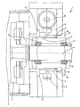
- Fig. 2 discloses the operation according to the prior art mentioned.
- the Shaft 13 is rotatably mounted in a basically fixed housing 14, wherein a sleeve 15 is arranged between the housing wall and the shaft. Within the sleeve rotates the drive shaft 13 freely.
- the sleeve 15 combs itself over External thread 16 with an internal thread of the housing 17th
- a rotation of the sleeve 15 therefore causes the thread pitch that the Sleeve is axially displaced within the housing 14.
- the sleeve 15 is rotatable only when necessary, namely for axial adjustability of the shaft 13 and thus the rotatable working surface 18th
- This rotary movement of the sleeve is brought about by a worm gear.
- Screw 19 arranged tangentially to the sleeve 15, the sleeve outside being a accordingly has teeth 20 with which the worm 19 meshes.
- the axes of screw 19 and sleeve 15 are offset from one another by 90 °.
- Another disadvantage is the complex and therefore expensive manufacture of the sleeve 15 and the housing 14.
- the invention proposes that the adjustment still take place via a To cause axial displacement of the sleeve: this is not done via a Rotational movement of the sleeve, but rather the sleeve is rotatably and according to the invention only axially displaceable. Compared to the generic construction this simplifies the sealing between the shaft, sleeve and housing.
- the adjustment the sleeve is made according to the invention via a thread toothing, with the sleeve on has the outer thread on its outside and an outer component on its inner Surface has the corresponding internal thread.
- thread in the sense of The present proposal describes a complementary design which is described in Depending on a rotational movement of one component, an axial displacement of the other component.
- This "thread” can also be designed without several Threads to be realized, for. B. in the form of a bayonet type Link guide.
- a housing can the shaft, the sleeve and also the rotatable protect the outer component.
- An exemplary embodiment of the invention works with a worm and a worm wheel, which are optimal because of low wear Offer meshing.
- the outer component can advantageously be designed as a ring, that is to say as a comparative one Narrow component, so that a comparatively small installation space due to this arrangement is claimed.
- the rotary drive for the outer component can attack on its outer peripheral surface, for example by a corresponding Toothing on the outside of the rotatable component, for example as Worm drive.
- the outer, for example annular, component is not axial in this case, the worm drive can be moved with a large area Contact surface between the worm and teeth can be formed, for example with concave teeth on the rotatable component, so compared to a generic construction a significantly lower load on this drive occurs in otherwise comparable external conditions and accordingly the operational safety and service life of the proposed Construction is improved.
- a gear drive or a chain drive of the outer component is also provided be, so that depending on the requirements either a particularly inexpensive, a particularly compact or a particularly low-maintenance design can be selected can.
- the drive can also act on the end of the outer rotatable component, for example by means of spur gear or bevel gear teeth. If radial around that rotatable outer component around there is little space available for drive means such a frontal introduction of force radial space around the rotatable outer Component can be saved.
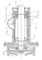
- FIG. 1 generally denotes a compressor, but only is shown in sections. For example, there is a rotating work surface 2 shown, while the associated stator is not shown.
- the work surface 2 is arranged within a compressor chamber 3 and is by a shaft 4th rotatably driven.
- the shaft 4 is rotatably supported within a sleeve 6 via tapered roller bearings 5.
- the Sleeve 6 meshes with a rotatable annular outer component 7.
- This component 7 is formed with a concave Provide drive teeth 9.
- the outer component 7 can therefore be screwed 10 be rotated. Since the outer component 7 at its two axial ends is fixed and thus mounted in both axial directions so that it cannot move during the rotational movement of this component 7 due to the thread pitch of the thread 8 an axial adjustment of the sleeve 6.
- This is rotatably within a key 11 within an outer housing 12 mounted so that the rotational movement by the thread 8 of the outer component 7 is converted into the axial movement of the sleeve 6. It takes the sleeve 6 with the shaft 4 in the axial direction, so that a shaft 4 Adjustment of the rotatable work surface 2 takes place in the axial direction.
- a particular advantage of this exemplary embodiment is the linear tooth engagement the worm 10 forms with the worm gear teeth 9.
- the Support area much larger and thus the material load and the metallic Abrasion reduces what the life of the gearing and the bearings and thus the entire transmission construction significantly extended.
Landscapes
- Engineering & Computer Science (AREA)
- Mechanical Engineering (AREA)
- Environmental & Geological Engineering (AREA)
- Food Science & Technology (AREA)
- Extrusion Moulding Of Plastics Or The Like (AREA)
- Gear Transmission (AREA)
- Separation, Recovery Or Treatment Of Waste Materials Containing Plastics (AREA)
- Transmission Devices (AREA)
Applications Claiming Priority (2)
| Application Number | Priority Date | Filing Date | Title |
|---|---|---|---|
| DE10259102 | 2002-12-18 | ||
| DE2002159102 DE10259102B3 (de) | 2002-12-18 | 2002-12-18 | Verdichter mit verstellbarer Hülse |
Publications (1)
| Publication Number | Publication Date |
|---|---|
| EP1431017A1 true EP1431017A1 (fr) | 2004-06-23 |
Family
ID=31724873
Family Applications (1)
| Application Number | Title | Priority Date | Filing Date |
|---|---|---|---|
| EP03028921A Withdrawn EP1431017A1 (fr) | 2002-12-18 | 2003-12-17 | Compacteur avec manchon réglable |
Country Status (4)
| Country | Link |
|---|---|
| US (1) | US20040213081A1 (fr) |
| EP (1) | EP1431017A1 (fr) |
| JP (1) | JP2004230463A (fr) |
| DE (1) | DE10259102B3 (fr) |
Cited By (1)
| Publication number | Priority date | Publication date | Assignee | Title |
|---|---|---|---|---|
| CN107214341A (zh) * | 2017-05-24 | 2017-09-29 | 大连理工大学 | 一种钢‑耐磨铜合金层状轴瓦材料、其制备装置及制备方法 |
Families Citing this family (3)
| Publication number | Priority date | Publication date | Assignee | Title |
|---|---|---|---|---|
| CA2790574C (fr) * | 2010-02-26 | 2018-04-03 | Strandex Corporation | Production d'articles utiles a partir de dechets |
| CN112517142A (zh) * | 2020-11-17 | 2021-03-19 | 湖南省方圆磨料磨具有限公司 | 一种用于磨料磨具中的旋振筛结构 |
| CN113926528B (zh) * | 2021-09-02 | 2023-03-21 | 厦门市艺述集团有限公司 | 一种园林垃圾回收利用装置及方法 |
Citations (6)
| Publication number | Priority date | Publication date | Assignee | Title |
|---|---|---|---|---|
| DE895095C (de) * | 1941-01-24 | 1953-10-29 | Condux Werk | Verstellvorrichtung fuer Muehlen |
| DE970005C (de) * | 1953-12-29 | 1958-08-07 | Fryma Maschb G M B H | Elektromotorisch angetriebene Muehle |
| US2876958A (en) * | 1955-04-20 | 1959-03-10 | Edwards George Wilfred | Grinding mills and gap adjustment means therefor |
| US2952288A (en) * | 1957-08-02 | 1960-09-13 | Griffith Laboratories | Comminuting machine |
| DE1454875A1 (de) * | 1964-06-17 | 1969-02-06 | Ultrex Chemie Gmbh | Verfahren und Einrichtung zum kontinuierlichen Verschmelzen von thermoplastischen Kunststoffolienabschnitten zu weiterverarbeitbaren granulatfoermigen Teilchen |
| US4062499A (en) * | 1975-10-23 | 1977-12-13 | Philmac Denki Kabushiki Kaisha | Electrical grinding machine for coffee beans |
Family Cites Families (8)
| Publication number | Priority date | Publication date | Assignee | Title |
|---|---|---|---|---|
| US2211518A (en) * | 1934-12-17 | 1940-08-13 | Alexanderwerk Ag | Grinding mill |
| US2716926A (en) * | 1951-01-02 | 1955-09-06 | Jackson And Church Company | Apparatus for treating wood pulp |
| US2852203A (en) * | 1953-11-13 | 1958-09-16 | Ditting | Adjustable grinding disc |
| US3019067A (en) * | 1959-03-10 | 1962-01-30 | Griffith Laboratories | Comminuting machine |
| DE1454873B2 (de) * | 1963-06-29 | 1972-02-10 | Ultrex, Chemie GmbH, 6451 Wolf gang | Verfahren zum kontinuierlichen verdichten von vorzerkleinerten thermoplastischen kunststoffolien bzw kunststoffolienabfaellen |
| DE1291502B (fr) * | 1965-07-20 | 1969-03-27 | ||
| FR2463642A1 (fr) * | 1979-08-21 | 1981-02-27 | Air Liquide | Dispositif de broyage de caoutchouc |
| BG44907A1 (fr) * | 1985-07-19 | 1989-03-15 | Ivan V Genev |
-
2002
- 2002-12-18 DE DE2002159102 patent/DE10259102B3/de not_active Expired - Fee Related
-
2003
- 2003-12-17 US US10/736,604 patent/US20040213081A1/en not_active Abandoned
- 2003-12-17 EP EP03028921A patent/EP1431017A1/fr not_active Withdrawn
- 2003-12-18 JP JP2003421395A patent/JP2004230463A/ja active Pending
Patent Citations (6)
| Publication number | Priority date | Publication date | Assignee | Title |
|---|---|---|---|---|
| DE895095C (de) * | 1941-01-24 | 1953-10-29 | Condux Werk | Verstellvorrichtung fuer Muehlen |
| DE970005C (de) * | 1953-12-29 | 1958-08-07 | Fryma Maschb G M B H | Elektromotorisch angetriebene Muehle |
| US2876958A (en) * | 1955-04-20 | 1959-03-10 | Edwards George Wilfred | Grinding mills and gap adjustment means therefor |
| US2952288A (en) * | 1957-08-02 | 1960-09-13 | Griffith Laboratories | Comminuting machine |
| DE1454875A1 (de) * | 1964-06-17 | 1969-02-06 | Ultrex Chemie Gmbh | Verfahren und Einrichtung zum kontinuierlichen Verschmelzen von thermoplastischen Kunststoffolienabschnitten zu weiterverarbeitbaren granulatfoermigen Teilchen |
| US4062499A (en) * | 1975-10-23 | 1977-12-13 | Philmac Denki Kabushiki Kaisha | Electrical grinding machine for coffee beans |
Cited By (1)
| Publication number | Priority date | Publication date | Assignee | Title |
|---|---|---|---|---|
| CN107214341A (zh) * | 2017-05-24 | 2017-09-29 | 大连理工大学 | 一种钢‑耐磨铜合金层状轴瓦材料、其制备装置及制备方法 |
Also Published As
| Publication number | Publication date |
|---|---|
| DE10259102B3 (de) | 2004-03-18 |
| JP2004230463A (ja) | 2004-08-19 |
| US20040213081A1 (en) | 2004-10-28 |
Similar Documents
| Publication | Publication Date | Title |
|---|---|---|
| EP1434680B1 (fr) | Extrudeuse permettant de produire des matieres fondues plastiques | |
| EP0143414B1 (fr) | Machine à agglomérer | |
| EP0171756B1 (fr) | Extrudeuse à vis | |
| AT410072B (de) | Verfahren und vorrichtung zur einstellung einer vorspannung der messer einer granuliervorrichtung | |
| WO2008055560A1 (fr) | Extrudeuse à plusieurs arbres | |
| WO2005115718A1 (fr) | Unite de fermeture a entrainement a double manivelle | |
| DE4217316A1 (de) | Vorrichtung zum zermahlen von gummi | |
| DE2702390A1 (de) | Vorrichtung zum aufbereiten und strangpressen von thermoplastischen kunststoffen | |
| EP1128941A1 (fr) | Granulat, et procede et dispositif pour sa production | |
| DE1779772A1 (de) | Strangpresse fuer Visko-elastische Kunststoffe und Verfahren zum Plastifizieren und Strangpressen solcher Kunststoffe | |
| EP1431017A1 (fr) | Compacteur avec manchon réglable | |
| WO2005028183A1 (fr) | Groupe d'injection pour presse d'injection | |
| DE10058866B4 (de) | Einspritzaggregat für eine Spritzgiessmaschine | |
| DE3613612C2 (fr) | ||
| DE102008015617B4 (de) | Kollerverstellvorrichtung | |
| DE102005037177A1 (de) | Vorrichtung zum Umwandeln von schüttfähigem wenigstens teilweise thermoplastischem Aufgabegut zu Granulat, Agglomeraten, Pellets, Presslingen und dergleichen | |
| EP1151843A1 (fr) | Unité d'injection pour une machine à mouler par injection | |
| DE4213608C2 (de) | Vorrichtung zum Zerkleinern von Gummibrocken | |
| DE10162076A1 (de) | Mehrfach-Extruderanordnung | |
| DE69112150T2 (de) | Vorrichtung zum Formen eines gebogenen Rohres. | |
| EP0256241A2 (fr) | Dispositif pour le broyage des matières organiques | |
| CH695764A5 (de) | Doppelschneckenpresse. | |
| DE102006014692B3 (de) | Schneckenelement | |
| DE4244312C1 (de) | Schneckenextruder | |
| DE69717417T2 (de) | Extrusionsvorrichtung |
Legal Events
| Date | Code | Title | Description |
|---|---|---|---|
| PUAI | Public reference made under article 153(3) epc to a published international application that has entered the european phase |
Free format text: ORIGINAL CODE: 0009012 |
|
| AK | Designated contracting states |
Kind code of ref document: A1 Designated state(s): AT BE BG CH CY CZ DE DK EE ES FI FR GB GR HU IE IT LI LU MC NL PT RO SE SI SK TR |
|
| AX | Request for extension of the european patent |
Extension state: AL LT LV MK |
|
| 17P | Request for examination filed |
Effective date: 20040911 |
|
| REG | Reference to a national code |
Ref country code: HK Ref legal event code: DE Ref document number: 1064986 Country of ref document: HK |
|
| AKX | Designation fees paid |
Designated state(s): DE FR GB IT NL |
|
| RBV | Designated contracting states (corrected) |
Designated state(s): DE FR GB IT NL |
|
| STAA | Information on the status of an ep patent application or granted ep patent |
Free format text: STATUS: THE APPLICATION IS DEEMED TO BE WITHDRAWN |
|
| 18D | Application deemed to be withdrawn |
Effective date: 20060309 |
|
| REG | Reference to a national code |
Ref country code: HK Ref legal event code: WD Ref document number: 1064986 Country of ref document: HK |