EP1431034A2 - Dispositif de réglage de position d'un corps rotatif à entraínement direct - Google Patents
Dispositif de réglage de position d'un corps rotatif à entraínement direct Download PDFInfo
- Publication number
- EP1431034A2 EP1431034A2 EP03026101A EP03026101A EP1431034A2 EP 1431034 A2 EP1431034 A2 EP 1431034A2 EP 03026101 A EP03026101 A EP 03026101A EP 03026101 A EP03026101 A EP 03026101A EP 1431034 A2 EP1431034 A2 EP 1431034A2
- Authority
- EP
- European Patent Office
- Prior art keywords
- stator
- drive
- rotating body
- axial
- wall
- Prior art date
- Legal status (The legal status is an assumption and is not a legal conclusion. Google has not performed a legal analysis and makes no representation as to the accuracy of the status listed.)
- Granted
Links
- 238000007639 printing Methods 0.000 claims abstract description 25
- 238000005096 rolling process Methods 0.000 claims description 3
- 239000000463 material Substances 0.000 claims description 2
- 238000006073 displacement reaction Methods 0.000 abstract 1
- 230000008878 coupling Effects 0.000 description 5
- 238000010168 coupling process Methods 0.000 description 5
- 238000005859 coupling reaction Methods 0.000 description 5
- 238000007645 offset printing Methods 0.000 description 4
- 230000005291 magnetic effect Effects 0.000 description 3
- 230000001360 synchronised effect Effects 0.000 description 3
- 230000001419 dependent effect Effects 0.000 description 1
- 239000003302 ferromagnetic material Substances 0.000 description 1
- 238000009434 installation Methods 0.000 description 1
- 230000007774 longterm Effects 0.000 description 1
- 239000000758 substrate Substances 0.000 description 1
Images

Classifications
-
- B—PERFORMING OPERATIONS; TRANSPORTING
- B41—PRINTING; LINING MACHINES; TYPEWRITERS; STAMPS
- B41F—PRINTING MACHINES OR PRESSES
- B41F13/00—Common details of rotary presses or machines
- B41F13/08—Cylinders
- B41F13/10—Forme cylinders
- B41F13/12—Registering devices
- B41F13/14—Registering devices with means for displacing the cylinders
-
- B—PERFORMING OPERATIONS; TRANSPORTING
- B41—PRINTING; LINING MACHINES; TYPEWRITERS; STAMPS
- B41F—PRINTING MACHINES OR PRESSES
- B41F13/00—Common details of rotary presses or machines
- B41F13/004—Electric or hydraulic features of drives
- B41F13/0045—Electric driving devices
-
- B—PERFORMING OPERATIONS; TRANSPORTING
- B41—PRINTING; LINING MACHINES; TYPEWRITERS; STAMPS
- B41P—INDEXING SCHEME RELATING TO PRINTING, LINING MACHINES, TYPEWRITERS, AND TO STAMPS
- B41P2213/00—Arrangements for actuating or driving printing presses; Auxiliary devices or processes
- B41P2213/70—Driving devices associated with particular installations or situations
- B41P2213/73—Driving devices for multicolour presses
- B41P2213/734—Driving devices for multicolour presses each printing unit being driven by its own electric motor, i.e. electric shaft
Definitions
- the invention relates to an arrangement of an electric motor for driving a rotating body mounted rotatably on a frame wall, the rotor of the electric motor being arranged rigidly and non-rotatably on the drive shaft of the rotating body for its direct drive, and the stator being supported on the frame wall, the arrangement above all in a printing press, in particular offset printing press, can be used.
- the register-adjustable plate cylinders represent the relevant rotating bodies.
- printing units of offset printing presses are driven by a main drive which distributes its drive power via a mechanical longitudinal shaft or a gear train to the individual units of the printing press and further to the individual cylinders, rollers and drums.
- This mechanical longitudinal coupling connects the printing units to one another in such a way that their synchronous operation with one another is also ensured.
- a complex mechanical system with a variety of different components such. B. gears, couplings, etc. necessary.
- the inevitable synchronization errors due to the backlash, the elasticity of the drive wheel train due to the large inertial masses and the natural vibrations impair the register accuracy and thus the print quality.
- Efforts are therefore known to replace this mechanical coupling between the individual printing units and within the printing units in whole or in part by individual drives on cylinders or decentralized drives on cylinder groups, printing units or printing unit groups and an electronic synchronization of the drives.
- Such an arrangement in printing machines is known for example from DE 41 38 479 A1.
- the rotor / rotating body and stator of the direct drive are in concentric eccentric guides stored, the common adjustment movements by a detachable, preferably mechanical connection are coupled together. Grip both for axial adjustment Eccentric guides on synchronized linear drives.
- the one described there The drive arrangement has the disadvantage that two adjusting means are required for each rotor and stator and that the effort for the synchronization of the parallel adjustment movements is high.
- EP 1 132 202 A1 It is also known from EP 1 132 202 A1 to use plate and rubber blanket cylinders mounted eccentrically in an offset printing press, the stator being fastened to the eccentric bearing ring of the driven cylinder shaft.
- the axial register is adjusted here via a linear motor or a motor-driven spindle, which engages the cylinder shaft and shifts the rotor along the air gap relative to the stator.
- the disadvantage of this is that the spindle acting on the cylinder shaft considerably increases the installation space required for the direct drive.
- the axial actuating device is formed from a disk made of ferromagnetic material which is fixedly arranged on the cylinder drive shaft and on which a magnet coil system fixed to the frame acts.
- the distance between the disk and the coil system and thus the axial position of the displaceably mounted cylinder is changed via the strength of the magnetic field generated.
- the magnetic coil system can be arranged in a unit with the direct drive or separately or on both sides of the cylinder to be adjusted. There is no provision for radial adjustment. Axial adjustment by means of a magnetic field has a resistance-dependent effect, which makes stable positioning difficult.
- the two last-mentioned embodiments for an axial register adjustment require the axial relative mobility of the rotor relative to the stator of a direct drive which is fixed to the frame, for which a particularly complex mounting of the rotor is necessary because of the small air gap between the rotor and stator.
- the invention is therefore based on the object in a direct drive arrangement Maintaining the direct connection between the rotating body and the rotor of the electric motor the adjustment movements for the rotating body transversely and / or longitudinally to its axis of rotation without relative movements between the rotor and stator and reducing the drive stiffness with little effort to synchronize the positioning movements of the rotor and stator to enable.
- the stator is axially positioned by a linear drive (axial register drive), the axial adjustment movements being transmitted from the stator to the rotor and the rotating body via roller bearings which are integrated in the motor and connect the rotor and stator.
- the linear drive is either arranged on the stator or on the frame wall, an additional torque support absorbing the drive or braking torques, or the linear drive itself simultaneously acts as a torque support.
- the constant air gap between the rotor and stator required for a stable operating behavior of the direct drive is advantageously maintained by the forced coupling via roller bearings and is not changed for the compensation of narrowly limited axial and radial adjustment movements of the rotor relative to the stator fixed to the frame.
- a sheetfed offset printing press known per se, several printing units are arranged one behind the other.
- inking unit rollers are arranged in each printing unit, a plate cylinder on which a printing plate is stretched, including a blanket cylinder on which a blanket transmitting the printed image is stretched and underneath a printing cylinder which guides the sheet to be printed.
- All of these rotating bodies are synchronized via a centrally or decentrally driven drive wheel train.
- Individual drives are preferably used on those rotating bodies that often have to implement additional or special movement sequences that are not carried out by the entire printing press.
- z. B plate cylinder rotated into the desired plate changing position by means of separate individual drives.
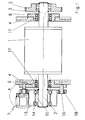
- the exemplary embodiment (FIG. 1) is based on a plate cylinder 1 with an individual drive that is permanently separated from the drive wheel train, the individual drive being designed as a direct drive, ie the rotor 15 of the electric motor is arranged directly and in a fixed manner on the drive shaft 2 of the plate cylinder 1.
- the plate cylinder shaft 3 is extended beyond the bearing 17 in the frame wall 4 and carries a loose gear wheel 5, which is roller-mounted on the shaft 3 and which transmits the drive torque from the blanket cylinder to the inking unit to the driven inking unit rollers within the gear train to influence the independent rotation of the plate cylinder 1.
- the drive shaft 2 of the plate cylinder 1 is rotatably mounted in the wall 4 in a ball bearing 17.
- the ball bearing 17 is directly encompassed by an eccentric bush 6, which is mounted in the printing unit wall 4. If the eccentric bushing 6 is rotated, the axis of rotation of the drive shaft 2 moves in an eccentric orbit.
- eccentric bushes - bearings on both sides of the plate cylinder 1 the diagonal register can be adjusted.
- the plate cylinder 1 is mounted in the longitudinal direction in a known manner by means of bearings 17 in the frame walls 4.
- an axial register drive 7 with a holder 19 is fixedly arranged directly on the stator 13.
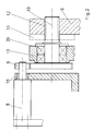
- the axial register drive 7 can be, for example, a servo motor 8 with a spur gear reduction gear 9, which drives a traction spindle 10 which engages in the eccentric bush 6 on the drive side (FIG. 2).
- the tension spindle 10 is guided in bearings 20 in an outer ring comprising the stator 13 or in a lever fastened to the stator 13.
- stator 13 and rotor 15 of the plate cylinder direct drive are connected concentrically to one another by means of high-quality roller bearings 14, in particular axial bearings (FIG. 1).
- the torsion-resistant arrangement of the stator 13 for receiving the drive and braking torque is achieved by at least one torque support 16 arranged on the circumference of the stator 13, which is formed by a bolt which is mounted axially parallel in the eccentric bushing 6 and without play in a bore in the The outer ring of the stator housing engages.
- the bolt can be guided in the bore with sliding or rolling bearings (18).
- the overturning moment generated by the axial register motor 8 in the drive shaft 2 of the plate cylinder 1 is optimally reduced if the plate cylinder 1 rotates during the axial actuating movement and thus the axial movement of the cylinder shaft 2, 3 takes place in the bearings 17 with minimal friction.
- the pulling spindle 10 engaging in the threaded bore 12 can be countered by an additional lock nut 11 without play.
- the direct drive in the axial register adjustment according to the invention does not have a frame-fixed connection of the stator 13 to the wall 4 like known drive variants, it must be fixed so stiffly in its rotational angle position relative to the eccentric bush 6 in spite of its axial mobility that no circumferential register deviations occur.
- the already mentioned at least one torque support 16 is used, which prevents the stator 13 from rotating relative to the eccentric bushing 6 by guiding the stator 13 on an axially parallel bolt fastened in the eccentric bushing 6.
- the traction spindle 10 itself can also be designed as a torque support with appropriate play-free mounting 20 and dimensioning.
- the axial register drive 7 is not arranged on the stator 13, but on the wall 4 outside the eccentric bushing 6 (FIG. 3).
- the tension spindle 10 is in this case guided in the wall 4 in play-free bearings 20, the dimensions and spacing of which must take into account the additional function of the tension spindle 10 as a torque support.
- the axial register motor 8 is mounted on the wall 4 outside the eccentric bushing 6 with the aid of a bracket 19 and drives the feed screw 10 via the reduction gear 9.
- the reduction gear 9 consists of a spur gear on the motor shaft and on the tension spindle 10, which mesh with one another.
- the tension spindle 10 engages in a slide piece 21 with a corresponding internal thread, which is guided without play in an elongated hole guide 22 in the outer ring of the stator 13 or in a lever fixedly attached to the stator 13.
- the axial register motor 8 is now activated in a manner analogous to the first exemplary embodiment, which sets the traction spindle 10 in rotation in the intended direction via the reduction gear 9.
- the spindle rotation is converted into an axially parallel linear movement, the slider 21 transmitting the linear adjustment movement to the stator 13 and, via the motor-integrated bearings 14, to the rotor-plate cylinder assembly 13, 15.
- the slot guide 22 serves to compensate for the radial adjustment of the drive shaft 2 of the plate cylinder 1 (diagonal register). Since the axial register drive 7 is fixedly arranged on the frame wall 4 and, in contrast to the first exemplary embodiment, not the stator 13 and the axial register drive 7 are adjusted together with the eccentric bush 6, but only the stator 13, a radial relative movement occurs between the stator 13 and the axial register drive 7 when the Eccentric bush 6 on. The resulting change in distance between the stator 13 and the spindle 10 is compensated for with the slot guide 22 of the slider 21.
- the rotary movement of the stator 13 caused by the eccentric rotation must be known Means captured by the machine control and compensated by the direct drive 13.15 to a deviation of the rotational angle position of the rotor 15 from its target position and thereby prevent the print image from shifting on the printing substrate.
- the eccentric bushing 6 is omitted and the tension spindle 10 engages in a threaded bore 12 in the wall 4 when the axial register drive 7 is arranged on the stator 13 of the direct drive.
- the axial register drive 7 is arranged on the wall 4, the guidance of the tension spindle 10 on the stator 13 is simplified because of the lack of the radial relative movement between the direct drive and the wall 4 to form a threaded bore.
Landscapes
- Engineering & Computer Science (AREA)
- Mechanical Engineering (AREA)
- Rotary Presses (AREA)
- Permanent Magnet Type Synchronous Machine (AREA)
- Motor Or Generator Frames (AREA)
- Connection Of Motors, Electrical Generators, Mechanical Devices, And The Like (AREA)
Applications Claiming Priority (2)
| Application Number | Priority Date | Filing Date | Title |
|---|---|---|---|
| DE10260491 | 2002-12-21 | ||
| DE2002160491 DE10260491A1 (de) | 2002-12-21 | 2002-12-21 | Vorrichtung zur Lageverstellung eines Drehkörpers mit Direktantrieb |
Publications (3)
| Publication Number | Publication Date |
|---|---|
| EP1431034A2 true EP1431034A2 (fr) | 2004-06-23 |
| EP1431034A3 EP1431034A3 (fr) | 2004-09-15 |
| EP1431034B1 EP1431034B1 (fr) | 2006-02-15 |
Family
ID=32336568
Family Applications (1)
| Application Number | Title | Priority Date | Filing Date |
|---|---|---|---|
| EP20030026101 Expired - Lifetime EP1431034B1 (fr) | 2002-12-21 | 2003-11-13 | Dispositif de réglage de position d'un corps rotatif à entraînement direct |
Country Status (2)
| Country | Link |
|---|---|
| EP (1) | EP1431034B1 (fr) |
| DE (2) | DE10260491A1 (fr) |
Cited By (7)
| Publication number | Priority date | Publication date | Assignee | Title |
|---|---|---|---|---|
| DE102004048315A1 (de) * | 2004-10-05 | 2006-04-06 | Man Roland Druckmaschinen Ag | Druckeinheit einer Druckmaschine und Verfahren zur Durchführung eines Druckplattenwechsels an einem Formzylinder einer Druckeinheit |
| EP1777068A2 (fr) | 2005-10-20 | 2007-04-25 | Schaeffler KG | Entraînement direct d'une machine d'impression |
| EP1724113A3 (fr) * | 2005-05-20 | 2010-03-17 | Komori Corporation | Dispositif pour supporter une structure cylindrique |
| EP1920925A3 (fr) * | 2006-11-09 | 2010-12-22 | Robert Bosch Gmbh | Entraînement à prise directe |
| EP2067619A3 (fr) * | 2007-12-04 | 2011-08-10 | manroland AG | Procédé et entraînement pour entraîner une machine de traitement de matériau en feuilles |
| WO2018120377A1 (fr) * | 2016-12-27 | 2018-07-05 | 长胜纺织科技发展(上海)有限公司 | Système d'enregistrement horizontal |
| CN111204113A (zh) * | 2020-03-14 | 2020-05-29 | 渭南科赛机电设备有限责任公司 | 一种电子轴凹版印刷机横向快速对版的方法 |
Families Citing this family (2)
| Publication number | Priority date | Publication date | Assignee | Title |
|---|---|---|---|---|
| DE102006042210A1 (de) * | 2006-09-08 | 2008-03-27 | Man Roland Druckmaschinen Ag | Angetriebene Einheit einer Druckmaschine |
| DE102008042939B4 (de) | 2008-10-17 | 2021-01-21 | Koenig & Bauer Ag | Direktantrieb mit axialer Lageverstellung |
Citations (3)
| Publication number | Priority date | Publication date | Assignee | Title |
|---|---|---|---|---|
| DE4138479A1 (de) | 1991-11-22 | 1993-06-03 | Baumueller Nuernberg Gmbh | Verfahren und anordnung fuer einen elektromotor zum antrieb eines drehkoerpers, insbesondere des druckgebenden zylinders einer druckmaschine |
| DE19903847A1 (de) | 1999-02-01 | 2000-08-03 | Roland Man Druckmasch | Vorrichtung zum axialen Führen und Verstellen eines Zylinders |
| EP1132202A1 (fr) | 1994-08-30 | 2001-09-12 | MAN Roland Druckmaschinen AG | Machine d'impression offset |
Family Cites Families (7)
| Publication number | Priority date | Publication date | Assignee | Title |
|---|---|---|---|---|
| DE4322744C2 (de) * | 1993-07-08 | 1998-08-27 | Baumueller Nuernberg Gmbh | Elektrisches Antriebssystem und Positionierverfahren zur synchronen Verstellung mehrerer dreh- und/oder verschwenkbarer Funktionsteile in Geräten und Maschinen, Antriebsanordnung mit einem Winkellagegeber und Druckmaschine |
| DE4422097A1 (de) * | 1994-06-24 | 1996-01-04 | Roland Man Druckmasch | Anordnung eines Elektromotors zum Antrieb eines Drehkörpers |
| DE19521827A1 (de) * | 1995-06-16 | 1996-12-19 | Roland Man Druckmasch | Druckmaschinen-Direktantrieb |
| JP3357074B2 (ja) * | 1996-08-09 | 2002-12-16 | ケーニツヒ ウント バウエル アクチエンゲゼルシヤフト | 胴駆動装置 |
| JP3448766B2 (ja) * | 2000-06-07 | 2003-09-22 | 株式会社東京機械製作所 | 多色輪転印刷機の見当調整装置 |
| JP2001347632A (ja) * | 2000-06-09 | 2001-12-18 | Dainippon Printing Co Ltd | サイドレーおよび輪転印刷機 |
| JP2002210915A (ja) * | 2001-01-22 | 2002-07-31 | Tokyo Kikai Seisakusho Ltd | 分割版胴を個別に駆動する多色刷平版印刷機 |
-
2002
- 2002-12-21 DE DE2002160491 patent/DE10260491A1/de not_active Withdrawn
-
2003
- 2003-11-13 EP EP20030026101 patent/EP1431034B1/fr not_active Expired - Lifetime
- 2003-11-13 DE DE50302416T patent/DE50302416D1/de not_active Expired - Lifetime
Patent Citations (3)
| Publication number | Priority date | Publication date | Assignee | Title |
|---|---|---|---|---|
| DE4138479A1 (de) | 1991-11-22 | 1993-06-03 | Baumueller Nuernberg Gmbh | Verfahren und anordnung fuer einen elektromotor zum antrieb eines drehkoerpers, insbesondere des druckgebenden zylinders einer druckmaschine |
| EP1132202A1 (fr) | 1994-08-30 | 2001-09-12 | MAN Roland Druckmaschinen AG | Machine d'impression offset |
| DE19903847A1 (de) | 1999-02-01 | 2000-08-03 | Roland Man Druckmasch | Vorrichtung zum axialen Führen und Verstellen eines Zylinders |
Cited By (11)
| Publication number | Priority date | Publication date | Assignee | Title |
|---|---|---|---|---|
| DE102004048315A1 (de) * | 2004-10-05 | 2006-04-06 | Man Roland Druckmaschinen Ag | Druckeinheit einer Druckmaschine und Verfahren zur Durchführung eines Druckplattenwechsels an einem Formzylinder einer Druckeinheit |
| US7497163B2 (en) | 2004-10-05 | 2009-03-03 | Man Roland Druckmaschinen Ag | Printing unit of a printing press and method for carrying out a printing-plate change on a forme cylinder of a printing unit |
| EP1724113A3 (fr) * | 2005-05-20 | 2010-03-17 | Komori Corporation | Dispositif pour supporter une structure cylindrique |
| RU2401203C2 (ru) * | 2005-05-20 | 2010-10-10 | Комори Корпорейшн | Опорное устройство цилиндрического тела |
| US7814829B2 (en) | 2005-05-20 | 2010-10-19 | Komori Corporation | Cylindrical body supporting device |
| EP1777068A2 (fr) | 2005-10-20 | 2007-04-25 | Schaeffler KG | Entraînement direct d'une machine d'impression |
| EP1777068A3 (fr) * | 2005-10-20 | 2008-01-23 | Schaeffler KG | Entraînement direct d'une machine d'impression |
| EP1920925A3 (fr) * | 2006-11-09 | 2010-12-22 | Robert Bosch Gmbh | Entraînement à prise directe |
| EP2067619A3 (fr) * | 2007-12-04 | 2011-08-10 | manroland AG | Procédé et entraînement pour entraîner une machine de traitement de matériau en feuilles |
| WO2018120377A1 (fr) * | 2016-12-27 | 2018-07-05 | 长胜纺织科技发展(上海)有限公司 | Système d'enregistrement horizontal |
| CN111204113A (zh) * | 2020-03-14 | 2020-05-29 | 渭南科赛机电设备有限责任公司 | 一种电子轴凹版印刷机横向快速对版的方法 |
Also Published As
| Publication number | Publication date |
|---|---|
| DE50302416D1 (de) | 2006-04-20 |
| DE10260491A1 (de) | 2004-07-01 |
| EP1431034A3 (fr) | 2004-09-15 |
| EP1431034B1 (fr) | 2006-02-15 |
Similar Documents
| Publication | Publication Date | Title |
|---|---|---|
| DE4138479C2 (de) | Verfahren und Anordnung für einen Elektromotor zum Antrieb eines Drehkörpers, insbesondere des druckgebenden Zylinders einer Druckmaschine | |
| EP0741015B1 (fr) | Dispositif pour régler la position circonférentielle et latérale du cylindre porte-plaque | |
| EP0438716A2 (fr) | Dispositif pour actionner des tréteaux de support d'arbres | |
| EP0981443B1 (fr) | Dispositif d'entrainement pour composant tournant d'une rotative | |
| EP0802048B1 (fr) | Capteur de rotation pour un cylindre d'une machine à imprimer | |
| EP1431034B1 (fr) | Dispositif de réglage de position d'un corps rotatif à entraînement direct | |
| EP0921946B2 (fr) | Entrainement de cylindre | |
| DE4143597C2 (de) | Druckmaschine mit wenigstens einem elektromotorisch angetriebenen, axial verstellbaren Zylinder oder sonstigen Drehkörper | |
| DE10327218B4 (de) | Direktantrieb für einen Zylinder einer Druckmaschine | |
| EP0722831B1 (fr) | Procédé et arrangement pour un moteur électrique pour entraíner un corps de rotation, en particulier un cylindre d'imprimerie | |
| EP0405249B1 (fr) | Dispositif pour régler le registre circonférentiel | |
| EP1372964B1 (fr) | Entrainement d'un groupe d'impression | |
| DE102005047661B4 (de) | Antrieb eines rotierenden Bauteils einer Druckmaschine | |
| DE102005061028A1 (de) | Antriebe einer oder zweier Walzen | |
| DE102008042939B4 (de) | Direktantrieb mit axialer Lageverstellung | |
| DE10331605B3 (de) | Verstellbar gelagerte Walze | |
| EP2490894B1 (fr) | Dispositifs dans un groupe imprimant d'une machine d'impression | |
| DE4101823C2 (de) | Antriebsraederzug | |
| DE102005029969A1 (de) | Anordnung von Drehwinkelgebern | |
| DE102004022775B4 (de) | Anordnung eines Elektromotors zum Antrieb eines Drehkörpers | |
| DE4139326C2 (de) | Vorrichtung zum Einstellen des Umfangsregisters an Rotationsdruckmaschinen | |
| EP1392510B1 (fr) | Procede et dispositif de reglage de registre | |
| DE102004022774B4 (de) | Anordnung eines Elektromotors zum Antrieb eines Zylinders einer Rotationsdruckmaschine | |
| DE10114806A1 (de) | Antrieb eines Zylinders | |
| DE102022102028A1 (de) | Verarbeitungswerk und Verfahren zum Betreiben eines Verarbeitungswerkes einer Verarbeitungsmaschine |
Legal Events
| Date | Code | Title | Description |
|---|---|---|---|
| PUAI | Public reference made under article 153(3) epc to a published international application that has entered the european phase |
Free format text: ORIGINAL CODE: 0009012 |
|
| AK | Designated contracting states |
Kind code of ref document: A2 Designated state(s): AT BE BG CH CY CZ DE DK EE ES FI FR GB GR HU IE IT LI LU MC NL PT RO SE SI SK TR |
|
| AX | Request for extension of the european patent |
Extension state: AL LT LV MK |
|
| PUAL | Search report despatched |
Free format text: ORIGINAL CODE: 0009013 |
|
| AK | Designated contracting states |
Kind code of ref document: A3 Designated state(s): AT BE BG CH CY CZ DE DK EE ES FI FR GB GR HU IE IT LI LU MC NL PT RO SE SI SK TR |
|
| AX | Request for extension of the european patent |
Extension state: AL LT LV MK |
|
| RIC1 | Information provided on ipc code assigned before grant |
Ipc: 7B 41F 13/004 B Ipc: 7B 41F 21/10 A |
|
| 17P | Request for examination filed |
Effective date: 20041127 |
|
| 17Q | First examination report despatched |
Effective date: 20050315 |
|
| AKX | Designation fees paid |
Designated state(s): DE FR GB IT |
|
| GRAP | Despatch of communication of intention to grant a patent |
Free format text: ORIGINAL CODE: EPIDOSNIGR1 |
|
| GRAS | Grant fee paid |
Free format text: ORIGINAL CODE: EPIDOSNIGR3 |
|
| GRAA | (expected) grant |
Free format text: ORIGINAL CODE: 0009210 |
|
| AK | Designated contracting states |
Kind code of ref document: B1 Designated state(s): DE FR GB IT |
|
| PG25 | Lapsed in a contracting state [announced via postgrant information from national office to epo] |
Ref country code: IT Free format text: LAPSE BECAUSE OF FAILURE TO SUBMIT A TRANSLATION OF THE DESCRIPTION OR TO PAY THE FEE WITHIN THE PRESCRIBED TIME-LIMIT;WARNING: LAPSES OF ITALIAN PATENTS WITH EFFECTIVE DATE BEFORE 2007 MAY HAVE OCCURRED AT ANY TIME BEFORE 2007. THE CORRECT EFFECTIVE DATE MAY BE DIFFERENT FROM THE ONE RECORDED. Effective date: 20060215 |
|
| REG | Reference to a national code |
Ref country code: GB Ref legal event code: FG4D Free format text: NOT ENGLISH |
|
| REF | Corresponds to: |
Ref document number: 50302416 Country of ref document: DE Date of ref document: 20060420 Kind code of ref document: P |
|
| GBT | Gb: translation of ep patent filed (gb section 77(6)(a)/1977) |
Effective date: 20060523 |
|
| ET | Fr: translation filed | ||
| PLBE | No opposition filed within time limit |
Free format text: ORIGINAL CODE: 0009261 |
|
| STAA | Information on the status of an ep patent application or granted ep patent |
Free format text: STATUS: NO OPPOSITION FILED WITHIN TIME LIMIT |
|
| 26N | No opposition filed |
Effective date: 20061116 |
|
| PGFP | Annual fee paid to national office [announced via postgrant information from national office to epo] |
Ref country code: DE Payment date: 20131128 Year of fee payment: 11 Ref country code: GB Payment date: 20131120 Year of fee payment: 11 Ref country code: FR Payment date: 20131120 Year of fee payment: 11 |
|
| PGFP | Annual fee paid to national office [announced via postgrant information from national office to epo] |
Ref country code: IT Payment date: 20131127 Year of fee payment: 11 |
|
| REG | Reference to a national code |
Ref country code: DE Ref legal event code: R119 Ref document number: 50302416 Country of ref document: DE |
|
| GBPC | Gb: european patent ceased through non-payment of renewal fee |
Effective date: 20141113 |
|
| REG | Reference to a national code |
Ref country code: FR Ref legal event code: ST Effective date: 20150731 |
|
| PG25 | Lapsed in a contracting state [announced via postgrant information from national office to epo] |
Ref country code: GB Free format text: LAPSE BECAUSE OF NON-PAYMENT OF DUE FEES Effective date: 20141113 Ref country code: DE Free format text: LAPSE BECAUSE OF NON-PAYMENT OF DUE FEES Effective date: 20150602 |
|
| PG25 | Lapsed in a contracting state [announced via postgrant information from national office to epo] |
Ref country code: FR Free format text: LAPSE BECAUSE OF NON-PAYMENT OF DUE FEES Effective date: 20141201 |
|
| PG25 | Lapsed in a contracting state [announced via postgrant information from national office to epo] |
Ref country code: IT Free format text: LAPSE BECAUSE OF NON-PAYMENT OF DUE FEES Effective date: 20141113 |