EP1431118A2 - Aktuator für Scheinwerfer - Google Patents
Aktuator für Scheinwerfer Download PDFInfo
- Publication number
- EP1431118A2 EP1431118A2 EP03405750A EP03405750A EP1431118A2 EP 1431118 A2 EP1431118 A2 EP 1431118A2 EP 03405750 A EP03405750 A EP 03405750A EP 03405750 A EP03405750 A EP 03405750A EP 1431118 A2 EP1431118 A2 EP 1431118A2
- Authority
- EP
- European Patent Office
- Prior art keywords
- actuator
- projector
- motor
- gears
- headlight
- Prior art date
- Legal status (The legal status is an assumption and is not a legal conclusion. Google has not performed a legal analysis and makes no representation as to the accuracy of the status listed.)
- Withdrawn
Links
- 230000009467 reduction Effects 0.000 claims description 3
- XEEYBQQBJWHFJM-UHFFFAOYSA-N Iron Chemical group [Fe] XEEYBQQBJWHFJM-UHFFFAOYSA-N 0.000 claims description 2
- 230000008878 coupling Effects 0.000 description 4
- 238000010168 coupling process Methods 0.000 description 4
- 238000005859 coupling reaction Methods 0.000 description 4
- 230000007935 neutral effect Effects 0.000 description 4
- 230000000694 effects Effects 0.000 description 2
- 230000007246 mechanism Effects 0.000 description 2
- 239000000523 sample Substances 0.000 description 2
- 230000009466 transformation Effects 0.000 description 2
- 230000005355 Hall effect Effects 0.000 description 1
- 230000008859 change Effects 0.000 description 1
- 239000003638 chemical reducing agent Substances 0.000 description 1
- 238000004891 communication Methods 0.000 description 1
- 238000010276 construction Methods 0.000 description 1
- 230000001419 dependent effect Effects 0.000 description 1
- 238000006073 displacement reaction Methods 0.000 description 1
- 230000004313 glare Effects 0.000 description 1
- 238000004519 manufacturing process Methods 0.000 description 1
- 238000000034 method Methods 0.000 description 1
- 230000004048 modification Effects 0.000 description 1
- 238000012986 modification Methods 0.000 description 1
- 230000003287 optical effect Effects 0.000 description 1
- 230000010355 oscillation Effects 0.000 description 1
- 238000007639 printing Methods 0.000 description 1
- 230000008569 process Effects 0.000 description 1
- 238000005096 rolling process Methods 0.000 description 1
Images


Classifications
-
- B—PERFORMING OPERATIONS; TRANSPORTING
- B60—VEHICLES IN GENERAL
- B60Q—ARRANGEMENT OF SIGNALLING OR LIGHTING DEVICES, THE MOUNTING OR SUPPORTING THEREOF OR CIRCUITS THEREFOR, FOR VEHICLES IN GENERAL
- B60Q1/00—Arrangement of optical signalling or lighting devices, the mounting or supporting thereof or circuits therefor
- B60Q1/02—Arrangement of optical signalling or lighting devices, the mounting or supporting thereof or circuits therefor the devices being primarily intended to illuminate the way ahead or to illuminate other areas of way or environments
- B60Q1/04—Arrangement of optical signalling or lighting devices, the mounting or supporting thereof or circuits therefor the devices being primarily intended to illuminate the way ahead or to illuminate other areas of way or environments the devices being headlights
- B60Q1/06—Arrangement of optical signalling or lighting devices, the mounting or supporting thereof or circuits therefor the devices being primarily intended to illuminate the way ahead or to illuminate other areas of way or environments the devices being headlights adjustable, e.g. remotely-controlled from inside vehicle
- B60Q1/076—Arrangement of optical signalling or lighting devices, the mounting or supporting thereof or circuits therefor the devices being primarily intended to illuminate the way ahead or to illuminate other areas of way or environments the devices being headlights adjustable, e.g. remotely-controlled from inside vehicle by electrical means including means to transmit the movements, e.g. shafts or joints
-
- B—PERFORMING OPERATIONS; TRANSPORTING
- B60—VEHICLES IN GENERAL
- B60Q—ARRANGEMENT OF SIGNALLING OR LIGHTING DEVICES, THE MOUNTING OR SUPPORTING THEREOF OR CIRCUITS THEREFOR, FOR VEHICLES IN GENERAL
- B60Q1/00—Arrangement of optical signalling or lighting devices, the mounting or supporting thereof or circuits therefor
- B60Q1/02—Arrangement of optical signalling or lighting devices, the mounting or supporting thereof or circuits therefor the devices being primarily intended to illuminate the way ahead or to illuminate other areas of way or environments
- B60Q1/04—Arrangement of optical signalling or lighting devices, the mounting or supporting thereof or circuits therefor the devices being primarily intended to illuminate the way ahead or to illuminate other areas of way or environments the devices being headlights
- B60Q1/06—Arrangement of optical signalling or lighting devices, the mounting or supporting thereof or circuits therefor the devices being primarily intended to illuminate the way ahead or to illuminate other areas of way or environments the devices being headlights adjustable, e.g. remotely-controlled from inside vehicle
- B60Q1/08—Arrangement of optical signalling or lighting devices, the mounting or supporting thereof or circuits therefor the devices being primarily intended to illuminate the way ahead or to illuminate other areas of way or environments the devices being headlights adjustable, e.g. remotely-controlled from inside vehicle automatically
- B60Q1/12—Arrangement of optical signalling or lighting devices, the mounting or supporting thereof or circuits therefor the devices being primarily intended to illuminate the way ahead or to illuminate other areas of way or environments the devices being headlights adjustable, e.g. remotely-controlled from inside vehicle automatically due to steering position
-
- B—PERFORMING OPERATIONS; TRANSPORTING
- B60—VEHICLES IN GENERAL
- B60Q—ARRANGEMENT OF SIGNALLING OR LIGHTING DEVICES, THE MOUNTING OR SUPPORTING THEREOF OR CIRCUITS THEREFOR, FOR VEHICLES IN GENERAL
- B60Q2200/00—Special features or arrangements of vehicle headlamps
- B60Q2200/30—Special arrangements for adjusting headlamps, e.g. means for transmitting the movements for adjusting the lamps
- B60Q2200/38—Automatic calibration of motor-driven means for adjusting headlamps, i.e. when switching on the headlamps, not during mounting at factories
Definitions
- the present invention relates to an actuator for a headlight unit, in particular for a vehicle, according to the preamble of claim 1.
- a mechanism must be used to position the projector with the desired angle and thus obtain the lighting of the curve.
- This positioning mechanism must also ability to return projector precisely to position initial or middle position, i.e. redirect it in the direction of travel, when the vehicle is traveling in line right, this to avoid glare from traffic coming reverse.
- this function projector orientation is referred to by the simple term "Horizontal orientation function”.
- a midpoint detector is used to monitor the angular position of the projector and serves as a reference for determine the position of the latter. This reference can be used for setting the initial angle of the system. It is also possible to define several points of reference with several functions.
- the object of the invention is to provide an actuator for headlight unit easier to integrate into this unit subsidiary and which overcomes the disadvantages encountered with known discrete elements.
- the headlight unit - hereinafter referred to as "headlight" - is formed of an assembly comprising a projector integrating a means luminous and an actuator provided with a support.
- the projector is mechanically coupled to the actuator so as to have a pivoting ability in a so-called horizontal plane. Thanks to the support which includes fixing means, this together can be integrated into the construction of a car almost like a conventional headlight, while allowing the projector an ability to move lateral, i.e. in the horizontal plane.
- the actuator integrates monolithically all the functions necessary for a horizontal pivoting movement. It is therefore no longer necessary to mount several discrete components and connect to get orientation function horizontal.
- the projector is simply mechanically linked to the actuator by a backlash-free coupling.
- a variant consists in integrating two motors in the the actuator.
- One of the motors controls the orientation lateral (or angular) of the projector as mentioned above, the other its orientation in a vertical plane.
- Vertical orientation is used to adjust the range of the beam of light generated by the projector. This function already exists, but is performed by an actuator separate, with the disadvantages already mentioned.
- the actuator with integrated electronics and communication by bus, it offers an easier use for the car manufacturer: the latter must not know the rules for driving the engine or deal with sensor information. He just has to send standardized orders which will be processed and executed by the actuator.
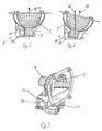
- Figures 1-5 show a first example of a lighthouse 1 or a headlight unit according to the invention.
- the projector 5 On a support 3 is arranged the projector 5 with the light means including only the socket 9 is visible.
- Projector 5 is arranged on a shaft 11 which passes through the housing of the actuator, which shaft is housed inside this latest.
- the projector 5 is constructed and fixed to the shaft 11 so other fixing is not required, but advantageous.
- a second attachment allowing pivoting, in particular arranged in the pivot axis diametrically opposite to the attachment to the actuator, is provided to stabilize the headlamp with regard to vibrations and shaking which occur while using a vehicle.
- the entire headlight unit can be mounted in a case.
- This box can be placed in the chassis or body of the vehicle, practically like a traditional headlight, except for the connector intended for supply power and control signals to the actuator.
- the connector intended for supply power and control signals to the actuator.
- the projector (or source 5) can rotate right and left.
- Figure 1 shows the source in an upright position, indicated by the line 16 coinciding with arrow 17 indicating the orientation of the projector.
- Figure 2 shows the position of the lighthouse where the lights are directed to the right in a marked direction by arrow 18.
- the shaft 11 of the projector 5 passes through a cuff 20 to which it is attached, or in which it is inserted and held by the weight of the projector 5. Thanks to the section of the shaft 11, for example polygonal, and of the hole in the cuff 20, the two elements, shaft and cuff, are linked in rotation relative to each other.
- the sleeve 20 is mounted on a rotating plate 3 housed in a housing 13 of the actuator 14. At the periphery of the plate there is a toothing 22, in which the front part of a toothed wheel 23. The rear part of this toothed wheel 23, which has a greater number of teeth, meshes in the worm screw 25 with helical teeth extending the drive shaft of an electric motor 27.
- This arrangement of toothed wheels constitutes a reduction gear with gear train.
- the projector 5 can be repositioned in a plane horizontal to the right or to the left, i.e. in a plane parallel to the base of the housing and to the plate support 3.
- Fixing and guiding the reflector or spotlight 5 must be made to ensure minimum play, in order to prevent the vibrations produced by the rolling of the car produces oscillations of the light beam.
- these teeth are conical and pretensioned.
- the part front of the toothed wheel 23 is produced in the form of a bevel gear 24, and additionally, the toothing 22 of the rotary plate 3 is also conical.
- a spring 27 exerts a force on the rear face of the shaft 29 of the toothed wheel 23. This force pushes the bevel gear 24 towards the top of the toothing 22, at the same time reducing the play of this bevel gear almost to zero.
- a clearance between the worm 25 and the toothed wheel 23 is minimum thanks to a precise arrangement of the motor in relation to the toothed wheel 23. To this end, it would also be possible to press the motor, or rather the worm 25, against the wheel 23.
- the electrical energy for the motor 26 is supplied by the control circuit 28 made as a printed circuit.
- This circuit 28 is able to respond to digital commands received from the outside and activate the motor 26 so suitable for the spotlight 5 to be directed into a direction defined by numerical control.
- the control circuit can straighten the projector by neutral position or middle position, where the beam of light is projected straight (line 16 in figure 1) relative to the housing 13.
- a magnet 30 is fixed on the rotary plate 3
- a magnetosensitive sensor 32 with effect Hall placed so that the distance or distance between the sensor 32 and the magnet is minimal when the projector is in upright position.
- control circuit 28 can therefore determine the neutral position.
- the motor shaft 26 performs a number of turns.
- the motor 26 is preferably of the step-by-step type, but any other kind of motor or device allowing exact control, is usable, for example with a means of measuring rotation integrated.
- one of the cogwheels or any other element moving during change of direction of the projector may be provided with a means of measuring angular displacement.
- At least a magnet and at least one sensor are provided, so as to allow the positions of the magnets relative to those sensors provide optional digital coding of the positioning.
- connections to provide power to the circuit control and connection for control signals digital for example in the form of a bus connection or internal digital network of a car (cf. arrangement 34 of connection terminals, Figures 4 and 6).
- Figures 6 and 7 show a second embodiment, this allowing adjustment of the projector in the plane vertical.
- the unit includes a second motor 38 provided with a vertical rod 40 and is housed with a ability to pivot around eye 42 in the chassis of a car. By moving the end of the rod 40, it is possible to adjust the vertical tilt of the headlight and therefore the range of the light beam. Obviously, this inclination will likewise be controlled by the circuit of command 28 and chosen from the outside by the connection above.
- the headlight unit described can be integrated into a car basically like a headlight conventional, and for lateral direction control, it is simply necessary to connect it to a system of digital control.
- the lighthouse returns to position neutral either on simple command, or automatically.
- a coil with a soft iron core In the case 13 is fixed an identical component. In the middle position, the two cores are aligned and the electromagnetic coupling between the two coils is maximum. During a trip angle of the movable part 3 a decrease in the coupling between the two coils caused by non-alignment nuclei.
- Integrated electronics measure electromagnetic coupling by sending pulses electrical in one of the coils and measuring the voltage induced in the other coil. The electronics deduce the angular position.
- FIG. 8 An alternative embodiment shown in Figures 8 and 9 is base on an actuator 14 using a linear movement to rotate the projector 5 about its axis vertical via a lever 46.
- Figure 8 shows the motor 26, here provided with a movement shaft 48 linear.
- the shaft 48 engages in the lever 46 of a articulated way, for example by means of a ball joint.
- Lever 48 is functionally linked with the pivotable projector housing 5.
- the lever can be attached to the turntable 3 or directly to the cuff 20.
- the rear end 50 of the motor shaft 26 is provided with an arm 52.
- the arm 52 carries a permanent magnet 55.
- a sensor 56 sensitive to the field magnetic eg a Hall sensor, is arranged in such a way that the magnet 55 passes below the sensor 56 when the shaft of the motor 26 turns.
- the sensor is mounted on one side of the integrated circuit 28, which significantly facilitates the production and assembly.
- the electronic control can determine the position of the motor 26 and therefore the angular position of the projector 5, particularly the middle position. In the simplest case, less than one turn of engine 26 is sufficient to cover the total range of angular movement of the projector. Therefore, the position closest to the magnet relative to the sensor 56 means an unambiguous angular position of reference.
- This embodiment also has the same structure as those described above.
- the motor 26 is preferably a stepper motor, which allows accurately control the position of the projector.
Landscapes
- Engineering & Computer Science (AREA)
- Mechanical Engineering (AREA)
- Lighting Device Outwards From Vehicle And Optical Signal (AREA)
Applications Claiming Priority (2)
| Application Number | Priority Date | Filing Date | Title |
|---|---|---|---|
| CH20022145 | 2002-12-17 | ||
| CH21452002 | 2002-12-17 |
Publications (2)
| Publication Number | Publication Date |
|---|---|
| EP1431118A2 true EP1431118A2 (de) | 2004-06-23 |
| EP1431118A3 EP1431118A3 (de) | 2010-03-17 |
Family
ID=32331838
Family Applications (1)
| Application Number | Title | Priority Date | Filing Date |
|---|---|---|---|
| EP03405750A Withdrawn EP1431118A3 (de) | 2002-12-17 | 2003-10-17 | Aktuator für Scheinwerfer |
Country Status (1)
| Country | Link |
|---|---|
| EP (1) | EP1431118A3 (de) |
Cited By (14)
| Publication number | Priority date | Publication date | Assignee | Title |
|---|---|---|---|---|
| DE20303166U1 (de) | 2003-02-27 | 2003-06-12 | Skf Ab | Schwenkbarer Scheinwerfer |
| EP1637395A1 (de) * | 2004-09-21 | 2006-03-22 | Valeo Vision | Kfz-Scheinwerfer |
| FR2897570A1 (fr) * | 2006-02-17 | 2007-08-24 | Valeo Vision Sa | Agencement perfectionne pour le pivotement d'un module elliptique de systeme d'eclairage pour vehicule automobile. |
| FR2918010A1 (fr) * | 2007-06-28 | 2009-01-02 | Sonceboz Sa Sa Suisse | Actionneur lineaire pour le positionnement de phares. |
| EP2020336A1 (de) * | 2007-08-03 | 2009-02-04 | Valeo Vision | Vorrichtung zur Montage eines optischen Moduls in einen Kraftfahrzeugscheinwerfer |
| DE102008028950A1 (de) | 2007-07-30 | 2009-02-19 | Saia-Burgess Murten Ag | Aktuator |
| DE102009027701A1 (de) | 2008-08-13 | 2010-02-18 | Saia-Burgess Murten Ag | Anordnung mit Elektromotoren und Treibern |
| DE102009027702A1 (de) | 2008-08-13 | 2010-02-18 | Saia-Burgess Murten Ag | Einstellvorrichtung zum Bewegen einer Einstellkomponente mit einem Elektroantrieb |
| CN102490647A (zh) * | 2011-11-28 | 2012-06-13 | 北京经纬恒润科技有限公司 | 车灯转向系统及其车灯旋转执行器 |
| FR2980749A1 (fr) * | 2011-10-03 | 2013-04-05 | Sonceboz Sa | Actionneur pour phare de vehicule |
| DE102013021859A1 (de) * | 2013-12-20 | 2015-06-25 | Audi Ag | Beleuchtungseinrichtung für ein Kraftfahrzeug, Kraftfahrzeug und Verfahren zur Steuerung einer Beleuchtungseinrichtung in einem Kraftfahrzeug |
| EP2952384A1 (de) | 2014-06-06 | 2015-12-09 | Valeo Vision | Schwenkbares beleuchtungsmodul und entsprechender scheinwerfer |
| FR3024085A1 (fr) * | 2014-07-23 | 2016-01-29 | Aml Systems | Actionneur pour rendre au moins un element optique mobile |
| ES2600168A1 (es) * | 2015-08-06 | 2017-02-07 | Regner & Asociados Sl | Conjunto de iluminación antideslumbramiento sin reflector para vehículos que han de circular por la vía pública |
Family Cites Families (9)
| Publication number | Priority date | Publication date | Assignee | Title |
|---|---|---|---|---|
| IT1179048B (it) * | 1984-08-14 | 1987-09-16 | Marelli Autronica | Trasduttore di spostamenti lineari in segnali elettrici particolarmente per dispositivi livellatori automatici per le sospensioni di un autoveicolo |
| JPH07235201A (ja) * | 1993-12-27 | 1995-09-05 | Ichikoh Ind Ltd | 車両用灯具 |
| SE504230C2 (sv) * | 1995-04-20 | 1996-12-09 | Swedish Control Systems Ab | Mätanordning för detektering av en kulleds vridrörelse runt tre sinsemellan ortogonala axlar |
| JP2002160581A (ja) * | 2000-11-24 | 2002-06-04 | Koito Mfg Co Ltd | 車輌用灯具及び回動用駆動装置 |
| JP3788905B2 (ja) * | 2000-11-24 | 2006-06-21 | 株式会社小糸製作所 | 車輌用灯具及び回動用駆動装置 |
| ES1048090Y (es) * | 2001-01-12 | 2001-11-01 | Vyr Valvuleria Y Riegos Por As | Cabezal basculante para aspersor maestro. |
| AT409745B (de) * | 2001-02-21 | 2002-10-25 | Zizala Lichtsysteme Gmbh | Fahrzeugscheinwerfer |
| JP3687741B2 (ja) * | 2001-05-07 | 2005-08-24 | 株式会社小糸製作所 | 車両用照明装置 |
| JP3643315B2 (ja) * | 2001-05-07 | 2005-04-27 | 株式会社小糸製作所 | 車両用照明装置 |
-
2003
- 2003-10-17 EP EP03405750A patent/EP1431118A3/de not_active Withdrawn
Cited By (21)
| Publication number | Priority date | Publication date | Assignee | Title |
|---|---|---|---|---|
| DE20303166U1 (de) | 2003-02-27 | 2003-06-12 | Skf Ab | Schwenkbarer Scheinwerfer |
| EP1637395A1 (de) * | 2004-09-21 | 2006-03-22 | Valeo Vision | Kfz-Scheinwerfer |
| FR2875581A1 (fr) * | 2004-09-21 | 2006-03-24 | Valeo Vision Sa | Dispositif d'eclairage et/ou de signalisation du type projecteur pour vehicule automobile |
| FR2897570A1 (fr) * | 2006-02-17 | 2007-08-24 | Valeo Vision Sa | Agencement perfectionne pour le pivotement d'un module elliptique de systeme d'eclairage pour vehicule automobile. |
| EP1820694A3 (de) * | 2006-02-17 | 2008-06-25 | Valeo Vision | Perfektionierte Anordnung zum Schwenken eines elliptischen Moduls eines Beleuchtungssystems für Kraftfahrzeuge |
| FR2918010A1 (fr) * | 2007-06-28 | 2009-01-02 | Sonceboz Sa Sa Suisse | Actionneur lineaire pour le positionnement de phares. |
| DE102008028950A1 (de) | 2007-07-30 | 2009-02-19 | Saia-Burgess Murten Ag | Aktuator |
| EP2020336A1 (de) * | 2007-08-03 | 2009-02-04 | Valeo Vision | Vorrichtung zur Montage eines optischen Moduls in einen Kraftfahrzeugscheinwerfer |
| FR2919547A1 (fr) * | 2007-08-03 | 2009-02-06 | Valeo Vision Sa | Dispositif de montage d'un module optique dans un projecteur pour vehicule automobile |
| DE102009027702A1 (de) | 2008-08-13 | 2010-02-18 | Saia-Burgess Murten Ag | Einstellvorrichtung zum Bewegen einer Einstellkomponente mit einem Elektroantrieb |
| DE102009027701A1 (de) | 2008-08-13 | 2010-02-18 | Saia-Burgess Murten Ag | Anordnung mit Elektromotoren und Treibern |
| FR2980749A1 (fr) * | 2011-10-03 | 2013-04-05 | Sonceboz Sa | Actionneur pour phare de vehicule |
| EP2578451A1 (de) * | 2011-10-03 | 2013-04-10 | Société Industrielle de Sonceboz S.A. | Stellgliled für Fahrzeugscheinwerfer |
| CN102490647A (zh) * | 2011-11-28 | 2012-06-13 | 北京经纬恒润科技有限公司 | 车灯转向系统及其车灯旋转执行器 |
| DE102013021859A1 (de) * | 2013-12-20 | 2015-06-25 | Audi Ag | Beleuchtungseinrichtung für ein Kraftfahrzeug, Kraftfahrzeug und Verfahren zur Steuerung einer Beleuchtungseinrichtung in einem Kraftfahrzeug |
| DE102013021859B4 (de) | 2013-12-20 | 2019-08-22 | Audi Ag | Beleuchtungseinrichtung für ein Kraftfahrzeug, Kraftfahrzeug und Verfahren zur Steuerung einer Beleuchtungseinrichtung in einem Kraftfahrzeug |
| EP2952384A1 (de) | 2014-06-06 | 2015-12-09 | Valeo Vision | Schwenkbares beleuchtungsmodul und entsprechender scheinwerfer |
| FR3024085A1 (fr) * | 2014-07-23 | 2016-01-29 | Aml Systems | Actionneur pour rendre au moins un element optique mobile |
| EP2977262A3 (de) * | 2014-07-23 | 2016-04-20 | AML Systems | Stellglied zum wiedergeben mindestens eines mobilen optischen elements |
| US10323734B2 (en) | 2014-07-23 | 2019-06-18 | Aml Systems | Actuator for rendering at least one optical element movable |
| ES2600168A1 (es) * | 2015-08-06 | 2017-02-07 | Regner & Asociados Sl | Conjunto de iluminación antideslumbramiento sin reflector para vehículos que han de circular por la vía pública |
Also Published As
| Publication number | Publication date |
|---|---|
| EP1431118A3 (de) | 2010-03-17 |
Similar Documents
| Publication | Publication Date | Title |
|---|---|---|
| FR2817212A1 (fr) | Lampe de vehicule et appareil d'entrainement en rotation d'un dispositif optique | |
| FR2906771A1 (fr) | Lampe pour vehicule | |
| FR2552389A1 (fr) | Systeme de direction assistee pour vehicule a l'aide d'un debit de fluide selectif vers un dispositif d'assistance | |
| FR2663798A1 (fr) | Dispositif d'entrainement electromoteur, notamment comme organe de reglage de fenetre a commande electrique ou de toits coulissants de vehicules. | |
| EP1330630B1 (de) | Mit sensor ausgestattetes wälzlager für lenkräder | |
| FR2798452A1 (fr) | Lampe pour vehicule et dispositif de deplacement par pivotement d'un reflecteur de lampe | |
| FR2636578A1 (fr) | Dispositif de reglage d'orientation pour projecteur de vehicule automobile | |
| EP1361087A3 (de) | Aktive Vorspureinstellvorrichtung | |
| FR2551855A1 (fr) | Miroir de pointage avec dispositif de stabilisation | |
| EP1514763B1 (de) | Lenksäulenmodul mit einzigem Wegsensor | |
| EP1538066A1 (de) | Stellglied für eine Kraftfahrzeugachse mit einem Elektromotor mit Au enrotor, und Kraftfahrzeugachse, die von dem Stellglied gesteuert wird | |
| FR3069812A1 (fr) | Engin roulant | |
| FR2664212A1 (fr) | Motoreducteur d'entrainement de pieces telles que des accessoires de vehicules automobiles, notamment un toit ouvrant. | |
| EP0887228B1 (de) | Vorrichtung zur Kontrolle der Neigung des Lichtstrahls eines Kfz-Scheinwerfers | |
| FR2631295A1 (fr) | Dispositif d'inclinaison d'un phare de vehicule | |
| EP0292392B1 (de) | Drehstabfederachse und Niveauregulierung | |
| EP0629027A1 (de) | Elektrischer Drehkontaktor | |
| FR2588129A1 (fr) | Motoreducteur pour l'entrainement simultane de deux organes | |
| FR2783483A1 (fr) | Systeme a capteur d'angle, notamment pour colonne de direction de vehicule automobile | |
| FR2804200A1 (fr) | Projecteur bi-fonction a miroir tournant pour vehicule automobile, equipe de moyens d'entrainement du miroir | |
| EP0651704B1 (de) | Vorrichtung zum steuern von positionen von bewegungsachsen | |
| FR2975646A1 (fr) | Projecteur pour vehicule automobile | |
| FR3128025A1 (fr) | Système de mesure de la vitesse de rotation d’une roue équipé d’un capteur de vitesse de rotation | |
| FR2912535A1 (fr) | Dispositif de transmission infrarouge,et application | |
| EP0834427A1 (de) | Elektrischer Drehschalter mit vorbestimmter Einbaumöglichkeit |
Legal Events
| Date | Code | Title | Description |
|---|---|---|---|
| PUAI | Public reference made under article 153(3) epc to a published international application that has entered the european phase |
Free format text: ORIGINAL CODE: 0009012 |
|
| AK | Designated contracting states |
Kind code of ref document: A2 Designated state(s): AT BE BG CH CY CZ DE DK EE ES FI FR GB GR HU IE IT LI LU MC NL PT RO SE SI SK TR |
|
| AX | Request for extension of the european patent |
Extension state: AL LT LV MK |
|
| PUAL | Search report despatched |
Free format text: ORIGINAL CODE: 0009013 |
|
| AK | Designated contracting states |
Kind code of ref document: A3 Designated state(s): AT BE BG CH CY CZ DE DK EE ES FI FR GB GR HU IE IT LI LU MC NL PT RO SE SI SK TR |
|
| AX | Request for extension of the european patent |
Extension state: AL LT LV MK |
|
| AKY | No designation fees paid | ||
| REG | Reference to a national code |
Ref country code: DE Ref legal event code: 8566 |
|
| STAA | Information on the status of an ep patent application or granted ep patent |
Free format text: STATUS: THE APPLICATION IS DEEMED TO BE WITHDRAWN |
|
| 18D | Application deemed to be withdrawn |
Effective date: 20100918 |