EP1431142B1 - Capteur de pluie, en particulier pour un véhicule et méthode pour sa fabrication - Google Patents
Capteur de pluie, en particulier pour un véhicule et méthode pour sa fabrication Download PDFInfo
- Publication number
- EP1431142B1 EP1431142B1 EP03012391A EP03012391A EP1431142B1 EP 1431142 B1 EP1431142 B1 EP 1431142B1 EP 03012391 A EP03012391 A EP 03012391A EP 03012391 A EP03012391 A EP 03012391A EP 1431142 B1 EP1431142 B1 EP 1431142B1
- Authority
- EP
- European Patent Office
- Prior art keywords
- electromagnetic waves
- rain sensor
- coupling
- light barrier
- extraneous light
- Prior art date
- Legal status (The legal status is an assumption and is not a legal conclusion. Google has not performed a legal analysis and makes no representation as to the accuracy of the status listed.)
- Expired - Lifetime
Links
- 238000004519 manufacturing process Methods 0.000 title claims description 5
- 230000004888 barrier function Effects 0.000 claims description 52
- 230000008878 coupling Effects 0.000 claims description 32
- 238000010168 coupling process Methods 0.000 claims description 32
- 238000005859 coupling reaction Methods 0.000 claims description 32
- 239000010410 layer Substances 0.000 claims description 29
- 229920003023 plastic Polymers 0.000 claims description 29
- 239000004033 plastic Substances 0.000 claims description 27
- 238000000034 method Methods 0.000 claims description 22
- 229910052751 metal Inorganic materials 0.000 claims description 17
- 239000002184 metal Substances 0.000 claims description 17
- 238000001746 injection moulding Methods 0.000 claims description 16
- 239000000919 ceramic Substances 0.000 claims description 14
- 239000002985 plastic film Substances 0.000 claims description 7
- 229920006255 plastic film Polymers 0.000 claims description 7
- 238000009736 wetting Methods 0.000 claims description 4
- 230000008859 change Effects 0.000 claims description 3
- 238000002347 injection Methods 0.000 claims description 3
- 239000007924 injection Substances 0.000 claims description 3
- 239000002991 molded plastic Substances 0.000 claims description 2
- 230000015572 biosynthetic process Effects 0.000 claims 2
- 238000001556 precipitation Methods 0.000 claims 2
- 230000009471 action Effects 0.000 claims 1
- 239000011247 coating layer Substances 0.000 claims 1
- 230000001747 exhibiting effect Effects 0.000 claims 1
- 229920001169 thermoplastic Polymers 0.000 claims 1
- 239000004416 thermosoftening plastic Substances 0.000 claims 1
- 239000011521 glass Substances 0.000 description 9
- 230000008569 process Effects 0.000 description 8
- 230000003287 optical effect Effects 0.000 description 6
- 239000000463 material Substances 0.000 description 5
- XLYOFNOQVPJJNP-UHFFFAOYSA-N water Substances O XLYOFNOQVPJJNP-UHFFFAOYSA-N 0.000 description 4
- 229910052782 aluminium Inorganic materials 0.000 description 3
- XAGFODPZIPBFFR-UHFFFAOYSA-N aluminium Chemical compound [Al] XAGFODPZIPBFFR-UHFFFAOYSA-N 0.000 description 3
- 239000011248 coating agent Substances 0.000 description 3
- 238000000576 coating method Methods 0.000 description 3
- 238000004512 die casting Methods 0.000 description 3
- 239000004922 lacquer Substances 0.000 description 3
- 239000003973 paint Substances 0.000 description 3
- 239000012790 adhesive layer Substances 0.000 description 2
- 238000005034 decoration Methods 0.000 description 2
- 230000000694 effects Effects 0.000 description 2
- 230000005670 electromagnetic radiation Effects 0.000 description 2
- 238000001914 filtration Methods 0.000 description 2
- 239000011888 foil Substances 0.000 description 2
- 238000000465 moulding Methods 0.000 description 2
- 239000002244 precipitate Substances 0.000 description 2
- 238000004080 punching Methods 0.000 description 2
- 239000007787 solid Substances 0.000 description 2
- 230000005540 biological transmission Effects 0.000 description 1
- 150000001875 compounds Chemical class 0.000 description 1
- 238000010276 construction Methods 0.000 description 1
- 238000011156 evaluation Methods 0.000 description 1
- 230000006872 improvement Effects 0.000 description 1
- 230000002452 interceptive effect Effects 0.000 description 1
- 239000007788 liquid Substances 0.000 description 1
- 230000000873 masking effect Effects 0.000 description 1
- 239000013307 optical fiber Substances 0.000 description 1
- 229920001296 polysiloxane Polymers 0.000 description 1
- 238000007639 printing Methods 0.000 description 1
- 229920005989 resin Polymers 0.000 description 1
- 239000011347 resin Substances 0.000 description 1
- 238000005245 sintering Methods 0.000 description 1
- 238000005507 spraying Methods 0.000 description 1
- 229920006352 transparent thermoplastic Polymers 0.000 description 1
Images

Classifications
-
- B—PERFORMING OPERATIONS; TRANSPORTING
- B60—VEHICLES IN GENERAL
- B60S—SERVICING, CLEANING, REPAIRING, SUPPORTING, LIFTING, OR MANOEUVRING OF VEHICLES, NOT OTHERWISE PROVIDED FOR
- B60S1/00—Cleaning of vehicles
- B60S1/02—Cleaning windscreens, windows or optical devices
- B60S1/04—Wipers or the like, e.g. scrapers
- B60S1/06—Wipers or the like, e.g. scrapers characterised by the drive
- B60S1/08—Wipers or the like, e.g. scrapers characterised by the drive electrically driven
- B60S1/0818—Wipers or the like, e.g. scrapers characterised by the drive electrically driven including control systems responsive to external conditions, e.g. by detection of moisture, dirt or the like
- B60S1/0822—Wipers or the like, e.g. scrapers characterised by the drive electrically driven including control systems responsive to external conditions, e.g. by detection of moisture, dirt or the like characterized by the arrangement or type of detection means
- B60S1/0874—Wipers or the like, e.g. scrapers characterised by the drive electrically driven including control systems responsive to external conditions, e.g. by detection of moisture, dirt or the like characterized by the arrangement or type of detection means characterized by the position of the sensor on the windshield
- B60S1/0881—Wipers or the like, e.g. scrapers characterised by the drive electrically driven including control systems responsive to external conditions, e.g. by detection of moisture, dirt or the like characterized by the arrangement or type of detection means characterized by the position of the sensor on the windshield characterized by the attachment means on the windshield
-
- B—PERFORMING OPERATIONS; TRANSPORTING
- B60—VEHICLES IN GENERAL
- B60S—SERVICING, CLEANING, REPAIRING, SUPPORTING, LIFTING, OR MANOEUVRING OF VEHICLES, NOT OTHERWISE PROVIDED FOR
- B60S1/00—Cleaning of vehicles
- B60S1/02—Cleaning windscreens, windows or optical devices
- B60S1/04—Wipers or the like, e.g. scrapers
- B60S1/06—Wipers or the like, e.g. scrapers characterised by the drive
- B60S1/08—Wipers or the like, e.g. scrapers characterised by the drive electrically driven
- B60S1/0818—Wipers or the like, e.g. scrapers characterised by the drive electrically driven including control systems responsive to external conditions, e.g. by detection of moisture, dirt or the like
- B60S1/0822—Wipers or the like, e.g. scrapers characterised by the drive electrically driven including control systems responsive to external conditions, e.g. by detection of moisture, dirt or the like characterized by the arrangement or type of detection means
-
- G—PHYSICS
- G01—MEASURING; TESTING
- G01N—INVESTIGATING OR ANALYSING MATERIALS BY DETERMINING THEIR CHEMICAL OR PHYSICAL PROPERTIES
- G01N21/00—Investigating or analysing materials by the use of optical means, i.e. using sub-millimetre waves, infrared, visible or ultraviolet light
- G01N21/17—Systems in which incident light is modified in accordance with the properties of the material investigated
- G01N21/55—Specular reflectivity
- G01N21/552—Attenuated total reflection
-
- B—PERFORMING OPERATIONS; TRANSPORTING
- B60—VEHICLES IN GENERAL
- B60S—SERVICING, CLEANING, REPAIRING, SUPPORTING, LIFTING, OR MANOEUVRING OF VEHICLES, NOT OTHERWISE PROVIDED FOR
- B60S1/00—Cleaning of vehicles
- B60S1/02—Cleaning windscreens, windows or optical devices
- B60S1/04—Wipers or the like, e.g. scrapers
- B60S1/06—Wipers or the like, e.g. scrapers characterised by the drive
- B60S1/08—Wipers or the like, e.g. scrapers characterised by the drive electrically driven
- B60S1/0818—Wipers or the like, e.g. scrapers characterised by the drive electrically driven including control systems responsive to external conditions, e.g. by detection of moisture, dirt or the like
- B60S1/0822—Wipers or the like, e.g. scrapers characterised by the drive electrically driven including control systems responsive to external conditions, e.g. by detection of moisture, dirt or the like characterized by the arrangement or type of detection means
- B60S1/0833—Optical rain sensor
-
- B—PERFORMING OPERATIONS; TRANSPORTING
- B60—VEHICLES IN GENERAL
- B60S—SERVICING, CLEANING, REPAIRING, SUPPORTING, LIFTING, OR MANOEUVRING OF VEHICLES, NOT OTHERWISE PROVIDED FOR
- B60S1/00—Cleaning of vehicles
- B60S1/02—Cleaning windscreens, windows or optical devices
- B60S1/04—Wipers or the like, e.g. scrapers
- B60S1/06—Wipers or the like, e.g. scrapers characterised by the drive
- B60S1/08—Wipers or the like, e.g. scrapers characterised by the drive electrically driven
- B60S1/0818—Wipers or the like, e.g. scrapers characterised by the drive electrically driven including control systems responsive to external conditions, e.g. by detection of moisture, dirt or the like
- B60S1/0822—Wipers or the like, e.g. scrapers characterised by the drive electrically driven including control systems responsive to external conditions, e.g. by detection of moisture, dirt or the like characterized by the arrangement or type of detection means
- B60S1/0874—Wipers or the like, e.g. scrapers characterised by the drive electrically driven including control systems responsive to external conditions, e.g. by detection of moisture, dirt or the like characterized by the arrangement or type of detection means characterized by the position of the sensor on the windshield
- B60S1/0888—Wipers or the like, e.g. scrapers characterised by the drive electrically driven including control systems responsive to external conditions, e.g. by detection of moisture, dirt or the like characterized by the arrangement or type of detection means characterized by the position of the sensor on the windshield characterized by the attachment of the elements in a unit
Definitions
- the invention relates to a rain sensor, in particular for a motor vehicle, and a method for its production according to the class of the independent claims, such as e.g. disclosed in EP 1101673 A.
- rain sensors in many different embodiments.
- a sensor consists of an optical transmission-reception path.
- a light coupled into the vehicle window at an angle of approximately 42 to 65 degrees is reflected by total reflection at the dry outer boundary and impinges on a matching optical receiver. If there are drops of water or if there is a film of water on the outer surface of the disc, total internal reflection no longer occurs, but a considerable part of the light is emitted to the outside.
- the received signal is significantly weakened.
- the degree of this attenuation can be used as a measure of the wetting of the disk with water.
- the obtained signal can, for example, as an input signal of a power-on control of a windshield wiper device serve, as it goes, for example, from DE 198 27 541 A1 or DE 196 43 465 A1.
- Generic rain sensors with optical transmission-reception links are u.a. from DE 198 39 273 A1, from DE 198 46 968 A1, from DE 198 46 969 A1, from DE 100 41 776 A1 or from DE 100 60 964 A1.
- the known rain sensors have on a side facing the disc at least one light exit region and a light entry region. These areas must be made of a material that is largely transparent to the wavelength range of the passing light. To shield possibly interfering ambient light, the remaining areas are expediently made of material which is not transparent for this wavelength range, so that light can only reach the light-detecting components on the printed circuit board via the intended light channels.
- non-transparent regions of the rain sensor are typically also referred to as extraneous light barriers.
- a foreign light barrier may, for example, consist of a non-transparent silicone layer which is sprayed onto the underside of a plastic optical waveguide and is not permeable, at least for the wavelength ranges processed in the rain sensor.
- An extraneous light barrier can optionally also be realized by a metal coating, which is on top of the transparent Light guide can be vapor-deposited or sputtered.
- a glass pane influencing the wave propagation between the transmitter and the receiver is arranged in the measuring path.
- the influencing takes place in such a way that, when a deposit is formed on the disk, an output signal detected by the receiver changes.
- the rain sensor furthermore has structures for coupling and decoupling the electromagnetic waves, which have radiation-bundling properties.
- the structures are transparent at least for the wavelength ranges emitted by the transmitter and detected by the receiver.
- An extraneous light barrier is applied to the structures in regions outside the measuring path which is not permeable at least to the wavelength ranges of the electromagnetic waves emitted by the transmitter and detected by the receiver.
- the electromagnetic waves are in a preferred embodiment or application of the rain sensor light waves. These can essentially have wavelength components in the visible range as well as in the non-visible range. In particular, infrared light is well suited for the present application.
- the glass pane is preferably a windshield of a motor vehicle, in which the rain sensor is preferably used.
- the covering on the windshield may in particular be a moist precipitate, for example rain or fog.
- the rain sensor has a so-called.
- External light barrier which is preferably applied as a dimensionally stable or non-dimensionally stable component on the dimensionally stable structures and provides for an improvement of the signal quality by shielding of external light components.
- the structures for coupling and decoupling the electromagnetic waves preferably consist essentially of transparent plastic, in particular of injection-molded plastic.
- the extraneous light barrier can be applied in a simple manner, for example as a plastic layer, which is permeable or transparent only in the regions of the measuring path for the electromagnetic waves. In areas of the measuring section, this plastic layer can preferably be provided with openings, which can be produced in particular by punching at the intended locations.
- the plastic layer is a multilayer plastic film, which consists of at least two layers arranged one above the other.
- a first layer may, for example, be a masking foil in which the light exit areas and the light entry areas are defined. These areas can in particular be defined by punched openings in the mask foil.
- a second film is preferably an optically active plastic film, in particular a color film, which has a filtering effect.
- a further shielding of extraneous light fractions can be achieved, since the color film allows wavelength components of a certain range to pass virtually unattenuated and can dampen other regions more or less strongly.
- the plastic layer with the multilayer film structure can be applied to the structures or to the structural component advantageously with a so-called IMD method.
- plastic parts can be provided in the injection molding process with a coating that is already in the mold before it is filled with plastic under high pressure.
- the multilayer structure of the structural component or of the structures with a film or lacquer coating can also be achieved by so-called in-mold spraying, i. realize in a two- or multi-phase injection molding process.
- an alternative embodiment of the invention provides that the external light barrier located on the structures for coupling and decoupling the electromagnetic waves or on the structural component essentially consists of a lacquer layer which has recesses only in the areas of the measuring section. which are permeable to the wavelength ranges of the electromagnetic waves processed in the rain sensor.
- the extraneous light barrier consists of a metal mask, which is permeable or transparent only in the areas of the measuring path for the electromagnetic waves.
- the metal mask In areas of the measuring section 'the metal mask is provided with openings, which can be produced in particular by punching at the intended locations. Possibly.
- such an extraneous light barrier consisting of a metal mask can be produced in a simple and cost-effective manner in a die casting process.
- the extraneous light barrier consists of a ceramic mask, which is permeable or transparent only in the areas of the measuring path for the electromagnetic waves. In areas of the measuring section, the ceramic mask is provided with openings.
- the mask can be applied to the structures or to the structural component in an advantageous manner by means of the so-called IMD method.
- the multilayer structure of the structural component can be or the structures with the metal or ceramic mask also by so-called.
- Schuspritzen ie realize in a two- or multi-phase injection molding.
- such an extraneous light barrier consisting of a ceramic or metal mask can be produced in a die casting process in a simple and cost-effective manner.
- a foreign light barrier made of ceramic can be produced in an advantageous manner by means of a sintering process.
- the extraneous light barrier may optionally be applied on a side of the structures facing and / or facing away from the transmitter and the receiver for coupling in and out the electromagnetic waves or the structural component. Where the extraneous light barrier is applied, depends primarily on the manufacturing and assembly technical boundary conditions, under which the rain sensor is manufactured or mounted in the vehicle.
- the extraneous light barrier is applied to the structures for coupling and decoupling the electromagnetic radiation by means of an injection molding process.
- the already finished extraneous light barrier is introduced into a printing plate, into which then the transparent thermoplastic resin is injected, which forms the structures for coupling and decoupling of the electromagnetic radiation after molding.
- the extraneous light barrier consists of a plastic mask
- the component can also be used in a multi-phase injection molding process getting produced. In the case of a metal or ceramic mask, it is expediently inserted into the mold before the liquid plastic is injected into it.
- the so-called. IMD method is suitable, in which a component located in the mold is sprayed with plastic. In this case, almost any undercuts can be realized.
- the items enter a firm and permanent connection.
- suitable coordination of the materials With suitable coordination of the materials, a very good adhesion between the materials used can be achieved. If necessary, the adhesion can be further improved by suitable surface structuring of the surfaces to be joined together.
- the surface structuring may optionally consist of corrugation or macrostructuring.
- the rain sensor having the required light exit and light entry areas can be manufactured in a single processing process in a time and cost-efficient manner.
- the optical components of the rain sensor can be achieved in principle.
- additional optical functions can be integrated, for example filter functions by using a color filter, which can be integrated in the extraneous light barrier.
- a color filter which can be integrated in the extraneous light barrier.
- the filter can, for example, be realized as a plastic film, which is part of a multilayer extraneous light barrier made of plastic.
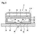
- FIGS. 1 to 3 a rain sensor 2 according to the invention is shown in schematic representations.
- the same parts in the figures are basically provided with the same reference numerals and will not be explained several times.
- the rain sensor 2 essentially comprises an upper part 4 with a housing cover 6 (see FIG. 1) and a support plate 20 (cf., FIG. 2) onto which the upper part 4 can be placed and latched.
- the rain sensor 2 built together is illustrated with reference to FIG.
- a circuit board 10 is fixed, on which a transmitter 12 and a receiver 14 is arranged.
- the transmitter 12 may in particular be an LED.
- the receiver 14 may be a photodiode or the like.
- the wavelength ranges of transmitter 12 and receiver 14 are suitably coordinated so that the transmitter 12 radiates a relatively narrow wavelength range and the receiver 14 is substantially sensitive only for this wavelength range.
- Emitter 12 and receiver 14 are located at opposite ends of the circuit board 10, so that a beam path 36 can be formed with obliquely aus fallendem and obliquely incident light.
- the entrance and exit angles are the same and can be within a reasonable range of approximately 45 degrees.
- a light guide carrier 8 is arranged, which is provided with lenses 16.
- a lens 16 is arranged, which provides for beam focusing.
- the printed circuit board 10 preferably has a circuit with the required transmitting and evaluation and is connected via a plug (not shown) to the vehicle electrical system.
- the housing cover 6 has a cylindrical or cuboid contour with pulled down side parts 18. These serve for connection to lateral locking webs 22 of the support plate 20, which forms the lower part of the rain sensor 2.
- the support plate 20 preferably has a round or rectangular contour, which is the contour of the housing cover 6 is adapted and is applied with a bottom on a glass plate 34.
- the connection to the glass pane 34, which is preferably a windshield of a motor vehicle, is expediently carried out via an adhesive layer 32. The rain sensor 2 is thus applied flush and firmly on the surface of the glass pane 34.
- connection to the housing cover 6 via laterally from the vertically pulled-up locking webs 22 projecting locking lugs 24 which engage in corresponding recesses (not shown) on the inner sides of the side members 18 and in this way for a solid, but if necessary releasable connection of the upper part 4 can provide with the lower part of the support plate 20.
- the support plate 20 is further provided with a transparent structural component 26 for coupling and uncoupling the light rays from the rain sensor 2 and into the glass pane 34.
- a water droplet 40 is indicated, which ensures a change in the refractive ratios at the interface to the air. This changed refraction of light results in a variable signal attenuation of the light component detected by the receiver and is a measure of the wetting of the glass plate 34 with a moist precipitate.
- the structural component 26 of the carrier plate 20 has a first extraneous light barrier 28, which covers a light emitted between a coupling point for emitted by the transmitter 12 light and a coupling point for detected by the receiver 14 light inner region and for the transmitter 12 and Receiver 14 is processed light impermeable.
- the first extraneous light barrier 28 can ensure that, in the light incident on the receiver 14, as far as possible all ambient light components remain filtered out, as a result of which the reliability of the signals supplied by the rain sensor 2 can be increased.
- a second extraneous light barrier 30 is located on the underside of the support plate 20 in an area outside of the input and output coupling and thus in an area around the first extraneous light barrier 28.
- the second extraneous light barrier 30 may be made of the same material as the first extraneous light barrier 28.
- a second aluminum light barrier is particularly suitable also an aluminum sheet o. The like., which is provided with the required openings.
- the first extraneous light barrier 28 can be realized, for example, with a lacquer layer or with a plastic layer, which are preferably applied to the structural component 26 by means of a so-called IMD process (in-mold decoration process).
- IMD process in-mold decoration process
- the paint or plastic layer is already introduced into the injection mold before it is filled under pressure with plastic.
- the finished plastic component is then the thus firmly connected paint or plastic layer.
- the plastic layer may in particular have a two-layered construction with a first layer of a plastic mask and a second layer of an optically active plastic film.
- the aluminum sheet of the second extraneous light barrier 30 may optionally be glued to the support plate 20 or be connected by means of the injection molding process with this.
- the first extraneous light barrier 28 may also consist of a metal or ceramic mask whose openings each define the beam path within the measuring path between transmitter 12 and receiver 14. Also suitable for the production of a firm connection between the dimensionally stable mask made of metal or ceramic and the transparent structural component 26 is in particular the IMD method.
- the extraneous light barriers 28, 30 can also be produced by so-called.
- Injection molding in the injection molding process Injection molding in the injection molding process.
- a metal mask can also be produced by means of a die-casting process, which can be combined with a subsequent injection molding process for producing the structural component made of plastic.
- the plastic or metal mask of the first and second extraneous light barrier may preferably have punched openings at the input and output points of the beam path 36, whereby the light exit and the light entry areas are defined.
- the color film may in particular have a filtering effect for extraneous light with a different wavelength range. In this way, the signal quality of the rain sensor 2 can be further improved.
- the first extraneous light barrier 28 may optionally be applied to the inside of the carrier plate 20 facing the transmitter 12 and receiver 14. This variant is illustrated in FIGS. 2 and 3. However, it can also be attached to the glass pane 34 facing bottom.
- the second extraneous light barrier 30 can also be applied externally or internally.
Landscapes
- Engineering & Computer Science (AREA)
- Automation & Control Theory (AREA)
- Mechanical Engineering (AREA)
- Physics & Mathematics (AREA)
- Health & Medical Sciences (AREA)
- Life Sciences & Earth Sciences (AREA)
- Chemical & Material Sciences (AREA)
- Analytical Chemistry (AREA)
- Biochemistry (AREA)
- General Health & Medical Sciences (AREA)
- General Physics & Mathematics (AREA)
- Immunology (AREA)
- Pathology (AREA)
- Investigating Or Analysing Materials By Optical Means (AREA)
Claims (21)
- Capteur de pluie notamment pour un véhicule automobile, comportant un chemin de mesure ayant au moins un émetteur et au moins un récepteur d'ondes électromagnétiques, chemin dans lequel se trouve un pare-brise qui influence le développement des ondes entre l'émetteur et le récepteur de façon que lorsque se développe un dépôt sur le pare-brise, en particulier le mouillage du pare-brise par un dépôt humide, le signal de sortie détecté par le réflecteur change et des structures sont prévues qui ont des propriétés de regroupement de faisceaux pour coupler et découpler les ondes électromagnétiques et sur lesquelles est prévue une barrière contre la lumière étrangère (28, 30),
caractérisé en ce que
la barrière contre la lumière étrangère (28, 30) se compose principalement d'une couche de matière plastique, de métal ou de matière céramique, reliée par injection aux structures, cette couche étant transparente aux ondes électromagnétiques seulement dans les zones du chemin de mesure. - Capteur de pluie selon la revendication 1,
caractérisé en ce que
les structures pour coupler et découpler les ondes électromagnétiques sont formées d'un composant de structure intégrée (26). - Capteur de pluie selon la revendication 1 ou 2,
caractérisé en ce que
la barrière contre la lumière étrangère (26, 28) est réalisée par une couche de matière plastique formant un masque avec des ouvertures, notamment des ouvertures matricées. - Capteur de pluie selon la revendication 3,
caractérisé en ce que
la couche de matière plastique est un film de matière plastique à plusieurs couches formées d'une superposition de films constituant un masque et de films de matière plastique à activité optique. - Capteur de pluie selon la revendication 3 ou 4,
caractérisé en ce que
la couche de matière plastique est un masque en matière plastique injectée comportant des ouvertures. - Capteur de pluie selon la revendication 4,
caractérisé en ce que
le film formant un masque non transparent aux ondes électromagnétiques comporte des ouvertures dans les zones de sortie de la lumière et des zones d'entrée de la lumière, notamment des ouvertures matricées. - Capteur de pluie selon l'une des revendications 4 et 6,
caractérisé en ce que
le film de matière plastique optiquement actif est un film teinté. - Capteur de pluie selon la revendication 7,
caractérisé en ce que
le film teinté a un effet de filtre. - Capteur de pluie selon la revendication 1 ou 2,
caractérisé en ce que
la barrière contre la lumière étrangère (28, 30) prévue sur les structures pour coupler et découpler les ondes électromagnétiques ou sur un composant de structure (26) se compose principalement d'une couche de vernis qui ne comporte des dégagements que dans les zones des chemins de mesure transparentes aux ondes électromagnétiques. - Capteur de pluie selon la revendication 1 ou 2,
caractérisé en ce que
la barrière contre la lumière étrangère (28, 30) prévue sur les structures pour coupler et découpler les ondes électromagnétiques ou sur le composant de structure (26) est formée principalement d'une couche métallique qui est transparente aux ondes électromagnétiques que dans les zones du chemin de mesure. - Capteur de pluie selon la revendication 10,
caractérisé en ce que
la couche métallique est un masque de métal avec des ouvertures, notamment des ouvertures découpées à la matrice. - Capteur de pluie selon la revendication 1 ou 2,
caractérisé en ce que
la barrière contre la lumière étrangère (28, 30) prévue sur les structures pour coupler et découpler les ondes électromagnétiques ou sur le composant de structure (26) se compose principalement d'une couche en céramique qui n'est transparente aux ondes électromagnétiques que dans les zones du chemin de mesure. - Capteur de pluie selon la revendication 12,
caractérisé en ce que
la couche en céramique est un masque en céramique muni d'orifices réalisés dans le masque. - Capteur de pluie selon l'une des revendications précédentes,
caractérisé en ce que
la zone de sortie de lumière et la zone d'entrée de lumière est définie par les ouvertures de la couche de matière plastique, de la couche de métal ou de la couche de céramique. - Capteur de pluie selon l'une des revendications précédentes,
caractérisé en ce que
la barrière contre la lumière étrangère (28, 30) est appliquée sur le côté des structures tourné vers l'émetteur (12) et le récepteur (14) pour coupler et découpler les ondes électromagnétiques ou sur le composant de structure (26). - Capteur de pluie selon l'une des revendications 1 à 14,
caractérisé en ce que
la barrière contre la lumière étrangère (28, 30) est appliquée sur le côté des structures non tourné vers l'émetteur (12) et le récepteur (14) pour coupler et découpler les ondes électromagnétiques ou du composant de structure (26). - Procédé de réalisation d'une barrière contre la lumière étrangère pour un capteur de pluie comportant un chemin de mesure formé d'au moins un émetteur et d'au moins un récepteur d'ondes électromagnétiques, chemin dans lequel se trouve le pare-brise qui influence le développement des ondes entre l'émetteur et le récepteur de façon que lorsque se développe un dépôt sur le pare-brise, notamment lorsqu'il est mouillé par un dépôt humide, le signal de sortie détecté par le récepteur change et les structures pour coupler et découpler des ondes électromagnétiques ayant des caractéristiques de regroupement du faisceau, les structures étant munies d'une barrière contre la lumière étrangère (28, 30) en dehors du chemin de mesure qui n'est pas transparente aux ondes électromagnétiques,
caractérisé en ce que
la barrière contre la lumière étrangère (28, 30) est appliquée par injection sur les structures pour coupler et découpler les ondes électromagnétiques. - Procédé selon la revendication 17,
caractérisé en ce que
la barrière contre la lumière étrangère (28, 30) est appliquée par un procédé d'injection en plusieurs phases. - Procédé selon la revendication 17 ou la revendication 18,
caractérisé en ce que
la barrière contre la lumière étrangère (28, 30) est appliquée par un procédé (IMD). - Procédé selon la revendication 19,
caractérisé en ce que
la barrière contre la lumière étrangère (28, 30) est un masque en matière plastique, en métal ou en céramique que l'on place dans le moule avant de le remplir avec de la matière thermoplastique transparente. - Procédé selon la revendication 20,
caractérisé en ce que
la barrière contre la lumière étrangère (28, 30) forme pendant l'injection une liaison solide et définitive avec les structures pour coupler et découpler les ondes électromagnétiques.
Applications Claiming Priority (2)
| Application Number | Priority Date | Filing Date | Title |
|---|---|---|---|
| DE10261102 | 2002-12-20 | ||
| DE10261102A DE10261102A1 (de) | 2002-12-20 | 2002-12-20 | Regensensor, insbesondere für ein Kraftfahrzeug und Verfahren zu dessen Herstellung |
Publications (3)
| Publication Number | Publication Date |
|---|---|
| EP1431142A2 EP1431142A2 (fr) | 2004-06-23 |
| EP1431142A3 EP1431142A3 (fr) | 2005-03-09 |
| EP1431142B1 true EP1431142B1 (fr) | 2006-09-13 |
Family
ID=32336603
Family Applications (1)
| Application Number | Title | Priority Date | Filing Date |
|---|---|---|---|
| EP03012391A Expired - Lifetime EP1431142B1 (fr) | 2002-12-20 | 2003-05-30 | Capteur de pluie, en particulier pour un véhicule et méthode pour sa fabrication |
Country Status (3)
| Country | Link |
|---|---|
| EP (1) | EP1431142B1 (fr) |
| DE (2) | DE10261102A1 (fr) |
| ES (1) | ES2272844T3 (fr) |
Families Citing this family (8)
| Publication number | Priority date | Publication date | Assignee | Title |
|---|---|---|---|---|
| DE102004033734A1 (de) * | 2004-07-13 | 2006-02-02 | Leopold Kostal Gmbh & Co. Kg | Optoelektronische Sensoreinrichtung für ein Kraftfahrzeug |
| DE102004038422B3 (de) * | 2004-07-30 | 2006-01-12 | Schefenacker Vision Systems Germany Gmbh | Sensoreinrichtung, Verwendung einer Sensoreinrichtung sowie Fahrzeugleuchte |
| DE102008033204A1 (de) | 2008-07-15 | 2010-02-04 | Trw Automotive Electronics & Components Gmbh | Optischer Sensor |
| US8873062B2 (en) * | 2012-08-09 | 2014-10-28 | Jeffrey Scott Adler | Reflective material sensor |
| DE102014218249A1 (de) * | 2014-09-11 | 2015-12-17 | Conti Temic Microelectronic Gmbh | Vorrichtung zur befestigung eines optischen sensors an der innenseite einer fahrzeugscheibe |
| US10421344B2 (en) * | 2017-05-16 | 2019-09-24 | Ford Global Technologies, Llc | Windshield barrier |
| DE102017122444B4 (de) | 2017-09-27 | 2022-06-15 | Bcs Automotive Interface Solutions Gmbh | Linsenplatte, Regensensor und Lichtsensor |
| DE102024132548A1 (de) * | 2024-11-07 | 2026-05-07 | Elmos Semiconductor Se | Dämpfung eines optischen Pfads zu einem optischen Empfänger mittels eines optischen Elements mit Leiterplatte |
Family Cites Families (9)
| Publication number | Priority date | Publication date | Assignee | Title |
|---|---|---|---|---|
| DE19643465C2 (de) | 1996-10-22 | 1999-08-05 | Bosch Gmbh Robert | Steuervorrichtung für einen optischen Sensor, insbesondere einen Regensensor |
| JPH11157417A (ja) * | 1997-11-26 | 1999-06-15 | Nippon Sheet Glass Co Ltd | 付着物検出センサを備えた透明基板 |
| DE19839273A1 (de) | 1998-03-17 | 1999-09-23 | Bosch Gmbh Robert | Optischer Sensor |
| DE19827541A1 (de) | 1998-03-19 | 1999-09-23 | Bosch Gmbh Robert | Scheibenwischvorrichtung |
| DE19846969A1 (de) | 1998-04-08 | 1999-10-14 | Bosch Gmbh Robert | Regensensor |
| DE19846968A1 (de) | 1998-04-08 | 1999-10-14 | Bosch Gmbh Robert | Regensensor |
| DE19955423A1 (de) * | 1999-11-18 | 2001-05-31 | Hella Kg Hueck & Co | Sensoreinrichtung und Verfahren zur Herstellung einer Sensoreinrichtung |
| DE10041776A1 (de) | 2000-08-25 | 2002-03-07 | Bosch Gmbh Robert | Regensensor, insbesondere für ein Kraftfahrzeug |
| DE10060964A1 (de) | 2000-12-06 | 2002-06-13 | Bosch Gmbh Robert | Regensensor, insbesondere für ein Kraftfahrzeug |
-
2002
- 2002-12-20 DE DE10261102A patent/DE10261102A1/de not_active Withdrawn
-
2003
- 2003-05-30 EP EP03012391A patent/EP1431142B1/fr not_active Expired - Lifetime
- 2003-05-30 ES ES03012391T patent/ES2272844T3/es not_active Expired - Lifetime
- 2003-05-30 DE DE50305019T patent/DE50305019D1/de not_active Expired - Lifetime
Also Published As
| Publication number | Publication date |
|---|---|
| EP1431142A2 (fr) | 2004-06-23 |
| DE10261102A1 (de) | 2004-07-01 |
| EP1431142A3 (fr) | 2005-03-09 |
| ES2272844T3 (es) | 2007-05-01 |
| DE50305019D1 (de) | 2006-10-26 |
Similar Documents
| Publication | Publication Date | Title |
|---|---|---|
| EP2000373B1 (fr) | Dispositif de capteur optique destiné à détecter la présence d'humidité et procédé de fabrication d'un tel dispositif | |
| EP1101673B1 (fr) | Capteur et méthode de fabrication d'un capteur | |
| EP1068112B1 (fr) | Detecteur de pluie | |
| EP1289796A1 (fr) | Unite de detection photosensible, notamment pour la commutation automatique de dispositifs d'eclairage | |
| DE4019066A1 (de) | Vorrichtung zum optischen erfassen eines belags | |
| EP1072383A1 (fr) | Article de matière plastique moulé par injection à plusieurs composants comprenant une fonction d'affichage optique | |
| DE102023106330B3 (de) | Sensormodul zur Anbringung an einem Flächenbauteil eines Kraftfahrzeuges und Dachmodul zur Bildung eines Fahrzeugdaches an einem Kraftfahrzeug | |
| WO2019129487A1 (fr) | Galerie de toit pour un véhicule à moteur | |
| DE202020101446U1 (de) | Abdeckung für Fahrzeugsensormodule | |
| EP1431142A2 (fr) | Capteur de pluie, en particulier pour un véhicule et méthode pour sa fabrication | |
| EP1784324B1 (fr) | Systeme de capteur optoelectronique destine a un vehicule | |
| EP1045779B1 (fr) | Detecteur optique | |
| DE19846969A1 (de) | Regensensor | |
| EP1578648A1 (fr) | Detecteur de pluie, destine notamment a un vehicule automobile | |
| WO2003026937A1 (fr) | Capteur holographique, notamment pour la detection d'humidite sur une vitre d'un vehicule automobile | |
| EP2259953B1 (fr) | Dispositif de détermination des propriétés de réflexion d'une interface avec atténuation améliorée des lumières parasites | |
| DE102019128013A1 (de) | Fahrzeugbauteil zur Integration eines Umgebungserfassungssensors in ein Fahrzeug | |
| DE102014014294A1 (de) | Stoßfänger für ein Kraftfahrzeug und Kraftfahrzeug | |
| EP1908652B1 (fr) | Détecteur de pluie | |
| EP1431145B1 (fr) | Capteur de pluie, en particulier pour un véhicule automobile | |
| WO2004060729A1 (fr) | Detecteur de pluie, destine notamment a un vehicule automobile | |
| DE10034555A1 (de) | Lichtempfindliche Sensoreinheit, insbesondere zum automatischen Schalten von Beleuchtungseinrichtungen | |
| DE102008054638A1 (de) | Lichtleiter | |
| DE102004030777B4 (de) | Gehäuse für einen optischen Sensor | |
| DE102005009424A1 (de) | Optischer Sensor mit optimierter Sensitivität |
Legal Events
| Date | Code | Title | Description |
|---|---|---|---|
| PUAI | Public reference made under article 153(3) epc to a published international application that has entered the european phase |
Free format text: ORIGINAL CODE: 0009012 |
|
| AK | Designated contracting states |
Kind code of ref document: A2 Designated state(s): AT BE BG CH CY CZ DE DK EE ES FI FR GB GR HU IE IT LI LU MC NL PT RO SE SI SK TR |
|
| AX | Request for extension of the european patent |
Extension state: AL LT LV MK |
|
| PUAL | Search report despatched |
Free format text: ORIGINAL CODE: 0009013 |
|
| AK | Designated contracting states |
Kind code of ref document: A3 Designated state(s): AT BE BG CH CY CZ DE DK EE ES FI FR GB GR HU IE IT LI LU MC NL PT RO SE SI SK TR |
|
| AX | Request for extension of the european patent |
Extension state: AL LT LV MK |
|
| 17P | Request for examination filed |
Effective date: 20050909 |
|
| AKX | Designation fees paid |
Designated state(s): DE ES FR GB IT |
|
| GRAP | Despatch of communication of intention to grant a patent |
Free format text: ORIGINAL CODE: EPIDOSNIGR1 |
|
| GRAS | Grant fee paid |
Free format text: ORIGINAL CODE: EPIDOSNIGR3 |
|
| GRAA | (expected) grant |
Free format text: ORIGINAL CODE: 0009210 |
|
| AK | Designated contracting states |
Kind code of ref document: B1 Designated state(s): DE ES FR GB IT |
|
| PG25 | Lapsed in a contracting state [announced via postgrant information from national office to epo] |
Ref country code: IT Free format text: LAPSE BECAUSE OF FAILURE TO SUBMIT A TRANSLATION OF THE DESCRIPTION OR TO PAY THE FEE WITHIN THE PRESCRIBED TIME-LIMIT;WARNING: LAPSES OF ITALIAN PATENTS WITH EFFECTIVE DATE BEFORE 2007 MAY HAVE OCCURRED AT ANY TIME BEFORE 2007. THE CORRECT EFFECTIVE DATE MAY BE DIFFERENT FROM THE ONE RECORDED. Effective date: 20060913 |
|
| REG | Reference to a national code |
Ref country code: GB Ref legal event code: FG4D Free format text: NOT ENGLISH |
|
| REF | Corresponds to: |
Ref document number: 50305019 Country of ref document: DE Date of ref document: 20061026 Kind code of ref document: P |
|
| GBT | Gb: translation of ep patent filed (gb section 77(6)(a)/1977) |
Effective date: 20070102 |
|
| ET | Fr: translation filed | ||
| REG | Reference to a national code |
Ref country code: ES Ref legal event code: FG2A Ref document number: 2272844 Country of ref document: ES Kind code of ref document: T3 |
|
| PLBE | No opposition filed within time limit |
Free format text: ORIGINAL CODE: 0009261 |
|
| STAA | Information on the status of an ep patent application or granted ep patent |
Free format text: STATUS: NO OPPOSITION FILED WITHIN TIME LIMIT |
|
| 26N | No opposition filed |
Effective date: 20070614 |
|
| PGFP | Annual fee paid to national office [announced via postgrant information from national office to epo] |
Ref country code: GB Payment date: 20100324 Year of fee payment: 8 |
|
| PGFP | Annual fee paid to national office [announced via postgrant information from national office to epo] |
Ref country code: ES Payment date: 20100520 Year of fee payment: 8 Ref country code: FR Payment date: 20100608 Year of fee payment: 8 |
|
| PGFP | Annual fee paid to national office [announced via postgrant information from national office to epo] |
Ref country code: IT Payment date: 20100527 Year of fee payment: 8 |
|
| REG | Reference to a national code |
Ref country code: DE Ref legal event code: R084 Ref document number: 50305019 Country of ref document: DE |
|
| GBPC | Gb: european patent ceased through non-payment of renewal fee |
Effective date: 20110530 |
|
| REG | Reference to a national code |
Ref country code: FR Ref legal event code: ST Effective date: 20120131 |
|
| PG25 | Lapsed in a contracting state [announced via postgrant information from national office to epo] |
Ref country code: IT Free format text: LAPSE BECAUSE OF NON-PAYMENT OF DUE FEES Effective date: 20110530 |
|
| PG25 | Lapsed in a contracting state [announced via postgrant information from national office to epo] |
Ref country code: FR Free format text: LAPSE BECAUSE OF NON-PAYMENT OF DUE FEES Effective date: 20110531 |
|
| PG25 | Lapsed in a contracting state [announced via postgrant information from national office to epo] |
Ref country code: GB Free format text: LAPSE BECAUSE OF NON-PAYMENT OF DUE FEES Effective date: 20110530 |
|
| REG | Reference to a national code |
Ref country code: ES Ref legal event code: FD2A Effective date: 20121207 |
|
| PG25 | Lapsed in a contracting state [announced via postgrant information from national office to epo] |
Ref country code: ES Free format text: LAPSE BECAUSE OF NON-PAYMENT OF DUE FEES Effective date: 20110531 |
|
| PGFP | Annual fee paid to national office [announced via postgrant information from national office to epo] |
Ref country code: DE Payment date: 20160726 Year of fee payment: 14 |
|
| REG | Reference to a national code |
Ref country code: DE Ref legal event code: R119 Ref document number: 50305019 Country of ref document: DE |
|
| PG25 | Lapsed in a contracting state [announced via postgrant information from national office to epo] |
Ref country code: DE Free format text: LAPSE BECAUSE OF NON-PAYMENT OF DUE FEES Effective date: 20171201 |