EP1431183A1 - Outil de cerclage - Google Patents
Outil de cerclage Download PDFInfo
- Publication number
- EP1431183A1 EP1431183A1 EP04004426A EP04004426A EP1431183A1 EP 1431183 A1 EP1431183 A1 EP 1431183A1 EP 04004426 A EP04004426 A EP 04004426A EP 04004426 A EP04004426 A EP 04004426A EP 1431183 A1 EP1431183 A1 EP 1431183A1
- Authority
- EP
- European Patent Office
- Prior art keywords
- strapping
- shaft
- strap
- guide
- movable
- Prior art date
- Legal status (The legal status is an assumption and is not a legal conclusion. Google has not performed a legal analysis and makes no representation as to the accuracy of the status listed.)
- Withdrawn
Links
Images




Classifications
-
- B—PERFORMING OPERATIONS; TRANSPORTING
- B25—HAND TOOLS; PORTABLE POWER-DRIVEN TOOLS; MANIPULATORS
- B25B—TOOLS OR BENCH DEVICES NOT OTHERWISE PROVIDED FOR, FOR FASTENING, CONNECTING, DISENGAGING, OR HOLDING
- B25B33/00—Hand tools not covered by any other group in this subclass
-
- B—PERFORMING OPERATIONS; TRANSPORTING
- B65—CONVEYING; PACKING; STORING; HANDLING THIN OR FILAMENTARY MATERIAL
- B65B—MACHINES, APPARATUS OR DEVICES FOR, OR METHODS OF, PACKAGING ARTICLES OR MATERIALS; UNPACKING
- B65B13/00—Bundling articles
- B65B13/18—Details of, or auxiliary devices used in, bundling machines or bundling tools
- B65B13/24—Securing ends of binding material
- B65B13/30—Securing ends of binding material by deforming the overlapping ends of the strip or band
- B65B13/305—Hand tools
Definitions
- the present invention pertains to an improved strapping tool. More particularly, the present invention pertains to a strapping tool that accommodates strapping material of varying widths and thickness, and facilitates operation in more than one orientation.
- Strapping machines or strappers are well known in the art. The machines are used to strap together articles, e.g., a load, with strapping material. Strapping material is offered in a variety of sizes and materials and is generally stored on a roll. Conventional strapping materials include plastic and metals, such as steel. Steel strapping is typically coated with, for example paint, to inhibit corrosion.
- a free end of strapping material is passed around the load until there is an overlap between the free end and the strapping material still connected to the roll.
- the overlapping portion of strapping material is placed between jaws of a strapping machine and the free end of the strapping material is fixed in place by a gripper portion of the machine.
- the material is generally tightened or tensioned around the articles to a desired tension. This is accomplished by operating a feed wheel to pull back or tension the strapping material.
- a typical strapping machine includes sealing heads for sealing the free end of the strapping material onto itself, around the load.
- a handle is rotated which applies a force to cause a punch or sealing head to engage and press down against the strap to seal the strap to itself.
- the strapping material still connected to the roll is cut by a cutter, which is a portion of the strapper. This completes one strapping operation.
- a strapping machine is shown in US-A-5526852.
- the sealing head and the cutter are carried by a jaw assembly within the strapper.
- the jaw assembly includes a stationary or fixed sealing head, a movable sealing head and the cutter.
- the cutter moves with the movable sealing head into and out of engagement with the strap material to form the seal and cut the strap from the roll or supply.
- the movable portion of the jaw is actuated by rotation of an actuator handle. The handle rotates about a shaft that is positioned within the strapper body.
- straps are typically available having standard widths and thicknesses (i.e., gauges), there are tolerances within which the strap may be supplied. This is particularly the case with respect to the strap gauge. Strap is typically available in standard thicknesses of 1 ⁇ 2 inch, 5/8 inch and 3 ⁇ 4 inch, (12mm, 15mm and 18mm).
- the shaft on which the actuator handle is positioned is eccentrically formed.
- the portion of the handle that is positioned with the strapper body has one axis of rotation and the portion on which the jaw assembly is mounted has different axis of rotation. This permits adjusting the distance that the movable sealing head moves relative to the fixed sealing head, and thus permits adjusting the gap between the sealing heads when the heads are fully engaged.
- a hexagonal key extends from an end of the shaft.
- a plate having a key-way with a mating hexagonal opening is fitted over the key and is secured in place to the strapper body by a fastener that is inserted though a notched opening in the plate. The plate can be rotated such that the fastener rides through the notched opening to rotate the shaft for adjusting the shaft position (and thus the height of the movable sealing head).
- one strapper uses a simple, removable stop plate against which the strap rests when it is fully inserted into the jaw assembly. In one position, the plate is configured to accommodate one width of strap, and when removed, the strapper accommodates another size of strap. Thus, only two of the three "standard" widths are accommodate by any one strapper without major reconfiguration and changes to the tool.
- the strapper may be operated with the jaw residing horizontally, vertically or even at an incline between the horizontal and vertical.
- the orientation and position of the actuating handle can be different throughout use at any given site or location.
- a strapper machine that can be readily adjusted to accommodate strap material of varying widths and thicknesses.
- a strapper accommodates strap material of varying thicknesses, such as when rolls of material are changed out, with minimal effort. More desirable, such a strapper further permits maintenance on the strapper head or jaw while maintaining a predetermined setting for the strap thickness.
- such a strapper can accommodate any of the three standard strap widths with minimal adjustment. Desirable, such a strap width adjustment is carried out by movement of parts within and part of the strap width setting assembly. Moreover, such a strapper further accommodates operation an a variety of orientations and positions so as to reduce operator fatigue and to improve leverage in operation of the actuator handle.
- a strapping machine forms a seal between two portions of strapping material and cuts an upper layer of the strapping material without impinging a lower layer of the strapping material.
- the strapping machine typically includes a strapping machine body having first and second shaft apertures formed therein.
- the body further includes first and second fastener apertures formed in the body adjacent one of the shaft apertures.
- first and second shaft sections integral with one another defining primary and secondary axes of rotation.
- the first shaft section defines two sections, each defining the primary axis of rotation.
- the second shaft section is eccentric relative to the first shaft section, and defines the secondary axis of rotation.
- the axes are spaced from and parallel to one another.
- the shaft is positioned in the body with the first shaft sections in the shaft apertures for rotation therein.
- the shaft sections can have equal or different diameters with different axes of rotation.
- a key extends from an end of the first shaft section.
- the machine typically includes a fixed support and a movable support.
- the movable support includes a cutter mounted thereto and is movable away from and toward the fixed support to form the seal and cut the upper layer of strapping material.
- the movable support is movable toward the fixed support to a define desired clearance therebetween.
- An actuating lever is rotatable about the eccentric, second shaft section.
- the actuating lever is operably connected to the movable support for moving the movable support toward and away from the fixed support.
- the actuating lever includes a pivot portion and a reversible handle.
- the handle has a straight segment and an angled segment.
- the reversible handle is removably connected to the pivot portion and can be secured to the pivot portion in a first orientation in which the angled segment extends in a first direction and a second orientation opposite the first orientation.
- the handle can be secured to the pivot portion by fasteners.
- the strapping machine can further include a variable strap width accommodating assembly.
- the variable width assembly includes outside and inside guides to secure and hold the strapping material between the fixed and movable supports during the sealing and cutting operation.
- the outside guide includes first and second guide elements pivotally connected to one another.
- the outside guide is removably connected to the strapping machine body.
- the first and second guide elements have different thicknesses relative to a plane defined generally by the strapping material between the fixed and movable supports.
- the outside guide elements are configured to pivot so that one is positioned in a depending orientation relative to the other.
- An inside guide is mounted to the strapping machine body intersecting the strapping material plane.
- the depending outside guide element guide is moveable into the strapping material plane to abut the strapping material and position the strapping material between the inside and outside guides when the movable support is moved toward the fixed support for forming the seal.
- the outside guide first and second elements are pivotally mounted to one another by a pivot pin.
- the entire outside guide is mounted to the strapping machine body by the pivot pin.
- the non-depending outside guide element is positioned in a longitudinal orientation relative to the depending guide element.
- the longitudinally oriented element is further mounted to the strapping machine body by a pin connecting the longitudinal guide element to the strapping machine body to secure the outside guide to the body.
- the inside guide defines first and second guide edges and is connected to the strapping machine body at a point of connection.
- the point of connection is a first distance from the first guide edge and a second distance from the second guide edge, different from the first distance.
- Apertures are formed in the inside guide and the strapping machine body at the point of connection.
- a fastener secures the guide to the strapping machine body.
- the inside and outside guides are independently positionable on the strapping machine body.
- the machine accommodates at least three different strapping material widths.
- the invention may be used in a variety of strapping machines or strapping tools (also referred to as strappers) such as the exemplary strapper 2 illustrated in FIG. 1.
- the illustrated strapper 2 includes a strapping machine body 4, a gripper (not shown), feed wheel 6 and accompanying feed lever 8.
- the illustrated strapper 2 further includes a cutter 10 (FIG. 2) and accompanying actuating lever 12, which is configured to rotate about an eccentric shaft 14.
- a jaw assembly 16 is operably connected to the shaft 14 and actuating lever 12, as will be described below.
- the jaw assembly 16 includes movable and fixed supports 18, 20, respectively. Sealing elements 22 are carried by the supports 18, 20.
- Those skilled in the art will recognize and appreciate the various strapping machines that may include different embodiments of grippers, feed wheels and/or accompanying levers and cutters, or other structures used to grip a strap, tension a strap around a load and cut the strap.
- a first end of strapping material S which can be stored on a roll, is passed around a load L and fed into the jaw assembly 16, between the movable and fixed supports 18,20 and gripped by the gripper. This results in an overlap of strapping material S so the first end, which is gripped by the gripper, forms a lower layer of strapping material 24.
- the feed wheel 6 and the accompanying feed lever 8 are then operated to tighten the strap around the load L.
- the strap S which defines a plane, generally indicated P in FIG. 1, is then sealed to itself and cut by the cutter 10.
- a seal is formed in the strapping material S, between the upper layer 26 of the strap and the lower layer 24 by rotating the actuating lever 12, which will cause the movable support 18 to move downwardly toward the fixed support 20 with the strap S therebetween, as shown in FIG. 1.
- this causes the sealing elements 22, which are attached to the movable support 18, to seal the upper layer of strap material 26 into the lower layer of strap material 24.
- This also causes the cutter 10 to engage and cut the upper layer of strapping material 26 from the roll.
- the cutter 10 is mounted to the movable support 18, which, in turn is operably connected to the actuating lever 12, by a connector 28.
- the connector 28 includes a pin 30 formed on the actuating handle 12, spaced from the handle's axis of rotation, and a hook 32 formed on the movable support 18. The hook 32 and the pin 30 cooperate with one another such that rotation of the handle 12 (as seen in FIG. 2) lifts the movable support 18 upward, away from the fixed support 20.
- the actuating lever 12 rotates about the eccentric shaft 14, as will be described below.
- connector 28 configurations that provide for translation of rotational movement into linear or near linear movement will be recognized by those skilled in the art, such as variations of the illustrated, exemplary pin and hook configuration.
- the connector 28 includes a flat surface 33, contiguous with a curved or arcuate camming surface 35.
- the camming surface 35 contacts a bearing surface 37 of the movable support 18, urging the support 18 downwardly (to the fixed support 20), a distance that is equal to the radial distance d 35 from the camming surface 35 to the primary axis of rotation A 1 , described below.
- the initial height of the cutter 10 is adjusted to ensure that the cutter 10 does not impinge the lower layer of strapping material 24 during cutting operation. This is to reduce the potential for impinging the lower layer of strapping material 24 which can affect the integrity of the strap used to bind the load together.
- the cutter 10 height is adjusted by rotating the eccentric shaft 14. Because the cutter 10 is fixedly mounted to the movable support 18, rotating the eccentric shaft 14 varies the radial distance d 35 from the camming surface 35 to the primary axis of rotation A 1 .
- the shaft 14 operably connects the handle 12 to the strapper body 4 and the jaw assembly 16, including the cutter 10.
- the ends 34,36 of the eccentric shaft are positioned within shaft apertures 38,40 formed within the body 4 in a manner that allows for the shaft 14 to rotate, as shown in FIGS. 2-4.
- the illustrated eccentric shaft 14 is formed having three shaft sections 42,44, 46 that are integral with one another.
- the first shaft section 42 has a first end 48.
- the first and third or outer sections 42,46 have a common axis of rotation A 1 , which defines the first or primary axis of rotation.
- the second or central shaft section 44 is eccentric relative to the outer sections 42,46, and thus defines the second or secondary axis of rotation 2 that is parallel to and spaced from the primary axis A 1 .
- the outer shaft sections 42,46 are positioned and rotate within the strapper body 4, while the central shaft section 44 resides within the handle aperture, and provides a pivot, i.e., an axis of rotation A 2 , for the handle 12.
- a pivot i.e., an axis of rotation A 2
- the handle 12 rotates about the central section 44, the location of the handle 12 axis (the secondary axis A 2 ) moves or shifts relative to the body 4 and the fixed support 20 as the shaft 14 is rotated.
- the connector 28 (and thus the movable support 18) is operably connected to the handle 12.
- rotating the shaft 14 shifts the height of the connector 28 relative to the body 4 and support 18.
- rotation of the connector 28 (by rotating the handle 12) varies the radial distance d 35 that the movable support 18 (and attached cutter 10) are moved relative to the fixed support 20.
- rotating the shaft 14 shifts or varies the height of the cutter 10 relative to the fixed support 20.
- FIGS. 1-4 show the first and second ends 34,36 of the shaft 14 positioned in the first and second shaft apertures 38,40.
- the first end 34 shaft 14 has a shaped protrusion or key 60 formed thereon.
- a locking plate 62 is used to lock the position of the shaft 14 relative to the body 4.
- the plate 62 includes a key-way 64 formed as an aperture that corresponds to the key 60 on the shaft end 34 that cooperate with one another to lock the shaft into a desired position.
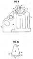
- the plate includes a second aperture formed as a notched opening as indicated at 66 or as a series of circular openings, as indicated at 69a-h in FIG. 4A, that cooperate with one of a plurality of fastener apertures 68, 70 formed within the strapper body 4.
- a fastener is inserted though the second aperture 66 and into one of the fastener apertures 68, 70 to lock the plate 62 and, consequently, the shaft 14 in a selected position.
- rotating the shaft shifts the position or height of the movable support 18 and thus the cutter 10 relative to the fixed support.
- locking the shaft 14 at a particular position locks the relative height of the cutter 10.
- the fastener arrangement in conjunction with the pair of apertures 68, 70 openings in the body 4 and the opening 66 slotted (or series of circular openings 69) in the plate 62 provides a wide range over which the shaft 14 can be locked into a desired position.
- the illustrated embodiment shows a threaded fastener inserted into and threadedly engaging the body 4, other configurations for this arrangement will be recognized by those skilled in the art.
- manual strapping machines are used to strap several groups of articles together at, for example, a remote location, site or as another example, at a warehouse facility.
- strapping machine disassembly may be required for service to, for example, dislodge an errant piece of strap that has become lodged in the tool.
- the strap supply need not be changed, and as such, it is desirable to maintain the height at which the cutter has been set.
- the plate 62 is generally kept in place and the eccentric shaft 14 is removed to perform the required maintenance.
- the key 60 is reinserted into the plate 62 to fit into or cooperate with the shaped aperture 64.
- the keys and apertures permit replacing the shaft in a position other than the original position prior to disassembly.
- a hexagonal key is fitted into a corresponding hexagonal aperture.
- the key 60 on the shaft as it fits into the plate aperture 64 permits replacement in only one orientation.
- the key 60 has a square shape having a corner removed to form an irregular, five-sided shape.
- the aperture 64 has a corresponding shape so that the key is received by the plate 62 in only one orientation.
- shaped keys and apertures can be used that permit the shaft to be replaced in only one position, such as, for example, any irregular shape including non-equilateral triangles, five cornered rectangles, or other non-symmetrical polygons.
- the slotted opening 66 (or series of circular openings 69) and the number of fastener apertures 68, 70 can be varied to increase the number of positions into which the key 62 can be locked into the plate to provide essentially a 180 degree range over which the shaft 14 can be locked into place.
- the variation in the placement, number and orientations of these cooperating openings will be recognized by those skilled in the art.
- a reversible actuating lever 12 permits strapping machine 2 operation in multiple orientations. Often times, due to awkwardly shaped loads, it may be easier to perform strapping operations by positioning the strapping machine 2 along a side of the load, rather than atop the load. Strapping along a side of the load or in other orientations, however, may be cumbersome, and may prevent use of maximum leverage to rotate the handle 12.
- the reversible actuating lever 12 allows a user to apply a force to the actuating lever in both horizontal and vertical orientations with greater ease.
- the reversible actuating lever 12 shown in FIG. 1 has a straight segment 76 and an angled segment 78.
- the straight segment 76 is removably connected to connector 28, which includes a circular portion 80 and a straight portion 82.
- the circular portion 80 is configured to pivot about the eccentric shaft portion 44.
- the straight segment of the connector 82 extends from the circular portion 80 and is removably connected to the straight segment of the actuating lever 76 by fasteners 84 inserted through apertures 86 formed therein.
- the fastener arrangement can include, for example, threaded bolts and the like. Alternately, the fastener can be of a clamp-like configuration that holds the two sections 76,82 together. Those skilled in the art will recognize the various other fastener arrangements that can be used for joining these sections of the lever 12.
- the reversible lever 12 of FIG. 2 has two positions P 1 , P 2 .
- a first position P 1 a first side of the lever 88 faces outward and a handle of the lever 90 points upward whereas a second side of the lever 92 faces outward and the handle 90 points downward in a second position P 2 .
- fasteners 84 that connect the straight segments of the actuating lever and connector 76, 82 to each other are removed to remove the actuating lever 12.
- the lever 12 is then "flipped" around and the fasteners 84 replaced.
- the reversible actuating lever and connector can be configured to have an infinite number of positions depending on the cross-sectional shape of the actuating lever and connector.
- the actuating lever a circular cross section with an 0-ring clamp configuration could permit adjustment in numerous positions.
- the present strapper 2 includes adjustable outside and inside guides 94,96 to accommodate these three different strap widths.
- the outside guide 94 is shown in a first position and includes a first guide element 98 pivotally connected to a second guide element 100 by a pin 102.
- the first and second guide elements can have differing lengths and thickness or have the same lengths and thickness in alternate embodiments.
- the inside guide 96 of FIG. 7 is a formed as a plate.
- the outside guide 94 shown in FIG. 2 shows the outside guide 94 connected to the strapping machine body 4 by two fasteners 104.
- a first aperture 106 is formed in the first guide element 98 and a second aperture 108 is formed in the second guide element 100.
- first and second holes 110,112 are formed in the strapping machine body 4.
- the first aperture and first hole 106,110 receive a fastener 104 and the second aperture and second hole 108,112 receive a second fastener 104 as shown in FIG. 2.
- FIG. 7 An inside guide 96 is shown in FIG. 7.
- the inside guide 96 is shown connected to a back end of the strapping machine body 114 at a point of connection aperture 116 formed within the inside guide 96 and a point of connection bore 118 formed within the back end 114 of the machine body 4 by a fastener 120.
- the back end 114 of the strapping machine body 4 a posterior side 122 of which is shown in FIG. 4, is illustrated with. other elements of the strapping machine 2 removed for ease of illustration.
- the inside guide 96 of FIG. 7 is a plate defined by a substantially rectangular shape and the point of connection aperture 116 is formed along a vertical axis V of the inside guide 96.
- the distance d 1 from the axis V and a first side 124 of the inside guide 96 is different from the distance d 2 between the axis V and a second side 126 of the inside guide 96, which is opposite the first side 122.
- the inside guide 96 can be defined by various shapes and be connected to the strapping machine body 4 at various locations and in various manners. To adjust the inside strapping guide 96, the user can loosen the fastener 120, and rotate the inside guide 96.
- the inside and outside guides 94,96 can accommodate straps of three different widths.
- the outside guide 94 may be in a first position and accommodate straps of two widths (A, B) when the inside guide 96 is in first and second positions.
- the outside guide 94 may be in a second position and accommodate straps of two different widths (C, D) when the inside guide 96 is in the first and second positions. It is, however, anticipated that two of the widths (e.g., widths B and D) are equal to one another, thus accommodating three different strap widths.
Landscapes
- Engineering & Computer Science (AREA)
- Mechanical Engineering (AREA)
- Basic Packing Technique (AREA)
- Polishing Bodies And Polishing Tools (AREA)
- Finger-Pressure Massage (AREA)
- Inorganic Insulating Materials (AREA)
- Surgical Instruments (AREA)
- Gripping On Spindles (AREA)
- Polyoxymethylene Polymers And Polymers With Carbon-To-Carbon Bonds (AREA)
- Moulds For Moulding Plastics Or The Like (AREA)
- Hand Tools For Fitting Together And Separating, Or Other Hand Tools (AREA)
- Portable Nailing Machines And Staplers (AREA)
Applications Claiming Priority (3)
| Application Number | Priority Date | Filing Date | Title |
|---|---|---|---|
| US09/866,256 US6772798B2 (en) | 2001-05-25 | 2001-05-25 | Strapping tool |
| US866256 | 2001-05-25 | ||
| EP02253330A EP1260440B1 (fr) | 2001-05-25 | 2002-05-13 | Outil de cerclage |
Related Parent Applications (1)
| Application Number | Title | Priority Date | Filing Date |
|---|---|---|---|
| EP02253330A Division EP1260440B1 (fr) | 2001-05-25 | 2002-05-13 | Outil de cerclage |
Publications (1)
| Publication Number | Publication Date |
|---|---|
| EP1431183A1 true EP1431183A1 (fr) | 2004-06-23 |
Family
ID=25347234
Family Applications (3)
| Application Number | Title | Priority Date | Filing Date |
|---|---|---|---|
| EP04004426A Withdrawn EP1431183A1 (fr) | 2001-05-25 | 2002-05-13 | Outil de cerclage |
| EP02253330A Expired - Lifetime EP1260440B1 (fr) | 2001-05-25 | 2002-05-13 | Outil de cerclage |
| EP04004425A Withdrawn EP1442983A1 (fr) | 2001-05-25 | 2002-05-13 | Outil de cerclage |
Family Applications After (2)
| Application Number | Title | Priority Date | Filing Date |
|---|---|---|---|
| EP02253330A Expired - Lifetime EP1260440B1 (fr) | 2001-05-25 | 2002-05-13 | Outil de cerclage |
| EP04004425A Withdrawn EP1442983A1 (fr) | 2001-05-25 | 2002-05-13 | Outil de cerclage |
Country Status (16)
| Country | Link |
|---|---|
| US (1) | US6772798B2 (fr) |
| EP (3) | EP1431183A1 (fr) |
| JP (1) | JP2003020008A (fr) |
| KR (1) | KR100777331B1 (fr) |
| CN (1) | CN1234568C (fr) |
| AT (1) | ATE281353T1 (fr) |
| AU (1) | AU763944B2 (fr) |
| BR (1) | BR0201873B1 (fr) |
| CA (1) | CA2382589C (fr) |
| DE (1) | DE60201774T2 (fr) |
| DK (1) | DK1260440T3 (fr) |
| ES (1) | ES2231654T3 (fr) |
| MX (1) | MXPA02005114A (fr) |
| NZ (2) | NZ519097A (fr) |
| PT (1) | PT1260440E (fr) |
| TW (1) | TW537994B (fr) |
Cited By (1)
| Publication number | Priority date | Publication date | Assignee | Title |
|---|---|---|---|---|
| CN109018489A (zh) * | 2018-08-21 | 2018-12-18 | 天津理工大学 | 一种钢管打包机压紧装置及其控制方法 |
Families Citing this family (24)
| Publication number | Priority date | Publication date | Assignee | Title |
|---|---|---|---|---|
| WO2000049593A1 (fr) * | 1999-02-19 | 2000-08-24 | Seiko Epson Corporation | Procede servant a fabriquer un panneau d'affichage et panneau d'affichage |
| US8708263B2 (en) | 2004-08-11 | 2014-04-29 | Roger T. Young | Hammer |
| TWM355900U (en) * | 2008-11-28 | 2009-05-01 | Yang Bey Ind Co Ltd | Positioning device for iron belt of packing device |
| CN102020025B (zh) * | 2009-09-11 | 2014-09-17 | 普利马克包装有限责任公司 | 封接工具附件 |
| CA2835857C (fr) | 2011-05-12 | 2021-02-23 | Genesis Iii, Inc. | Marteau |
| US9272799B2 (en) | 2011-10-04 | 2016-03-01 | Signode Industrial Group Llc | Sealing tool for strap |
| CN102437536B (zh) * | 2011-12-19 | 2014-04-23 | 郭文丁 | 张力无损伤绑线钳 |
| US9221567B2 (en) | 2012-01-25 | 2015-12-29 | Southern Bracing Systems Enterprises, Llc | Systems, methods, and devices for tensioning straps |
| US20130199382A1 (en) * | 2012-02-07 | 2013-08-08 | Band-It-Idex, Inc. | Band Tensioning Tool |
| JP6412003B2 (ja) | 2012-09-24 | 2018-10-24 | シグノード インターナショナル アイピー ホールディングス エルエルシー | 旋回可能なロッカーを有する結束装置 |
| US9630265B2 (en) * | 2013-06-28 | 2017-04-25 | Signode Industrial Group Llc | Powered two-stage strap cutter |
| US10308383B2 (en) * | 2014-07-21 | 2019-06-04 | Signode Industrial Group Llc | Electrically powered combination hand-held strapping tool |
| US10577137B2 (en) | 2015-12-09 | 2020-03-03 | Signode Industrial Group Llc | Electrically powered combination hand-held notch-type strapping tool |
| CN106143992B (zh) * | 2016-07-22 | 2020-02-14 | 温州汉德派克包装机械有限公司 | 一种打包机 |
| CN108438295B (zh) * | 2018-03-20 | 2023-07-07 | 杭州径缘新型墙体材料有限公司 | 一种用于砌块打包机的绕带装置及其绕带方法 |
| US11174051B2 (en) | 2019-02-15 | 2021-11-16 | Samuel, Son & Co. (Usa) Inc. | Hand held strapping tool |
| US11352153B2 (en) | 2019-05-07 | 2022-06-07 | Signode Industrial Group Llc | Strapping tool |
| CN112171568B (zh) * | 2019-07-04 | 2024-08-09 | 伊利诺斯工具制品有限公司 | 手持式捆扎工具 |
| CN111532479A (zh) * | 2020-05-29 | 2020-08-14 | 广西大学 | 一种天牛饲养饵料捆绑装置 |
| JP7713509B2 (ja) | 2020-07-13 | 2025-07-25 | シグノード インダストリアル グループ リミティド ライアビリティ カンパニー | ストラッピングツール |
| CA3133877A1 (fr) | 2020-10-09 | 2022-04-09 | Genesis Iii, Inc. | Marteau |
| DE102021100541A1 (de) * | 2021-01-13 | 2022-07-14 | Krones Aktiengesellschaft | Umreifungsvorrichtung und Verfahren zur Herstellung von Umreifungsgebinden |
| WO2023158952A1 (fr) | 2022-02-18 | 2023-08-24 | Signode Industrial Group Llc | Outil de cerclage à caractéristique de libération d'énergie |
| US12397943B2 (en) | 2022-11-29 | 2025-08-26 | Samuel, Son & Co. (Usa) Inc. | Handheld strapping device |
Citations (1)
| Publication number | Priority date | Publication date | Assignee | Title |
|---|---|---|---|---|
| EP0671325A1 (fr) * | 1994-03-07 | 1995-09-13 | Signode Corporation | Mécanisme de coupe par compression à couteau à bords multiples |
Family Cites Families (7)
| Publication number | Priority date | Publication date | Assignee | Title |
|---|---|---|---|---|
| US2040576A (en) * | 1933-01-06 | 1936-05-12 | Timmerbeil Erich | Tool for joining the ends of iron bands |
| US2621893A (en) * | 1948-12-22 | 1952-12-16 | Signode Steel Strapping Co | Tensioning tool |
| US3794086A (en) * | 1972-08-30 | 1974-02-26 | United States Steel Corp | Apparatus for forming a seal-less type joint in overlapped flat strapping |
| CH684251A5 (de) * | 1991-06-07 | 1994-08-15 | Fromm Holding Ag | Umreifungsgerät. |
| US5526852A (en) * | 1994-06-13 | 1996-06-18 | Rakovski; Zvonko | Punching and stamping tool |
| US5715873A (en) * | 1996-09-09 | 1998-02-10 | Illinois Tool Works Inc. | Method and apparatus for sealess retention of push tensioned strap |
| US6003578A (en) * | 1998-05-04 | 1999-12-21 | Chang; Jeff Chieh Huang | Portable electrical wrapping apparatus |
-
2001
- 2001-05-25 US US09/866,256 patent/US6772798B2/en not_active Expired - Lifetime
-
2002
- 2002-04-15 TW TW091107805A patent/TW537994B/zh not_active IP Right Cessation
- 2002-04-18 CA CA002382589A patent/CA2382589C/fr not_active Expired - Lifetime
- 2002-05-10 AU AU40596/02A patent/AU763944B2/en not_active Expired
- 2002-05-13 ES ES02253330T patent/ES2231654T3/es not_active Expired - Lifetime
- 2002-05-13 AT AT02253330T patent/ATE281353T1/de not_active IP Right Cessation
- 2002-05-13 PT PT02253330T patent/PT1260440E/pt unknown
- 2002-05-13 DK DK02253330T patent/DK1260440T3/da active
- 2002-05-13 DE DE60201774T patent/DE60201774T2/de not_active Expired - Lifetime
- 2002-05-13 EP EP04004426A patent/EP1431183A1/fr not_active Withdrawn
- 2002-05-13 EP EP02253330A patent/EP1260440B1/fr not_active Expired - Lifetime
- 2002-05-13 EP EP04004425A patent/EP1442983A1/fr not_active Withdrawn
- 2002-05-17 JP JP2002142711A patent/JP2003020008A/ja active Pending
- 2002-05-20 BR BRPI0201873-0A patent/BR0201873B1/pt not_active IP Right Cessation
- 2002-05-21 NZ NZ519097A patent/NZ519097A/en unknown
- 2002-05-21 CN CNB021201617A patent/CN1234568C/zh not_active Expired - Lifetime
- 2002-05-22 KR KR1020020028394A patent/KR100777331B1/ko not_active Expired - Lifetime
- 2002-05-22 MX MXPA02005114A patent/MXPA02005114A/es active IP Right Grant
- 2002-11-29 NZ NZ522962A patent/NZ522962A/en not_active IP Right Cessation
Patent Citations (1)
| Publication number | Priority date | Publication date | Assignee | Title |
|---|---|---|---|---|
| EP0671325A1 (fr) * | 1994-03-07 | 1995-09-13 | Signode Corporation | Mécanisme de coupe par compression à couteau à bords multiples |
Cited By (1)
| Publication number | Priority date | Publication date | Assignee | Title |
|---|---|---|---|---|
| CN109018489A (zh) * | 2018-08-21 | 2018-12-18 | 天津理工大学 | 一种钢管打包机压紧装置及其控制方法 |
Also Published As
| Publication number | Publication date |
|---|---|
| JP2003020008A (ja) | 2003-01-21 |
| DE60201774T2 (de) | 2005-03-10 |
| US6772798B2 (en) | 2004-08-10 |
| KR20020090302A (ko) | 2002-12-02 |
| KR100777331B1 (ko) | 2007-11-20 |
| BR0201873B1 (pt) | 2010-11-16 |
| PT1260440E (pt) | 2005-03-31 |
| BR0201873A (pt) | 2003-03-25 |
| CA2382589C (fr) | 2005-07-26 |
| EP1260440B1 (fr) | 2004-11-03 |
| CA2382589A1 (fr) | 2002-11-25 |
| AU763944B2 (en) | 2003-08-07 |
| EP1260440A2 (fr) | 2002-11-27 |
| CN1388040A (zh) | 2003-01-01 |
| EP1260440A3 (fr) | 2003-04-09 |
| MXPA02005114A (es) | 2003-08-20 |
| DK1260440T3 (da) | 2005-03-14 |
| NZ519097A (en) | 2003-05-30 |
| AU4059602A (en) | 2002-11-28 |
| EP1442983A1 (fr) | 2004-08-04 |
| TW537994B (en) | 2003-06-21 |
| ES2231654T3 (es) | 2005-05-16 |
| US20030037832A1 (en) | 2003-02-27 |
| CN1234568C (zh) | 2006-01-04 |
| DE60201774D1 (de) | 2004-12-09 |
| ATE281353T1 (de) | 2004-11-15 |
| NZ522962A (en) | 2003-07-25 |
Similar Documents
| Publication | Publication Date | Title |
|---|---|---|
| EP1260440B1 (fr) | Outil de cerclage | |
| US6425616B2 (en) | Modular stamped parts transfer gripper | |
| US6698460B2 (en) | Strapping unit having replaceable wearing parts | |
| CA2140807C (fr) | Dispositif de coupe a tranchants multiples | |
| US6668695B2 (en) | Clamping system | |
| US8550884B2 (en) | Chain saw sharpener | |
| WO2002022327A1 (fr) | Appareil et procédé de découpe de pièces multiparois | |
| WO1998028114A1 (fr) | Appareil de cisaillement de pieces a parois multiples | |
| CA1054511A (fr) | Mecanique derouleur de rouleaux de papier, avec perforateur ameliore | |
| NZ522961A (en) | Variable strap width accommodating assembly for a strapping machine | |
| CA2376537C (fr) | Emporte-piece progressif | |
| US6494436B1 (en) | Wire tensioning tool | |
| US7128099B2 (en) | Punching/deforming tool for a strapping unit | |
| US20030116985A1 (en) | Modular stamped parts transfer gripper | |
| US6581502B1 (en) | Miter box | |
| US4029301A (en) | Connective means for providing variable attitude | |
| US11358746B2 (en) | Razor blade holder assembly for a pouch machine | |
| EP0867262A1 (fr) | Dispositif de serrage | |
| US10005146B2 (en) | Chain saw chain sharpening device | |
| JPH0321784Y2 (fr) | ||
| WO1990003239A1 (fr) | Dispositif de cisaillement et porte-outil pour un tel dispositif |
Legal Events
| Date | Code | Title | Description |
|---|---|---|---|
| PUAI | Public reference made under article 153(3) epc to a published international application that has entered the european phase |
Free format text: ORIGINAL CODE: 0009012 |
|
| 17P | Request for examination filed |
Effective date: 20040312 |
|
| AC | Divisional application: reference to earlier application |
Ref document number: 1260440 Country of ref document: EP Kind code of ref document: P |
|
| AK | Designated contracting states |
Kind code of ref document: A1 Designated state(s): AT BE CH CY DE DK ES FI FR GB GR IE IT LI LU MC NL PT SE TR |
|
| AX | Request for extension of the european patent |
Extension state: AL LT LV MK |
|
| STAA | Information on the status of an ep patent application or granted ep patent |
Free format text: STATUS: THE APPLICATION HAS BEEN WITHDRAWN |
|
| 18W | Application withdrawn |
Effective date: 20041123 |