EP1431205A2 - Ruban de cerclage - Google Patents
Ruban de cerclage Download PDFInfo
- Publication number
- EP1431205A2 EP1431205A2 EP03018067A EP03018067A EP1431205A2 EP 1431205 A2 EP1431205 A2 EP 1431205A2 EP 03018067 A EP03018067 A EP 03018067A EP 03018067 A EP03018067 A EP 03018067A EP 1431205 A2 EP1431205 A2 EP 1431205A2
- Authority
- EP
- European Patent Office
- Prior art keywords
- band
- closure
- contour
- deformation zone
- projection
- Prior art date
- Legal status (The legal status is an assumption and is not a legal conclusion. Google has not performed a legal analysis and makes no representation as to the accuracy of the status listed.)
- Withdrawn
Links
- 238000004519 manufacturing process Methods 0.000 claims abstract description 11
- 238000000034 method Methods 0.000 claims abstract description 11
- 239000002184 metal Substances 0.000 claims abstract description 5
- 238000005520 cutting process Methods 0.000 claims description 20
- 239000000463 material Substances 0.000 claims description 16
- 230000015572 biosynthetic process Effects 0.000 claims description 5
- 229910000831 Steel Inorganic materials 0.000 claims description 3
- 238000007493 shaping process Methods 0.000 claims description 3
- 239000007787 solid Substances 0.000 claims description 3
- 239000010959 steel Substances 0.000 claims description 3
- 230000007704 transition Effects 0.000 claims description 3
- 229910000760 Hardened steel Inorganic materials 0.000 claims description 2
- 238000005516 engineering process Methods 0.000 description 1
- 230000000717 retained effect Effects 0.000 description 1
- 238000005096 rolling process Methods 0.000 description 1
Images



Classifications
-
- B—PERFORMING OPERATIONS; TRANSPORTING
- B65—CONVEYING; PACKING; STORING; HANDLING THIN OR FILAMENTARY MATERIAL
- B65B—MACHINES, APPARATUS OR DEVICES FOR, OR METHODS OF, PACKAGING ARTICLES OR MATERIALS; UNPACKING
- B65B13/00—Bundling articles
- B65B13/18—Details of, or auxiliary devices used in, bundling machines or bundling tools
- B65B13/24—Securing ends of binding material
- B65B13/30—Securing ends of binding material by deforming the overlapping ends of the strip or band
-
- B—PERFORMING OPERATIONS; TRANSPORTING
- B65—CONVEYING; PACKING; STORING; HANDLING THIN OR FILAMENTARY MATERIAL
- B65B—MACHINES, APPARATUS OR DEVICES FOR, OR METHODS OF, PACKAGING ARTICLES OR MATERIALS; UNPACKING
- B65B13/00—Bundling articles
- B65B13/18—Details of, or auxiliary devices used in, bundling machines or bundling tools
- B65B13/24—Securing ends of binding material
- B65B13/30—Securing ends of binding material by deforming the overlapping ends of the strip or band
- B65B13/305—Hand tools
-
- B—PERFORMING OPERATIONS; TRANSPORTING
- B65—CONVEYING; PACKING; STORING; HANDLING THIN OR FILAMENTARY MATERIAL
- B65D—CONTAINERS FOR STORAGE OR TRANSPORT OF ARTICLES OR MATERIALS, e.g. BAGS, BARRELS, BOTTLES, BOXES, CANS, CARTONS, CRATES, DRUMS, JARS, TANKS, HOPPERS, FORWARDING CONTAINERS; ACCESSORIES, CLOSURES, OR FITTINGS THEREFOR; PACKAGING ELEMENTS; PACKAGES
- B65D63/00—Flexible elongated elements, e.g. straps, for bundling or supporting articles
- B65D63/02—Metallic straps, tapes, or bands; Joints between ends thereof
- B65D63/04—Joints produced by deformation of ends of elements
-
- Y—GENERAL TAGGING OF NEW TECHNOLOGICAL DEVELOPMENTS; GENERAL TAGGING OF CROSS-SECTIONAL TECHNOLOGIES SPANNING OVER SEVERAL SECTIONS OF THE IPC; TECHNICAL SUBJECTS COVERED BY FORMER USPC CROSS-REFERENCE ART COLLECTIONS [XRACs] AND DIGESTS
- Y10—TECHNICAL SUBJECTS COVERED BY FORMER USPC
- Y10T—TECHNICAL SUBJECTS COVERED BY FORMER US CLASSIFICATION
- Y10T24/00—Buckles, buttons, clasps, etc.
- Y10T24/14—Bale and package ties, hose clamps
- Y10T24/1457—Metal bands
Definitions
- the invention relates to a closure of a Strapping made of metal tape, in particular Steel band, the band strapping each other has overlapping ends and the ends to Closure formation at least one, preferably several in series in Belt direction spaced equally have aligned interlocking contour pairs that by laterally separated from the band material, from the Level of tape material projecting tape material parts are formed.
- interlocking contour pairs different shape and orientation to combine with each other.
- the one another different interlocking contour pairs are like this trained that the interlocking contour pairs a second contour system relative to the first Interlocking contour system are arranged so that them into the engagement contours assigned to them Detachable if the hook of the first Interlocking contour system in the locked position stand.
- This training results in a permanent connection of the strapping.
- the invention proposes that at least one is in a locked position interlocking contour pair located by a cross deformation zone directed towards the belt plane in Longitudinally locked the band immovably is.
- a particularly preferred training is in it seen that the interlocking contour pair, which the deformation zone, of one each Interlocking contour pair without deformation contour in Band direction is adjacent.
- the Deformation zone the shape of a pyramid or one Has cone.
- a particularly effective design of the closure is achieved when the deformation zone in the towards the top of the deformation zone The end of the tape is broken or torn open.
- the tip of the Pyramid or cone in the outer band end has broken open or torn open.
- each Interlocking contour from one end to the Ribbon material integrally connected punch-form strips exists, the longitudinal edge edges of one narrow and then a wide stripe form with mutually parallel marginal edges, whereby the transition between the partial strips by a Type cranking of the side edge is formed.
- the Deformation zone in the area of the wide partial strips the overlapping band ends is formed.
- the Height of the deformation zone seen transversely to the band plane at least the thickness of the tape, preferably at least twice the thickness of the tape equivalent.
- the invention also relates to a method to produce a closure according to one of the Claims 1 to 8.
- the process is characterized in that the are placed on top of each other to connect then the closure contour pairs cut free and deformed and while this process step the deformation zone in one of the locking contour pairs is pressed in, so that on the one hand the locking contour pairs unite Traction lock and on the other hand the Deformation zone form a thrust lock.
- the invention also relates to a tool for Manufacture of a closure according to one of the Claims 1 to 8, characterized in that is that the tool is an upper knife and a Has lower knife, the band ends between Upper knife and lower knife can be inserted that the lower knife has a solid molded body edge cutting edges and corrugated top is, the upper knife is a shaped body with one of the Recess and shape of the lower knife Cutting edges on the edge of the recess, the the surfaces bearing the cutting edges accordingly corrugated in the opposite direction to the waveform of the lower knife are, and that on the lower knife a thorn-like Projection is provided over the top of the Lower knife protrudes, the upper knife one Free space to accommodate the spike-like projection or a matrix-like recording for the has thorn-like projection.
- the projection has a shaft that between the Cutting edges are held and approximately as wide is how the distance of the side cutting edges from each other that the shaft at its the The upper knife-facing end is tapered, the taper forming the protrusion and over protrudes the top of the lower knife.
- the tip of the Projection is flattened.
- the free space in the upper knife than in the cross section cylindrical die is formed, in which the Protrusion at least part of its length dips.
- the projection and / or the bush-like die made of hardened steel.
- a previously customary one Tool for the production of corresponding Interlocking contours continue to be used and through Retrofit bolt-like element with a projection and if necessary with a socket-like element Die holder are modified so that the desired locking device is reached. moreover It is advantageous that it is for additional training the deformation zone is not necessary, one further process step in the manufacture of the Closure, but the manufacture the closure contours and the deformation zone takes place in the same step so that the Deformation zone when cutting the Closure contours is formed.
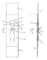
- FIG. 1 is the closure of a strap shown from metal tape, in particular steel tape.
- the Band strapping has overlapping ends 1, 2 on, with the ends to form a closure several in a row in the direction of the tape spaced, aligned and identical have shaped interlocking contour pairs 3.
- the Interlocking contour pairs are by the side of Band material separated, end with the Band material connected, from the level of Protruding strip material parts formed.
- the interlocking contour pair in the middle in FIGS. 1 and 2 3 is directed transversely to the band plane Deformation zone 4 in the longitudinal direction of the band 1, 2 immovably locked so that not only one Locking device in the pulling direction by the Interlocking contours 3, but also one Locking device in the direction of thrust through the Deformation zone 4 is reached.
- the deformation zone 4 preferably has the shape of a cone with a rounded tip. Furthermore the deformation zone 4 is formed such that in in the direction of the deformation zone 4 above Tape end 1 a tearing or breaking open Material is done, resulting in additional security of the locking system is advantageous.
- Each interlocking contour 3 is made of one on both Ends connected in one piece to the strip material Die cut strips formed, the Longitudinal edge edges 5 a narrow partial strip and its longitudinal side edge 6 a wider Partial strips with parallel edges form, the transition 7 between the Partial stripes due to an offset of the Edge margin is formed.
- Deformation zone 4 is in the area of the wide partial stripes through the cut edges 6 are formed, the overlapping Band ends formed.
- the height of the deformation zone corresponds to how seen across the band plane in particular from Figure 1, at least the Thickness of the strip material, preferably double Strip material thickness.
- a corresponding device 8 for Tensioning the metal strip 1, 2 around a package 9 shown the device 8 is a tool includes which the cutting contours 3 and Deformation zone 4 generated. To make the The band ends to be connected are closed 1.2 placed on top of each other. Then the Closure contour pairs 3 cut free and deformed into a kind of wave, especially from Figure 1 can be seen, wherein during the Cutting process simultaneously the deformation zone 4 pressed into one of the closure contour pairs 3 becomes. As shown in particular from the illustration Figures 4 and 5 can be seen when training several spaced in series Closure contour pairs 3 first a first Band end of adjacent closure contour pair 3 cut free and deformed.
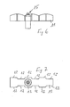
- the tool for making the The closure is in the functional position in FIGS. 4 and 5 and shown in detail in Figures 6 to 9.
- the tool has an upper knife 10 and Lower knife 11, with the band ends 1.2 at open tool between upper knife 10 and Lower knife 11 can be inserted.
- the lower knife 11 is a solid molded body with edges Cutting edges 12 and corrugated top, as in Figure 6 can be seen particularly clearly.
- the Upper knife 10 is a shaped body with one of the shape of the lower knife 11 adapted recess 13 and Cutting edges 14 on the edge of the recess 13, wherein the cutting edges or the areas supporting them of the upper knife in the opposite direction to the waveform of the Lower knife 11 are selected, in particular from the representation according to Figures 4 and 5 can be seen.
- the upper knife 10 On the lower knife 11 there is also a spike Projection 15 provided over the top of the Protrudes lower knife 11, the upper knife 10 has a free space 16 into which the spike-like Projection 15 can engage.
- the free space 16 can also through a matrix-like socket or sleeve be educated.
- the projection 15 has a cylindrical shaft on between the Cutting edges 12 of the lower knife 11 fixed to the frame or is held on the lower knife and the approximate is as wide as the distance between the sides Cutting edges 12 in the area of the projection 15 from each other.
- the shaft is tapered at the end, with the Taper forms the projection 15 and over the Top of the lower knife 11 protrudes.
- the summit of the protrusion thus formed is preferable flattened.
- the training according to the invention makes it possible in simply a conventional tool which for the production of the interlocking contour pairs 3 has suitable cutting edges, in a simple manner retrofit with parts 15 and 16, so that too existing tools in a simple way can be trained that the desired Closure lock is to be generated with it. Also at of new tools is this Training advantageous because the Interlocking contour pairs 3 and the corresponding Cutting contours are each identical and are therefore easy to control and a reliable closure guarantee.
- the invention is not limited to the exemplary embodiments limited, but within the scope of the revelation often variable.
Landscapes
- Engineering & Computer Science (AREA)
- Mechanical Engineering (AREA)
- Basic Packing Technique (AREA)
- Package Frames And Binding Bands (AREA)
- Clamps And Clips (AREA)
Applications Claiming Priority (2)
| Application Number | Priority Date | Filing Date | Title |
|---|---|---|---|
| DE10259598A DE10259598A1 (de) | 2002-12-19 | 2002-12-19 | Verschluss einer Bandumreifung |
| DE10259598 | 2002-12-19 |
Publications (2)
| Publication Number | Publication Date |
|---|---|
| EP1431205A2 true EP1431205A2 (fr) | 2004-06-23 |
| EP1431205A3 EP1431205A3 (fr) | 2006-08-02 |
Family
ID=32336476
Family Applications (1)
| Application Number | Title | Priority Date | Filing Date |
|---|---|---|---|
| EP03018067A Withdrawn EP1431205A3 (fr) | 2002-12-19 | 2003-08-08 | Ruban de cerclage |
Country Status (9)
| Country | Link |
|---|---|
| US (2) | US20040117950A1 (fr) |
| EP (1) | EP1431205A3 (fr) |
| JP (1) | JP2004231294A (fr) |
| KR (1) | KR20040054541A (fr) |
| CA (1) | CA2452317A1 (fr) |
| DE (1) | DE10259598A1 (fr) |
| PL (1) | PL364133A1 (fr) |
| RU (1) | RU2003130452A (fr) |
| YU (1) | YU78503A (fr) |
Cited By (1)
| Publication number | Priority date | Publication date | Assignee | Title |
|---|---|---|---|---|
| EP1857367A3 (fr) * | 2006-05-09 | 2008-11-19 | Illinois Tool Works Inc. | Outil de connection sans fermeture séparée à force réduite |
Families Citing this family (2)
| Publication number | Priority date | Publication date | Assignee | Title |
|---|---|---|---|---|
| US8788306B2 (en) * | 2007-03-05 | 2014-07-22 | International Business Machines Corporation | Updating a forecast model |
| US9656591B1 (en) | 2015-08-27 | 2017-05-23 | Jayson Dumenigo | Securing strap having at least one strap securing interface |
Citations (1)
| Publication number | Priority date | Publication date | Assignee | Title |
|---|---|---|---|---|
| DE3546021A1 (de) | 1985-12-24 | 1987-06-25 | Acme P W Lenzen Gmbh & Co Kg | Bandabschnitt aus metall zur bildung einer ballen-umschnuerung |
Family Cites Families (25)
| Publication number | Priority date | Publication date | Assignee | Title |
|---|---|---|---|---|
| US283651A (en) * | 1883-08-21 | William a | ||
| US119844A (en) * | 1871-10-10 | Improvement in metallic hoops | ||
| US548483A (en) * | 1895-10-22 | Ernest h | ||
| US995691A (en) * | 1909-11-22 | 1911-06-20 | Edgar Latham | Bale-tie. |
| US1178398A (en) * | 1912-11-22 | 1916-04-04 | E & B Holmes Machinery Company | Barrel-hoop. |
| US1393791A (en) * | 1917-03-01 | 1921-10-18 | Nat Binding Machine Company | Spliced joint for bale-bands |
| US2276988A (en) * | 1940-09-07 | 1942-03-17 | Signode Steel Strapping Co | Sleeveless strap joint |
| US2574572A (en) * | 1947-05-10 | 1951-11-13 | Englander Co Inc | Construction for connecting wire members together and method of producing and assembling the same |
| US2688890A (en) * | 1952-08-09 | 1954-09-14 | Ivan A Williams | Method of uniting superimposed metal sheets |
| DE1102643B (de) * | 1954-11-06 | 1961-03-16 | Lennart Reinhold Kalb | Huelsenloser Bandverschluss |
| US3031671A (en) * | 1956-12-05 | 1962-05-01 | Acme Steel Co | Spring clip fastener and method of forming same |
| US2815568A (en) * | 1957-03-12 | 1957-12-10 | Bianca Edoardo Ginseppe | Process of joining or uniting metallic sheets |
| US3188706A (en) * | 1962-06-29 | 1965-06-15 | Universal Steel Strapping Inc | Fastenerless splice and method of forming same |
| US3534466A (en) * | 1967-04-18 | 1970-10-20 | Edward J Ardolino | Method of fastening sheet material |
| US3719986A (en) * | 1970-07-13 | 1973-03-13 | E Ardolino | Method of joining sheet-like areas |
| US3728779A (en) * | 1970-11-23 | 1973-04-24 | Behlen Mfg Co | Method of joining strip material |
| US3726000A (en) * | 1971-05-25 | 1973-04-10 | O Hafner | Means for fastening overlying metal sheets |
| DE2256983C2 (de) * | 1972-11-21 | 1975-02-13 | Titan Verpackungssysteme Gmbh, 5830 Schwelm | Hebeband für schwere Lasten |
| JPS6458615A (en) * | 1987-08-26 | 1989-03-06 | Sumitomo Metal Ind | Engagement structure for bundling metal strap |
| US5138746A (en) * | 1990-04-06 | 1992-08-18 | Nkh Spring Co., Ltd. | Clamp structure |
| US5117536A (en) * | 1991-04-22 | 1992-06-02 | Signode Corporation | Binding strap with integral connecting structure and anti-disengagement feature |
| ES2126434B1 (es) * | 1995-05-26 | 2000-01-01 | Mikalor Sa | Mejoras introducidas en los medios de abrochado de los extremos de la lamina formativa de abrazaderas de banda metalica. |
| US6178601B1 (en) * | 1999-07-09 | 2001-01-30 | Paul M. Craig, Jr. | Mechanical connection for open clamps |
| JP4499880B2 (ja) * | 2000-07-05 | 2010-07-07 | 日本発條株式会社 | ブーツバンド |
| EP1364877B1 (fr) * | 2002-05-24 | 2007-06-13 | Orgapack GmbH | Outil de poinçonnage pour un dispositif de cerclage |
-
2002
- 2002-12-19 DE DE10259598A patent/DE10259598A1/de not_active Withdrawn
-
2003
- 2003-08-08 EP EP03018067A patent/EP1431205A3/fr not_active Withdrawn
- 2003-10-07 YU YU78503A patent/YU78503A/sh unknown
- 2003-10-14 RU RU2003130452/12A patent/RU2003130452A/ru not_active Application Discontinuation
- 2003-12-02 US US10/726,816 patent/US20040117950A1/en not_active Abandoned
- 2003-12-05 CA CA002452317A patent/CA2452317A1/fr not_active Abandoned
- 2003-12-11 JP JP2003436404A patent/JP2004231294A/ja active Pending
- 2003-12-17 KR KR1020030092483A patent/KR20040054541A/ko not_active Withdrawn
- 2003-12-18 PL PL03364133A patent/PL364133A1/xx not_active Application Discontinuation
-
2006
- 2006-04-04 US US11/397,839 patent/US20060179616A1/en not_active Abandoned
Patent Citations (1)
| Publication number | Priority date | Publication date | Assignee | Title |
|---|---|---|---|---|
| DE3546021A1 (de) | 1985-12-24 | 1987-06-25 | Acme P W Lenzen Gmbh & Co Kg | Bandabschnitt aus metall zur bildung einer ballen-umschnuerung |
Cited By (1)
| Publication number | Priority date | Publication date | Assignee | Title |
|---|---|---|---|---|
| EP1857367A3 (fr) * | 2006-05-09 | 2008-11-19 | Illinois Tool Works Inc. | Outil de connection sans fermeture séparée à force réduite |
Also Published As
| Publication number | Publication date |
|---|---|
| US20040117950A1 (en) | 2004-06-24 |
| DE10259598A1 (de) | 2004-07-01 |
| EP1431205A3 (fr) | 2006-08-02 |
| CA2452317A1 (fr) | 2004-06-19 |
| US20060179616A1 (en) | 2006-08-17 |
| YU78503A (sh) | 2004-11-25 |
| JP2004231294A (ja) | 2004-08-19 |
| PL364133A1 (en) | 2004-06-28 |
| RU2003130452A (ru) | 2005-03-27 |
| KR20040054541A (ko) | 2004-06-25 |
Similar Documents
| Publication | Publication Date | Title |
|---|---|---|
| DE2502663C2 (de) | Befestiger | |
| EP0818359B1 (fr) | Couvercle pour module de coussin gonflable | |
| DE3120971C2 (fr) | ||
| DE3129907C2 (de) | Verschluss für Reifenketten | |
| DE3709536A1 (de) | Zugschlossanordnung | |
| DE1785533B1 (de) | Trennbares Endglied fuer Reissverschluesse | |
| DE3521653A1 (de) | Dorn fuer ein befestigungselement, bestehend aus dorn und aufgepresstem rohrfoermigem glied | |
| EP3186160A1 (fr) | Bride de serrage | |
| DE69708164T2 (de) | Spannband mit ineinandergreifenden Enden | |
| DE3718179A1 (de) | Verbesserungen in verbindung mit gittertafelbruecken | |
| AT389805B (de) | Reissverschluss | |
| DE2717564B2 (de) | Verschlußlose Bandverbindung | |
| DE2613571A1 (de) | Kunststoff-garantieverschluss | |
| EP0616796A1 (fr) | Bande d'étanchéité | |
| DE2303797C3 (fr) | ||
| EP1431205A2 (fr) | Ruban de cerclage | |
| DE3042839C2 (de) | Verschlußkappe | |
| DE3049066A1 (de) | Kabelband aus flexiblem, hartelastischem kunststoff | |
| DE2012850C3 (de) | Reißverschluß mit Verschlußgliederreihen aus schraubenlinienförmig verformten Kunststoffmonofilament | |
| DE2645454C3 (de) | Verfahren zum Thermoformen von kontinuierlichen Reißverschlußgliederreihen aus Kunststoffmonofilament | |
| DE2104150C2 (de) | Druckknopfähnlicher Verschluß | |
| DE3802798A1 (de) | Verfahren und vorrichtung zum verbinden von bauelementen insbesondere von pfetten und wandriegeln | |
| DE3309055A1 (de) | Verriegelungssystem | |
| DE910276C (de) | Sicherheitsplombe | |
| DE856391C (de) | Riemenverbinde-Maschine mit einem vorzugsweise roehrenfoermigen Kamm |
Legal Events
| Date | Code | Title | Description |
|---|---|---|---|
| PUAI | Public reference made under article 153(3) epc to a published international application that has entered the european phase |
Free format text: ORIGINAL CODE: 0009012 |
|
| AK | Designated contracting states |
Kind code of ref document: A2 Designated state(s): AT BE BG CH CY CZ DE DK EE ES FI FR GB GR HU IE IT LI LU MC NL PT RO SE SI SK TR |
|
| AX | Request for extension of the european patent |
Extension state: AL LT LV MK |
|
| PUAL | Search report despatched |
Free format text: ORIGINAL CODE: 0009013 |
|
| AK | Designated contracting states |
Kind code of ref document: A3 Designated state(s): AT BE BG CH CY CZ DE DK EE ES FI FR GB GR HU IE IT LI LU MC NL PT RO SE SI SK TR |
|
| AX | Request for extension of the european patent |
Extension state: AL LT LV MK |
|
| 17P | Request for examination filed |
Effective date: 20061006 |
|
| 17Q | First examination report despatched |
Effective date: 20061201 |
|
| AKX | Designation fees paid |
Designated state(s): AT BE BG CH CY CZ DE DK EE ES FI FR GB GR HU IE IT LI LU MC NL PT RO SE SI SK TR |
|
| RTI1 | Title (correction) |
Free format text: METHOD AND TOOL FOR MANUFACTURING A BUNDLE TIE |
|
| GRAP | Despatch of communication of intention to grant a patent |
Free format text: ORIGINAL CODE: EPIDOSNIGR1 |
|
| STAA | Information on the status of an ep patent application or granted ep patent |
Free format text: STATUS: THE APPLICATION IS DEEMED TO BE WITHDRAWN |
|
| 18D | Application deemed to be withdrawn |
Effective date: 20080704 |