EP1431233B1 - Hydraulischer Seilantrieb für Aufzüge - Google Patents
Hydraulischer Seilantrieb für Aufzüge Download PDFInfo
- Publication number
- EP1431233B1 EP1431233B1 EP20030028881 EP03028881A EP1431233B1 EP 1431233 B1 EP1431233 B1 EP 1431233B1 EP 20030028881 EP20030028881 EP 20030028881 EP 03028881 A EP03028881 A EP 03028881A EP 1431233 B1 EP1431233 B1 EP 1431233B1
- Authority
- EP
- European Patent Office
- Prior art keywords
- drive
- hydraulic
- motor
- cable
- hub
- Prior art date
- Legal status (The legal status is an assumption and is not a legal conclusion. Google has not performed a legal analysis and makes no representation as to the accuracy of the status listed.)
- Expired - Lifetime
Links
- 239000010720 hydraulic oil Substances 0.000 claims description 2
- 230000001419 dependent effect Effects 0.000 description 2
- 239000003921 oil Substances 0.000 description 2
- 229910000831 Steel Inorganic materials 0.000 description 1
- 230000005540 biological transmission Effects 0.000 description 1
- 238000010276 construction Methods 0.000 description 1
- 230000008878 coupling Effects 0.000 description 1
- 238000010168 coupling process Methods 0.000 description 1
- 238000005859 coupling reaction Methods 0.000 description 1
- 230000007547 defect Effects 0.000 description 1
- 230000000694 effects Effects 0.000 description 1
- 239000012530 fluid Substances 0.000 description 1
- 238000012423 maintenance Methods 0.000 description 1
- 239000010959 steel Substances 0.000 description 1
- 239000000725 suspension Substances 0.000 description 1
Images
Classifications
-
- B—PERFORMING OPERATIONS; TRANSPORTING
- B66—HOISTING; LIFTING; HAULING
- B66B—ELEVATORS; ESCALATORS OR MOVING WALKWAYS
- B66B11/00—Main component parts of lifts in, or associated with, buildings or other structures
- B66B11/04—Driving gear ; Details thereof, e.g. seals
- B66B11/0423—Driving gear ; Details thereof, e.g. seals actuated pneumatically or hydraulically
Definitions
- the invention relates to a hydraulic cable drive for elevators, with a traction sheave, at least one braking device and at least one hydraulic motor.
- Such a cable drive is for example in the DE-U 69 27 188 disclosed.
- a traction sheave for passenger and goods lifts which uses a slow-running hydraulic motor to drive, the outer housing is firmly connected to a traction sheave.
- the traction sheave is equipped with a braking device.
- the axis of the hydraulic motor is clamped on both sides of the traction sheave in two bearing blocks.
- the traction sheave rotates with the housing of the hydraulic motor.
- Object of the present invention is therefore to provide a hydraulic cable drive for elevators available that is suitable for mounting in the elevator shaft by a compact structure and does not have the disadvantages described above.
- the power density of a hydraulic motor which is up to a factor of 20 higher than that of conventional electric motors, enables direct coupling of the drive shaft to the hub of the traction sheave, thereby eliminating the need for a gearbox, resulting in a very compact drive structure.
- the integrated in the traction sheave braking device ensures next to the compact design for extra security, as well as in the event of breakage of the output shaft of the elevator safely held by the brake will and can not crash. It is also possible to easily maintain the engine and replace it if necessary, without having to dismantle the entire elevator drive.
- brake integrated into the motor allows a particularly cost-effective implementation of the drive. When using a corresponding deep-drawn hub of the drive motor protrudes only slightly out of the traction sheave.
- the hub of the traction sheave is mounted on the outside in a projecting into the interior of the traction sheave, the motor housing bearing mounting block, a particularly compact construction of the drive is given.
- the fastening element also carries the brake in addition to the motor housing and the traction sheave. With the fastener secure mounting of the drive in the elevator shaft is possible.
- the braking device has a drum brake arranged between the hub and the drive pulley rim.
- Such an integrated drum brake is characterized by a particularly low space requirement, since it does not increase in particular the overall depth of the drive.
- the brake device has a brake disk arranged on the outside of the traction sheave.
- a brake disk arranged on the outside of the traction sheave.
- Such an additional or alternative to the drum brake mounted outer brake disc may be useful depending on the application. In addition to increasing the braking power with good metering, it can improve the system performance of the drive, especially in heavily frequented elevators.
- an orbital or a vane motor or a slow-running axial or radial piston engine is provided with a high number of chambers as a motor.
- the different motors with their specific advantages and disadvantages can be used for the drive.
- the slow-running axial or radial piston motors with a high number of chambers due to their high power density, are particularly useful for elevator arrangements in which a direct 1: 1 ratio between counterweight and elevator is used.
- Fast rotating engines are advantageous in a 2: 1 suspension of the cab to the counterweight.
- a hydraulic control valve is arranged directly on the drive.
- the direct arrangement of the control valve on the drive ensures good stability in the control loop. Too long cable routes Namely between the hydraulic motor and the corresponding control valves can lead to mechanical vibrations in this hydraulic circuit, which should be avoided if possible. Due to the direct arrangement on the drive preferred by rigid pipe connections as possible between the engine and valve, such vibrations can effectively prevent and ensure good controllability of the drive in all operating ranges.
- sensors are provided for detecting engine speed and / or hydraulic pressure and / or hydraulic oil temperature and / or valve control variables and possibly further system variables.
- By detecting the system states it is possible to ensure accurate control of the elevator.
- speed and other system sizes can be compensated by measuring pressure, temperature and valve position corresponding disturbances in the system. A safe lift operation is guaranteed even under heavy use of the system and thus increased oil temperature, because the resulting lower oil viscosity can be compensated.
- An embodiment of the conveyor drive provides that for controlling the hydraulic control valve an optionally integrated in this electronic control device, in particular a microcontroller, is provided.
- a microcontroller in conjunction with an electro-hydraulic control valve allows flexible control and regulation of the elevator.
- the drive system can be configured for a wide range of application areas and achieve a correspondingly flexible system structure.
- the control problems that occur ie the loading and direction of travel, dependent operation of the engine as a brake or drive in advance or reverse direction controlled by a microcontroller safely.
- the invention also relates to an elevator with an elevator shaft and an elevator car and a cable drive described above, which is characterized in that the drive is provided in the elevator shaft.
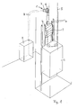
- a generally designated 1 inventive cable drive is, as shown in Fig. 1, mounted in the shaft head of a hoistway.
- an elevator car 2 and a counterweight 3 are arranged, which has approximately the same mass as the elevator car plus half their maximum payload. Both the elevator car and the counterweight are vertically displaceable guided in rails 4.
- a supporting cable 5 is guided from its one-sided attachment in the shaft head via rollers on the elevator car via a traction sheave 6 of the drive 1 to a deflection roller fixed to the counterweight 3 and from here to its second attachment in the shaft head.
- a flat belt with steel wire inserts can also be used.
- the traction sheave 6 of the drive 1 is driven and decelerated by a hydraulic motor 7. Via supply lines 8 hydraulic fluid is passed from a pressure medium supply 9 to the motor 7.
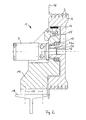
- the structure of the cable drive according to the invention is shown in more detail in Fig. 2.
- the traction sheave 6 is preferably rotatably mounted with spherical roller bearings 10 in a mounting block 11.
- a motor shaft 12 of the hydraulic motor 7 is positively connected (key 13a) with the hub 13 of the traction sheave, so that a power transmission in both directions of rotation between the motor 7 and the traction sheave 6 is possible.
- a drum brake device is also arranged.
- a circumferential outer edge of the traction sheave 6 is formed as a brake disc 16.
- the masses attached to the supporting cables 5 can not crash even in the event of breakage of the shaft 12 or other defect of the drive motor 7, but are held in their position by the brakes.
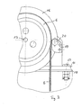
- the mounting block 11 has fastening screws 17 in the lower section, with which it can be fastened on a support 18 in the shaft head, as shown in more detail in FIG.
- the outside attached to the traction sheave disc 16 is held by a braking device 19 by two hydraulically vented brake shoes 20.
- the invention is not limited to the embodiment, but can be modified in many ways without departing from the spirit.
- different hydraulic motors can be used.
- the dimensions and embodiments of the traction sheave, the braking devices such as motor-integrated designs, or the like. can be varied depending on the purpose.
Landscapes
- Engineering & Computer Science (AREA)
- Civil Engineering (AREA)
- Mechanical Engineering (AREA)
- Structural Engineering (AREA)
- Cage And Drive Apparatuses For Elevators (AREA)
- Braking Arrangements (AREA)
Description
- Die Erfindung betrifft einen hydraulischen Seilantrieb für Aufzüge, mit einer Treibscheibe, wenigstens einer Bremseinrichtung und wenigstens einem Hydromotor.
- Ein solcher Seilantrieb ist beispielsweise in der
DE-U 69 27 188 offenbart. In dieser Schrift ist eine Treibscheibenwinde für Personen- und Lastenaufzüge beschrieben, die zum Antrieb einen langsam laufenden Hydromotor verwendet, dessen äußeres Gehäuse fest mit einer Treibscheibe verbunden ist. Die Treibscheibe ist mit einer Bremseinrichtung ausgestattet. Die Achse des Hydromotors ist beidseitig der Treibscheibe in zwei Lagerböcke eingespannt. Die Treibscheibe dreht sich mit dem Gehäuse des Hydromotors. Dieser Antrieb baut groß und schwer, der Hydromotor ist bei Wartung und Instandhaltung nicht erreichbar und damit für einen maschinenraumlosen Aufzug unbrauchbar. - Aus
DE 198 46 671 A1 ist eine Treibscheibe mit integrierter Bremseinrichtung bekannt, die groß, schwer, kompliziert und dadurch teuer ist. Sie ist nicht als kompakter Antrieb in einem Aufzugschacht geeignet. Eine ähnliche nachteilige Lösung ist ausJP 11157766 - Aufgabe der vorliegenden Erfindung ist es daher, einen hydraulischen Seilantrieb für Aufzüge zur Verfügung zu stellen, der sich durch einen kompakten Aufbau für eine Montage im Aufzugschacht eignet und die vorbeschriebenen Nachteile nicht aufweist.
- Diese Aufgabe wird bei einem hydraulischen Seilantrieb der eingangs bezeichneten Art dadurch gelöst, dass die Abtriebswelle des Hydromotors direkt mit der Nabe der Treibscheibe innenseitig der Nabe gekuppelt und die Bremseinrichtung in die Treibscheibe oder in den Hydromotor integriert ist, wobei die Nabe der Treibscheibe außenseitig in einem in das Innere der Treibscheibe hineinragenden, das Motorgehäuse tragenden Befestigungsblock gelagert ist.
- Die im Vergleich zu herkömmlichen Elektromotoren bis um den Faktor 20 höhere Leistungsdichte eines Hydromotors ermöglicht die direkte Kupplung der Antriebswelle mit der Nabe der Treibscheibe und dadurch den Verzicht auf ein Getriebe, was zu einem sehr kompakten Antriebsaufbau führt. Die in die Treibscheibe integrierte Bremseinrichtung sorgt neben dem kompakten Aufbau für eine zusätzliche Sicherheit, da auch im Falle des Bruches der Abtriebswelle der Aufzug von der Bremse sicher gehalten wird und nicht abstürzen kann. Es ist außerdem möglich, den Motor einfach zu warten und ggf. auszutauschen, ohne den kompletten Aufzugsantrieb demontieren zu müssen. Eine in den Motor integrierte Bremse ermöglicht demgegenüber eine besonders kostengünstige Realisierung des Antriebes. Bei der Verwendung einer entsprechend tiefgezogenen Nabe ragt der Antriebsmotor nur geringfügig aus der Treibscheibe hinaus.
- Dadurch, dass die Nabe der Treibscheibe außenseitig in einem in das Innere der Treibscheibe hineinragenden, das Motorgehäuse tragenden Befestigungsblock gelagert ist, ist ein besonders kompakter Aufbau des Antriebes gegeben. Das Befestigungselement trägt neben dem Motorgehäuse und der Treibscheibe ggf. auch die Bremse. Mit dem Befestigungselement ist eine sichere Montage des Antriebes im Aufzugschacht möglich.
- Vorteilhafte Ausgestaltungen der Erfindung ergeben sich aus den Unteransprüchen.
- So kann bevorzugt vorgesehen sein, dass die Bremseinrichtung eine zwischen der Nabe und dem Treibscheibenkranz angeordnete Trommelbremse aufweist. Eine solche integrierte Trommelbremse zeichnet sich durch einen besonders geringen Raumbedarf aus, da sie insbesondere die Bautiefe des Antriebes nicht vergrößert.
- In einer weiteren Ausgestaltung der Erfindung ist vorgesehen, dass die Bremseinrichtung eine an der Außenseite der Treibscheibe angeordnete Bremsscheibe aufweist. Eine solche zusätzlich oder alternativ zur Trommelbremse angebrachte äußere Bremsscheibe kann je nach Einsatzzweck sinnvoll sein. Neben einer Verstärkung der Bremsleistung bei gleichzeitig guter Dosierbarkeit kann sie insbesondere bei stark frequentierten Aufzügen die Systemleistung des Antriebes verbessern.
- Zweckmäßig kann es sein, dass als Motor ein Orbital- oder ein Flügelzellenmotor oder ein langsam laufender Axial- oder Radialkolbenmotor mit hoher Kammernzahl vorgesehen ist. Abhängig vom Einsatzzweck sind die unterschiedlichen Motoren mit ihren spezifischen Vor- und Nachteilen für den Antrieb verwendbar. So sind die langsam laufenden Axial- oder Radialkolbenmotoren mit hoher Kammernzahl durch ihre hohe Leistungsdichte besonders für Aufzuganordnungen sinnvoll, bei denen eine direkte 1:1-Übersetzung zwischen Gegengewicht und Aufzug verwandt wird. Schneller drehende Motoren sind bei einer 2:1-Aufhängung der Kabine zum Gegengewicht vorteilhaft.
- Es kann vorteilhaft vorgesehen sein, dass ein hydraulisches Regelventil direkt am Antrieb angeordnet ist. Die direkte Anordnung des Regelventils am Antrieb sorgt für eine gute Stabilität im Regelkreis. Zu lange Leitungswege zwischen dem Hydraulikmotor und den entsprechenden Regelventilen können nämlich zu mechanischen Schwingungen in diesem Hydraulikkreis führen, was es möglichst zu vermeiden gilt. Durch die direkte Anordnung am Antrieb bevorzugt durch möglichst starre Rohrverbindungen zwischen Motor und Ventil, lassen sich solche Schwingungen wirksam verhindern und eine gute Regelbarkeit des Antriebs in allen Betriebsbereichen gewährleisten.
- Sinnvoll ist es, dass Sensoren zur Erfassung von Motordrehzahl und/oder Hydraulikdruck und/oder Hydrauliköltemperatur und/oder Ventilstellgrößen sowie ggf. weiterer Systemgrößen vorgesehen sind. Durch die Erfassung der Systemzustände ist es möglich, eine genaue Regelung des Aufzuges zu gewährleisten. Neben der Motordrehzahl, die in Verbindung mit der Kabinengeschwindigkeit zur Regelung der Aufzugsposition, -geschwindigkeit und weiterer Systemgrößen benutzt wird, lassen sich durch die Messung von Druck, Temperatur und Ventilstellung entsprechende Störgrößen im System kompensieren. Ein sicherer Aufzugbetrieb wird auch bei starker Beanspruchung des Systems und dadurch gestiegener Öltemperatur garantiert, weil die resultierende geringere Öl-Viskosität ausgeglichen werden kann.
- Eine Ausgestaltung des Förderantriebes sieht vor, dass zur Steuerung des hydraulischen Regelventils eine ggf. in dieses integrierte, elektronische Steuereinrichtung, insbesondere ein Microcontroller, vorgesehen ist. Ein Microcontroller in Verbindung mit einem elektrohydraulischen Regelventil ermöglicht eine flexible Steuerung und Regelung des Aufzuges. So läßt sich das Antriebssystem für eine weite Klasse von Anwendungsbereichen konfigurieren und ein entsprechend flexibler Systemaufbau erreichen. Bei dem bevorzugten Betrieb des Aufzuges im Vier-Quadranten-Betrieb, bei dem das Gegengewicht dem Kabinengewicht plus der halben maximalen Zuladung entspricht, lassen sich die auftretenden Regelprobleme, also vom Beladungs- und Fahrtrichtungszustand, abhängige Betriebsweise des Motors als Bremse oder Antrieb in Vor- oder Rückwärtsrichtung durch einen Microcontroller sicher beherrschen.
- Außerdem betrifft die Erfindung auch einen Aufzug mit einem Aufzugschacht und einer Aufzugskabine sowie einem vorbeschriebenen Seilantrieb, der sich dadurch auszeichnet, dass der Antrieb im Aufzugschacht vorgesehen ist.
- Die Anordnung des Antriebes im Aufzugschacht bietet eine Reihe von Vorteilen, insbesondere, dass kein Maschinenraum mehr vorgesehen sein muss, was die Kosten einer solchen Aufzuganlage erheblich reduziert. Solche Anordnungen werden allerdings erst durch den besonders kompakten Aufbau des erfindungsgemäßen Antriebes ermöglicht. Bis auf den Antrieb und das Ventil sind keine weiteren Komponenten neben Aufzug und Gegengewicht im Aufzugschacht nötig, da die Hydraulikversorgung an einem beliebigen, auch weiter entfernten Ort beherbergt sein kann.
- Die Erfindung ist nachstehend anhand der Zeichnung beispielhaft näher erläutert. Diese zeigt in
- Fig. 1
- eine dreidimensionale schematische Ansicht eines mit einem erfindungsgemäßen Seilantriebes angetriebenen Aufzuges,
- Fig. 2
- eine Seitenansicht, teilweise geschnitten, des erfindungsgemäßen Seilantriebes sowie in
- Fig. 3
- eine Teilvorderansicht des erfindungsgemäßen Antriebes.
- Ein allgemein mit 1 bezeichneter erfindungsgemäßer Seilantrieb ist, wie in Fig. 1 dargestellt, im Schachtkopf eines Aufzugschachtes montiert. In diesem Schacht sind eine Aufzugskabine 2 und ein Gegengewicht 3 angeordnet, das etwa dieselbe Masse besitzt, wie die Aufzugskabine plus ihrer halben maximalen Zuladung. Sowohl die Aufzugskabine als auch das Gegengewicht sind vertikal verschiebbar in Schienen 4 geführt.
- Ein Tragseil 5 wird von seiner einseitigen Befestigung im Schachtkopf über Rollen an der Aufzugskabine über eine Treibscheibe 6 des Antriebes 1 zu einer am Gegengewicht 3 befestigten Umlenkrolle und von hier zu seiner zweiten Befestigung im Schachtkopf geführt. Anstelle des Tragseils 5 kann auch ein Flachriemen mit Stahldrahteinlagen verwendet werden.
- Die Treibscheibe 6 des Antriebes 1 wird durch einen Hydraulikmotor 7 angetrieben und verzögert. Über Versorgungsleitungen 8 wird Hydraulikflüssigkeit von einer Druckmittelversorgung 9 zum Motor 7 geleitet.
- Der Aufbau des erfindungsgemäßen Seilantriebes ist in Fig. 2 näher dargestellt. Die Treibscheibe 6 ist vorzugsweise mit Pendelrollen-Kugellagern 10 in einem Befestigungsblock 11 drehbar gelagert. Eine Motorwelle 12 des hydraulischen Motors 7 ist formschlüssig (Passfeder 13a) mit der Nabe 13 der Treibscheibe verbunden, so dass eine Kraftübertragung in beide Drehrichtungen zwischen dem Motor 7 und der Treibscheibe 6 möglich ist.
- Im Befestigungsblock 11 ist außerdem eine Trommelbremseinrichtung angeordnet. Dazu werden hydraulisch belüftete Bremsblöcke 14 zum Bremsen von einer Feder 15 radial nach außen gegen das Innere der Treibscheibe 6 gepresst, wodurch diese gehalten wird. Ferner ist ein umlaufender äußerer Rand der Treibscheibe 6 als Bremsscheibe 16 ausgebildet.
- Durch die direkte Wirkung der Bremseinrichtungen auf die Treibscheibe 6 können auch im Falle eines Bruchs der Welle 12 oder sonstigen Defektes des Antriebsmotors 7 die an den Tragseilen 5 befestigten Massen nicht abstürzen, sondern werden durch die Bremsen in ihrer Position gehalten.
- Der Befestigungsblock 11 weist im unteren Abschnitt Befestigungsschrauben 17 auf, mit denen er auf einem Träger 18 im Schachtkopf befestigt werden kann, wie dies in Fig. 3 näher dargestellt ist.
- Die außen an der Treibscheibe angebrachte Bremsscheibe 16 wird von einer Bremseinrichtung 19 durch zwei hydraulisch entlüftete Bremsbacken 20 gehalten.
- Natürlich ist die Erfindung nicht auf das Ausführungsbeispiel beschränkt, sondern kann in vielfacher Hinsicht abgeändert werden, ohne den Grundgedanken zu verlassen. So sind insbesondere vom Einsatzzweck abhängig, unterschiedliche Hydraulikmotoren einsetzbar. Auch die Dimensionen und Ausgestaltungen der Treibscheibe, der Bremseinrichtungen wie im Motor integrierte Bauformen, o.ä. können vom Einsatzzweck abhängig variiert werden.
Claims (8)
- Hydraulischer Seilantrieb für Aufzüge, mit einer Treibscheibe, wenigstens einer Bremseinrichtung und wenigstens einem Hydromotor,
dadurch gekennzeichnet,
dass die Abtriebswelle (12) des Hydromotors (7) direkt mit der Nabe (13) der Treibscheibe (6) innenseitig der Nabe gekuppelt und die Bremseinrichtung in die Treibscheibe oder in den Hydromotor integriert ist, wobei die Nabe der Treibscheibe (6) außenseitig in einem in das Innere der Treibscheibe (6) hineinragenden, das Motorgehäuse tragenden Befestigungsblock (11) gelagert ist. - Seilantrieb nach Anspruch 1,
dadurch gekennzeichnet,
dass die Bremseinrichtung eine zwischen der Nabe (13) und dem Treibscheibenkranz angeordnete Trommelbremse (14) aufweist. - Seilantrieb nach Anspruch 1 oder 2,
dadurch gekennzeichnet,
dass die Bremseinrichtung eine an der Außenseite der Treibscheibe (6) angeordnete Bremsscheibe (16) aufweist. - Seilantrieb nach einem der vorangehenden Ansprüche,
dadurch gekennzeichnet,
dass als Motor (7) ein Orbital- oder Flügelzellenmotor oder langsam laufender Axial- und/oder Radialkolbenmotor mit hoher Kammernzahl vorgesehen ist. - Seilantrieb nach einem der vorangehenden Ansprüche,
dadurch gekennzeichnet,
dass ein hydraulisches Regelventil direkt am Antrieb (1) angeordnet ist. - Seilantrieb nach einem der vorangehenden Ansprüche,
dadurch gekennzeichnet,
dass Sensoren zur Erfassung von Motordrehzahl und/oder Hydraulikdruck und/oder Hydrauliköltemperatur und/oder Ventilstellgrößen sowie ggf. weiterer Systemgrößen vorgesehen sind. - Seilantrieb nach einem der vorangehenden Ansprüche,
dadurch gekennzeichnet,
dass zur Steuerung des hydraulischen Regelventils eine ggf. in dieses integrierte, elektronische Steuereinrichtung, insbesondere ein Microcontroller, vorgesehen ist. - Aufzug mit einem Aufzugschacht und einer Aufzugskabine sowie mit einem Seilantrieb nach einem der vorangehenden Ansprüche,
dadurch gekennzeichnet,
dass der Antrieb (1) im Aufzugschacht vorgesehen ist.
Applications Claiming Priority (2)
| Application Number | Priority Date | Filing Date | Title |
|---|---|---|---|
| DE2002159147 DE10259147A1 (de) | 2002-12-18 | 2002-12-18 | Hydraulischer Seilantrieb für Aufzüge |
| DE10259147 | 2002-12-18 |
Publications (2)
| Publication Number | Publication Date |
|---|---|
| EP1431233A1 EP1431233A1 (de) | 2004-06-23 |
| EP1431233B1 true EP1431233B1 (de) | 2007-11-21 |
Family
ID=32336429
Family Applications (1)
| Application Number | Title | Priority Date | Filing Date |
|---|---|---|---|
| EP20030028881 Expired - Lifetime EP1431233B1 (de) | 2002-12-18 | 2003-12-16 | Hydraulischer Seilantrieb für Aufzüge |
Country Status (2)
| Country | Link |
|---|---|
| EP (1) | EP1431233B1 (de) |
| DE (2) | DE10259147A1 (de) |
Families Citing this family (3)
| Publication number | Priority date | Publication date | Assignee | Title |
|---|---|---|---|---|
| CN109607361B (zh) * | 2018-12-21 | 2023-11-10 | 广东富士电梯有限公司 | 一种具有涂油及挡绳功能的电梯轿厢顶轮装置 |
| CN114380175A (zh) * | 2022-01-26 | 2022-04-22 | 湖州巨人电机有限公司 | 电梯曳引机断裂保护结构 |
| DE102023125048A1 (de) * | 2023-09-15 | 2025-03-20 | Avs Hydraulikmotorenbau Gmbh | Bremsvorrichtung für einen hydraulikmotor |
Family Cites Families (6)
| Publication number | Priority date | Publication date | Assignee | Title |
|---|---|---|---|---|
| JPS63106289A (ja) * | 1986-10-22 | 1988-05-11 | 株式会社日立製作所 | 流体圧エレベ−タ |
| DE19827497B4 (de) * | 1997-06-19 | 2005-02-17 | Wittur Ag | Aufzug |
| JPH11157766A (ja) * | 1997-11-28 | 1999-06-15 | Hitachi Ltd | 巻上機 |
| DE19846671A1 (de) * | 1998-10-09 | 2000-04-13 | Erhard Mueller | Treibscheibenbremse mit erhöhter Redundanz |
| JP2000247559A (ja) * | 1999-02-24 | 2000-09-12 | Hitachi Ltd | エレベータ装置 |
| JP2001355659A (ja) * | 2000-04-27 | 2001-12-26 | Inventio Ag | エレベーター駆動装置用ディスクブレーキ |
-
2002
- 2002-12-18 DE DE2002159147 patent/DE10259147A1/de not_active Withdrawn
-
2003
- 2003-12-16 DE DE50308637T patent/DE50308637D1/de not_active Expired - Lifetime
- 2003-12-16 EP EP20030028881 patent/EP1431233B1/de not_active Expired - Lifetime
Also Published As
| Publication number | Publication date |
|---|---|
| DE10259147A1 (de) | 2004-10-07 |
| DE50308637D1 (de) | 2008-01-03 |
| EP1431233A1 (de) | 2004-06-23 |
Similar Documents
| Publication | Publication Date | Title |
|---|---|---|
| DE69403684T3 (de) | Aufzugsmotor im Gegengewicht eingesetzt | |
| DE69420329T2 (de) | Im Gegengewicht eingebauter Aufzugsmotor | |
| EP1621509B1 (de) | Anordnung von einer Antriebsmaschine einer Aufzugsanlage | |
| DE19632850C2 (de) | Treibscheibenaufzug ohne Gegengewicht | |
| DE69909133T2 (de) | Aufzugsantrieb mit gegenläufigen rotoren | |
| EP3317222B1 (de) | Hubwindenanordnung | |
| EP0706968B1 (de) | Antriebseinheit für ein Hebezeug | |
| DE19811977A1 (de) | Schneckengetriebe | |
| DE69427042T2 (de) | Aufzugsantrieb mit gleitverhinderung | |
| EP0078874A2 (de) | Winde für einen Personen- oder Lastenaufzug | |
| EP1431233A1 (de) | Hydraulischer Seilantrieb für Aufzüge | |
| EP1069068A1 (de) | Kompakter Antrieb für einen Aufzug | |
| EP0949181B1 (de) | Antrieb für einen Aufzug mit einem an Seilen gehaltenen Fahrkorb | |
| WO2021180565A1 (de) | Antriebseinheit sowie bau- und/oder materialumschlagsmaschine mit einer solchen antriebseinheit | |
| DE19846671A1 (de) | Treibscheibenbremse mit erhöhter Redundanz | |
| DE3342172C2 (de) | Elektrischer Fahrantrieb für einen Kran oder das Fahrwerk eines Hubwerkes etc. | |
| EP0758623A1 (de) | Hebezeug, das mit einem Zugmittel betrieben ist | |
| EP2089305A1 (de) | Antrieb für aufzüge | |
| EP1156978B1 (de) | Hebezeugantrieb | |
| EP1627841B1 (de) | Antrieb für eine Aufzugsanlage | |
| DE102009048089A1 (de) | Seilbremse für ein Aufzugsystem | |
| CH624745A5 (en) | Clutch, in particular for small electric hoists | |
| EP3235770B1 (de) | Verfahren zur nachrüstung eines aufzugs und korrespondierender aufzug | |
| EP1774999A1 (de) | Antriebseinheit | |
| DE202004005300U1 (de) | Aufzugsantriebseinheit |
Legal Events
| Date | Code | Title | Description |
|---|---|---|---|
| PUAI | Public reference made under article 153(3) epc to a published international application that has entered the european phase |
Free format text: ORIGINAL CODE: 0009012 |
|
| AK | Designated contracting states |
Kind code of ref document: A1 Designated state(s): AT BE BG CH CY CZ DE DK EE ES FI FR GB GR HU IE IT LI LU MC NL PT RO SE SI SK TR |
|
| AX | Request for extension of the european patent |
Extension state: AL LT LV MK |
|
| 17P | Request for examination filed |
Effective date: 20041217 |
|
| AKX | Designation fees paid |
Designated state(s): AT BE BG CH CY CZ DE DK EE ES FI FR GB GR HU IE IT LI LU MC NL PT RO SE SI SK TR |
|
| GRAP | Despatch of communication of intention to grant a patent |
Free format text: ORIGINAL CODE: EPIDOSNIGR1 |
|
| GRAS | Grant fee paid |
Free format text: ORIGINAL CODE: EPIDOSNIGR3 |
|
| GRAA | (expected) grant |
Free format text: ORIGINAL CODE: 0009210 |
|
| AK | Designated contracting states |
Kind code of ref document: B1 Designated state(s): AT BE BG CH CY CZ DE DK EE ES FI FR GB GR HU IE IT LI LU MC NL PT RO SE SI SK TR |
|
| REG | Reference to a national code |
Ref country code: GB Ref legal event code: FG4D Free format text: NOT ENGLISH |
|
| REG | Reference to a national code |
Ref country code: IE Ref legal event code: FG4D Free format text: LANGUAGE OF EP DOCUMENT: GERMAN |
|
| REG | Reference to a national code |
Ref country code: CH Ref legal event code: EP |
|
| REF | Corresponds to: |
Ref document number: 50308637 Country of ref document: DE Date of ref document: 20080103 Kind code of ref document: P |
|
| PG25 | Lapsed in a contracting state [announced via postgrant information from national office to epo] |
Ref country code: SE Free format text: LAPSE BECAUSE OF FAILURE TO SUBMIT A TRANSLATION OF THE DESCRIPTION OR TO PAY THE FEE WITHIN THE PRESCRIBED TIME-LIMIT Effective date: 20080221 Ref country code: ES Free format text: LAPSE BECAUSE OF FAILURE TO SUBMIT A TRANSLATION OF THE DESCRIPTION OR TO PAY THE FEE WITHIN THE PRESCRIBED TIME-LIMIT Effective date: 20080304 |
|
| PG25 | Lapsed in a contracting state [announced via postgrant information from national office to epo] |
Ref country code: FI Free format text: LAPSE BECAUSE OF FAILURE TO SUBMIT A TRANSLATION OF THE DESCRIPTION OR TO PAY THE FEE WITHIN THE PRESCRIBED TIME-LIMIT Effective date: 20071121 Ref country code: BG Free format text: LAPSE BECAUSE OF FAILURE TO SUBMIT A TRANSLATION OF THE DESCRIPTION OR TO PAY THE FEE WITHIN THE PRESCRIBED TIME-LIMIT Effective date: 20080221 Ref country code: SI Free format text: LAPSE BECAUSE OF FAILURE TO SUBMIT A TRANSLATION OF THE DESCRIPTION OR TO PAY THE FEE WITHIN THE PRESCRIBED TIME-LIMIT Effective date: 20071121 |
|
| GBV | Gb: ep patent (uk) treated as always having been void in accordance with gb section 77(7)/1977 [no translation filed] | ||
| BERE | Be: lapsed |
Owner name: EORG SEBODE Effective date: 20071231 |
|
| PG25 | Lapsed in a contracting state [announced via postgrant information from national office to epo] |
Ref country code: DK Free format text: LAPSE BECAUSE OF FAILURE TO SUBMIT A TRANSLATION OF THE DESCRIPTION OR TO PAY THE FEE WITHIN THE PRESCRIBED TIME-LIMIT Effective date: 20071121 Ref country code: MC Free format text: LAPSE BECAUSE OF NON-PAYMENT OF DUE FEES Effective date: 20071231 Ref country code: CZ Free format text: LAPSE BECAUSE OF FAILURE TO SUBMIT A TRANSLATION OF THE DESCRIPTION OR TO PAY THE FEE WITHIN THE PRESCRIBED TIME-LIMIT Effective date: 20071121 |
|
| REG | Reference to a national code |
Ref country code: CH Ref legal event code: PL |
|
| NLS | Nl: assignments of ep-patents |
Owner name: HYDRO SPACE GMBH Effective date: 20080522 |
|
| PG25 | Lapsed in a contracting state [announced via postgrant information from national office to epo] |
Ref country code: RO Free format text: LAPSE BECAUSE OF FAILURE TO SUBMIT A TRANSLATION OF THE DESCRIPTION OR TO PAY THE FEE WITHIN THE PRESCRIBED TIME-LIMIT Effective date: 20071121 Ref country code: SK Free format text: LAPSE BECAUSE OF FAILURE TO SUBMIT A TRANSLATION OF THE DESCRIPTION OR TO PAY THE FEE WITHIN THE PRESCRIBED TIME-LIMIT Effective date: 20071121 |
|
| PLBE | No opposition filed within time limit |
Free format text: ORIGINAL CODE: 0009261 |
|
| STAA | Information on the status of an ep patent application or granted ep patent |
Free format text: STATUS: NO OPPOSITION FILED WITHIN TIME LIMIT |
|
| PG25 | Lapsed in a contracting state [announced via postgrant information from national office to epo] |
Ref country code: BE Free format text: LAPSE BECAUSE OF NON-PAYMENT OF DUE FEES Effective date: 20071231 Ref country code: PT Free format text: LAPSE BECAUSE OF FAILURE TO SUBMIT A TRANSLATION OF THE DESCRIPTION OR TO PAY THE FEE WITHIN THE PRESCRIBED TIME-LIMIT Effective date: 20080421 |
|
| 26N | No opposition filed |
Effective date: 20080822 |
|
| PG25 | Lapsed in a contracting state [announced via postgrant information from national office to epo] |
Ref country code: LI Free format text: LAPSE BECAUSE OF NON-PAYMENT OF DUE FEES Effective date: 20071231 Ref country code: FR Free format text: LAPSE BECAUSE OF FAILURE TO SUBMIT A TRANSLATION OF THE DESCRIPTION OR TO PAY THE FEE WITHIN THE PRESCRIBED TIME-LIMIT Effective date: 20080905 Ref country code: IE Free format text: LAPSE BECAUSE OF NON-PAYMENT OF DUE FEES Effective date: 20071217 Ref country code: CH Free format text: LAPSE BECAUSE OF NON-PAYMENT OF DUE FEES Effective date: 20071231 |
|
| PG25 | Lapsed in a contracting state [announced via postgrant information from national office to epo] |
Ref country code: GB Free format text: LAPSE BECAUSE OF FAILURE TO SUBMIT A TRANSLATION OF THE DESCRIPTION OR TO PAY THE FEE WITHIN THE PRESCRIBED TIME-LIMIT Effective date: 20071121 |
|
| PG25 | Lapsed in a contracting state [announced via postgrant information from national office to epo] |
Ref country code: GR Free format text: LAPSE BECAUSE OF FAILURE TO SUBMIT A TRANSLATION OF THE DESCRIPTION OR TO PAY THE FEE WITHIN THE PRESCRIBED TIME-LIMIT Effective date: 20080222 Ref country code: EE Free format text: LAPSE BECAUSE OF FAILURE TO SUBMIT A TRANSLATION OF THE DESCRIPTION OR TO PAY THE FEE WITHIN THE PRESCRIBED TIME-LIMIT Effective date: 20071121 |
|
| PG25 | Lapsed in a contracting state [announced via postgrant information from national office to epo] |
Ref country code: CY Free format text: LAPSE BECAUSE OF FAILURE TO SUBMIT A TRANSLATION OF THE DESCRIPTION OR TO PAY THE FEE WITHIN THE PRESCRIBED TIME-LIMIT Effective date: 20071121 |
|
| PG25 | Lapsed in a contracting state [announced via postgrant information from national office to epo] |
Ref country code: LU Free format text: LAPSE BECAUSE OF NON-PAYMENT OF DUE FEES Effective date: 20071216 |
|
| PG25 | Lapsed in a contracting state [announced via postgrant information from national office to epo] |
Ref country code: TR Free format text: LAPSE BECAUSE OF FAILURE TO SUBMIT A TRANSLATION OF THE DESCRIPTION OR TO PAY THE FEE WITHIN THE PRESCRIBED TIME-LIMIT Effective date: 20071121 Ref country code: HU Free format text: LAPSE BECAUSE OF FAILURE TO SUBMIT A TRANSLATION OF THE DESCRIPTION OR TO PAY THE FEE WITHIN THE PRESCRIBED TIME-LIMIT Effective date: 20080522 |
|
| PGFP | Annual fee paid to national office [announced via postgrant information from national office to epo] |
Ref country code: AT Payment date: 20091221 Year of fee payment: 7 |
|
| PGFP | Annual fee paid to national office [announced via postgrant information from national office to epo] |
Ref country code: NL Payment date: 20091221 Year of fee payment: 7 |
|
| PG25 | Lapsed in a contracting state [announced via postgrant information from national office to epo] |
Ref country code: IT Free format text: LAPSE BECAUSE OF NON-PAYMENT OF DUE FEES Effective date: 20071231 |
|
| REG | Reference to a national code |
Ref country code: NL Ref legal event code: V1 Effective date: 20110701 |
|
| PG25 | Lapsed in a contracting state [announced via postgrant information from national office to epo] |
Ref country code: AT Free format text: LAPSE BECAUSE OF NON-PAYMENT OF DUE FEES Effective date: 20101216 |
|
| PG25 | Lapsed in a contracting state [announced via postgrant information from national office to epo] |
Ref country code: NL Free format text: LAPSE BECAUSE OF NON-PAYMENT OF DUE FEES Effective date: 20110701 |
|
| PGFP | Annual fee paid to national office [announced via postgrant information from national office to epo] |
Ref country code: DE Payment date: 20170121 Year of fee payment: 14 |
|
| REG | Reference to a national code |
Ref country code: DE Ref legal event code: R119 Ref document number: 50308637 Country of ref document: DE |
|
| PG25 | Lapsed in a contracting state [announced via postgrant information from national office to epo] |
Ref country code: DE Free format text: LAPSE BECAUSE OF NON-PAYMENT OF DUE FEES Effective date: 20180703 |