EP1431250A2 - Système et procédé de purification de l'eau - Google Patents
Système et procédé de purification de l'eau Download PDFInfo
- Publication number
- EP1431250A2 EP1431250A2 EP03257465A EP03257465A EP1431250A2 EP 1431250 A2 EP1431250 A2 EP 1431250A2 EP 03257465 A EP03257465 A EP 03257465A EP 03257465 A EP03257465 A EP 03257465A EP 1431250 A2 EP1431250 A2 EP 1431250A2
- Authority
- EP
- European Patent Office
- Prior art keywords
- water
- stream
- feed water
- reverse osmosis
- purification system
- Prior art date
- Legal status (The legal status is an assumption and is not a legal conclusion. Google has not performed a legal analysis and makes no representation as to the accuracy of the status listed.)
- Granted
Links
Images

Classifications
-
- B—PERFORMING OPERATIONS; TRANSPORTING
- B01—PHYSICAL OR CHEMICAL PROCESSES OR APPARATUS IN GENERAL
- B01D—SEPARATION
- B01D61/00—Processes of separation using semi-permeable membranes, e.g. dialysis, osmosis or ultrafiltration; Apparatus, accessories or auxiliary operations specially adapted therefor
- B01D61/02—Reverse osmosis; Hyperfiltration ; Nanofiltration
- B01D61/025—Reverse osmosis; Hyperfiltration
-
- B—PERFORMING OPERATIONS; TRANSPORTING
- B01—PHYSICAL OR CHEMICAL PROCESSES OR APPARATUS IN GENERAL
- B01D—SEPARATION
- B01D61/00—Processes of separation using semi-permeable membranes, e.g. dialysis, osmosis or ultrafiltration; Apparatus, accessories or auxiliary operations specially adapted therefor
- B01D61/02—Reverse osmosis; Hyperfiltration ; Nanofiltration
- B01D61/04—Feed pretreatment
-
- C—CHEMISTRY; METALLURGY
- C02—TREATMENT OF WATER, WASTE WATER, SEWAGE, OR SLUDGE
- C02F—TREATMENT OF WATER, WASTE WATER, SEWAGE, OR SLUDGE
- C02F1/00—Treatment of water, waste water, or sewage
- C02F1/46—Treatment of water, waste water, or sewage by electrochemical methods
- C02F1/469—Treatment of water, waste water, or sewage by electrochemical methods by electrochemical separation, e.g. by electro-osmosis, electrodialysis, electrophoresis
- C02F1/4691—Capacitive deionisation
-
- C—CHEMISTRY; METALLURGY
- C02—TREATMENT OF WATER, WASTE WATER, SEWAGE, OR SLUDGE
- C02F—TREATMENT OF WATER, WASTE WATER, SEWAGE, OR SLUDGE
- C02F9/00—Multistage treatment of water, waste water or sewage
-
- B—PERFORMING OPERATIONS; TRANSPORTING
- B01—PHYSICAL OR CHEMICAL PROCESSES OR APPARATUS IN GENERAL
- B01D—SEPARATION
- B01D2311/00—Details relating to membrane separation process operations and control
- B01D2311/04—Specific process operations in the feed stream; Feed pretreatment
-
- C—CHEMISTRY; METALLURGY
- C02—TREATMENT OF WATER, WASTE WATER, SEWAGE, OR SLUDGE
- C02F—TREATMENT OF WATER, WASTE WATER, SEWAGE, OR SLUDGE
- C02F1/00—Treatment of water, waste water, or sewage
- C02F1/001—Processes for the treatment of water whereby the filtration technique is of importance
-
- C—CHEMISTRY; METALLURGY
- C02—TREATMENT OF WATER, WASTE WATER, SEWAGE, OR SLUDGE
- C02F—TREATMENT OF WATER, WASTE WATER, SEWAGE, OR SLUDGE
- C02F1/00—Treatment of water, waste water, or sewage
- C02F1/28—Treatment of water, waste water, or sewage by sorption
- C02F1/283—Treatment of water, waste water, or sewage by sorption using coal, charred products, or inorganic mixtures containing them
-
- C—CHEMISTRY; METALLURGY
- C02—TREATMENT OF WATER, WASTE WATER, SEWAGE, OR SLUDGE
- C02F—TREATMENT OF WATER, WASTE WATER, SEWAGE, OR SLUDGE
- C02F1/00—Treatment of water, waste water, or sewage
- C02F1/30—Treatment of water, waste water, or sewage by irradiation
- C02F1/32—Treatment of water, waste water, or sewage by irradiation with ultraviolet light
-
- C—CHEMISTRY; METALLURGY
- C02—TREATMENT OF WATER, WASTE WATER, SEWAGE, OR SLUDGE
- C02F—TREATMENT OF WATER, WASTE WATER, SEWAGE, OR SLUDGE
- C02F1/00—Treatment of water, waste water, or sewage
- C02F1/44—Treatment of water, waste water, or sewage by dialysis, osmosis or reverse osmosis
- C02F1/441—Treatment of water, waste water, or sewage by dialysis, osmosis or reverse osmosis by reverse osmosis
-
- C—CHEMISTRY; METALLURGY
- C02—TREATMENT OF WATER, WASTE WATER, SEWAGE, OR SLUDGE
- C02F—TREATMENT OF WATER, WASTE WATER, SEWAGE, OR SLUDGE
- C02F2103/00—Nature of the water, waste water, sewage or sludge to be treated
- C02F2103/02—Non-contaminated water, e.g. for industrial water supply
- C02F2103/04—Non-contaminated water, e.g. for industrial water supply for obtaining ultra-pure water
Definitions
- the invention relates to the purification of water and, in particular, to apparatus and methods for producing high-purity, laboratory-quality water.
- Laboratory-quality or reagent-grade water of high purity is commonly provided by different conventional technologies each capable of removing dissolved ions attributable to soluble salts from a stream of feed water.
- One conventional technique for purifying water is distillation that vaporizes the feed water and then traps and condenses steam for removing ions to generate high-purity product water.
- Another conventional technique for purifying water is reverse osmosis (RO) that relies upon selective permeation through a thin porous membrane to produce high-purity product water depleted of ions.
- RO reverse osmosis
- DI deionization
- I deionization
- EDI electro-deionization
- CDI capacitive deionization
- High purity water is required, for example, to prepare reagents in the laboratory that are substantially free of impurity species originating from the water. If the water contains impurities, then the reagent concentration cannot be assured and certified as pure. High purity water is also used to rinse plastic ware and glassware in the laboratory and may be used in media preparation, biological applications, and in clinical areas for dilution and other purposes.
- ion exchange resin beds used in DI are either disposed of after being exhausted or regenerated using caustic chemicals, as mentioned above. Regeneration of the ion exchanged resin beds produces a waste stream of hazardous chemicals.
- Water treatment by RO results in only about a 15 percent recovery rate, meaning that there will be 15 volumes of purified water produced for every 100 volumes of feed water. In other words, RO processing is highly inefficient because 85 percent of the feed water is sent to the drain along with the removed dissolved ions.
- the present invention provides a water purification system that overcomes the drawbacks and disadvantages of prior water purification systems.
- the water purification system of the invention includes a reverse osmosis unit and a capacitive deionization unit.
- the reverse osmosis unit has a feed water inlet capable of receiving a flow of feed water, a permeate outlet providing a permeate stream, and a concentrate outlet providing a concentrate stream.
- the reverse osmosis unit is operative for removing at least dissolved ions from the feed water to provide a permeate stream depleted of dissolved ions and a concentrate stream enriched in dissolved ions.
- the capacitive deionization module has an inlet coupled in fluid communication with said concentrate outlet of said reverse osmosis unit and an outlet coupled in fluid communication with said feed water inlet of said reverse osmosis unit.
- the deionization module is operative for removing dissolved ions from the concentrate stream.
- the water purification system further includes a second capacitive deionization module having an inlet coupled in fluid communication with the concentrate outlet of the reverse osmosis unit and an outlet selectively coupled in fluid communication with the inlet of the reverse osmosis unit.
- the second capacitive deionization module is operative for removing dissolved ions from the concentrate stream.
- the outlets of the first and the second capacitive deionization modules are alternatingly coupled in fluid communication with the concentrate outlet of the reverse osmosis unit.
- a method for purifying a stream of feed water that includes directing the stream of feed water to an inlet of a reverse osmosis unit to produce an output stream of permeate water depleted of dissolved ions and an output stream of concentrate water enriched in dissolved ions, removing dissolved ions from the output stream of concentrate water with a capacitive deionization module, and directing the output stream of concentrate water, after the dissolved ions are removed by the capacitive deionization unit, to the inlet of the reverse osmosis unit.
- the invention is not limited to practice in any one specific type of water purification system. It is contemplated that the invention can be used with a variety of water purification systems, including but not limited to purification systems providing purified water for end uses such as laboratories, drinking water and semiconductor fabrication.
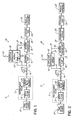
- a water purification system 10 for producing high-purity product water includes a pretreatment (PT) stage 12, a pressure regulator 14, a booster pump 16, a reverse osmosis (RO) unit 18, a capacitive deionization (CDI) module 20, and a drain 22, which are collectively coupled in fluid communication.
- a stream of feed water is provided from a feed water source 24 to the PT stage 12 and a stream of purified product water is transferred to a storage tank 26.
- the storage tank 26 serves as a reservoir for receiving and holding the high-purity product water produced by the water purification system 10.
- a product dispenser 28 such as a tap or a faucet, is used to dispense the purified product water from the storage tank 26.
- the PT stage 12 is operative for removing particulate matter, organic compounds, and free chlorine and other halogens.
- PT stage 12 typically consists of depth filtering with a depth filter 30 and filtering with an activated carbon filter element 32.
- the depth filter 30 incorporates a tortuous, random matrix of small fibers, such as cotton, cellulose, synthetic yarns, or meltblown polymer fibers, through which the feed water supplied from feed water source 24 passes and upon which particulate matter suspended in the feed water is captured.
- the activated carbon filter element 32 removes organic compounds and free chlorine and other halogens from the feed water stream.
- the pressure regulator 14 is positioned in a fluid line 33 coupling the PT stage 12 in fluid communication with a feed water inlet 31 of the RO unit 18 for reducing the feed pressure of the filtrate stream exiting the PT stage 12.
- the booster pump 16 also positioned in the fluid line 33 coupling the PT stage 12 with the feed water inlet 31 of RO unit 18, elevates the water pressure of the filtrate stream exiting the PT stage 12 to a suitable operating pressure so as to provide an adequate driving force for the operation of the RO unit 18.
- the operating pressure is in the range of about 60 psig to about 1000 psig.
- the invention contemplates that the RO unit 18 may comprise a single RO element, multiple RO elements coupled in parallel for fluid communication, or multiple RO elements coupled in series for fluid communication.
- Each RO element of RO unit 18 includes a thin semipermeable membrane operative for removing dissolved ions, typically in the form of dissolved salts, from the filtrate stream received from the PT stage 12.
- a permeate stream is created from the portion of the filtrate stream that penetrates the membrane of each RO element in the RO unit 18.
- a concentrate stream, in which the concentrated dissolved ions rejected by the membrane of RO unit 18 are entrained, is formed by the remainder of the filtrate stream that exits the RO unit 18.
- the RO unit 18 removes most of the dissolved ions and dissolved organic matter from the filtrate stream.
- the RO unit 18 is effective for removing more than about 95 percent of the dissolved organic matter from the filtrate stream and for reducing the concentration of dissolved ions by a factor of about 10 to 20 from the filtrate stream so that the permeate stream is high-purity product water.
- the RO unit 18 has a permeate outlet 34 coupled in fluid communication by a fluid line 35 with the storage tank 26 for directing the permeate stream to the storage tank 26, which collects the high-purity water for subsequent dispensing from product dispenser 28.
- the RO unit 18 also has a concentrate outlet 36 coupled in fluid communication by a fluid line 37 with the CDI module 20 so that the concentrate stream is directed to an inlet 38 of the CDI module 20.
- the permeate stream constitutes about 15 percent by volume of the filtrate stream received from the PT stage 12 and the concentrate stream constitutes about 85 percent by volume of the filtrate stream received from the PT stage 12.
- the CDI module 20 is incorporated in a recirculation path, generally indicated by reference numeral 40, that recycles the concentrate stream back to the feed water inlet 31 of the RO unit 18.
- the inlet 38 of the CDI module 20 receives the concentrate stream, which would otherwise have been sent in a conventional water purification system to drain 22.
- the CDI module 20 operates to further remove residual dissolved ions in the concentrate stream to provide an output stream significantly depleted of dissolved ions.
- the output stream is directed by a fluid line 41 from an outlet 42 of the CDI module 20 to fluid line 33 downstream of pressure regulator 14 and upstream of the feed water inlet 31 of the RO unit 18. It follows that the output stream from the CDI module 20 is blended or combined with the filtrate stream from the PT stage 12 and reenters the RO unit 18.
- 'Recirculation path 40 generally includes fluid lines 37 and 41.
- the CDI module 20 includes a plurality of electrochemical capacitive deionization cells each consisting of spaced-apart pairs of electrodes 43, each of which operates as a flow-through capacitor to provide an electrochemical cell.
- the electrodes 43 are formed of porous conductive material having a high specific surface area, including high-specific-surface-area active carbon structures such as sheets formed of carbon aerogel.
- Each electrochemical cell of the CDI module 20 is polarized by applying an electrical potential to the electrodes 43.
- the CDI module 20 operates cyclically with a purification mode and a regeneration mode.
- dissolved ions arriving in the concentrate stream from the RO unit 18 are held or trapped electrostatically at the surfaces of the charged electrodes 43.
- the CDI module 20 has a certain charging capacity for holding dissolved ions that, when reached, requires that the CDI module be regenerated to flush the trapped dissolved ions to drain 22.
- the regeneration mode the concentrate stream flowing through the CDI module 20 is directed to the drain 22 and the electrochemical cells of CDI module 20 are regenerated or rejuvenated by reversing the polarity of the applied electrical potential to electrodes 43 for a flushing cycle of sufficient duration to desorb substantially all of the trapped dissolved ions into the concentrate stream.
- the production of purified product water may be discontinued when the CDI module 20 is regenerating.
- 25 volumes of water are sent to drain 22 in the regeneration mode for every 75 volumes of water purified by the CDI module 20 and returned to the inlet of the RO unit 18.
- the amount of water directed to drain 22 is significantly reduced by the introduction of the recirculation path 40 having the CDI module 20 than would otherwise be sent to the drain 22 by the output of the RO unit 18. Therefore, the presence of the CDI module 20 significantly reduces the volume of wasted water sent to drain 22, which reduces the operating expense associated with generating the purified product water.
- the CDI module 20 may be any module suitable for performing capacitive deionization that removes dissolved ions from a water stream.
- Exemplary CDI modules 20 for use in the invention are disclosed in U.S. Patent Nos. 6,413,409, 6,346,187 and 6,325,907, the disclosure of each of which is hereby incorporated by reference herein in its entirety.
- the incorporation of the CDI module 20 and recirculation path 40 also increases the purity of the purified product water in the permeate stream because the CDI module 20 operates for removing a significant fraction of the residual dissolved ions in the concentrate stream that remain after treatment by the RO unit 18.
- the CDI module 20 When operating in the purification mode, the CDI module 20 typically removes about 90 percent of the ions in the concentrate stream.
- the water entering the feed water inlet 31 of the RO unit 18 is depleted of dissolved ions by approximately 80 percent as compared with a conventional purification system lacking the recirculation path and CDI module 20.
- the recirculation path 40 and CDI module 20 improve the removal of dissolved ions in the permeate stream exiting the RO unit 18 by a factor of about 5.
- reagent concentrations prepared using the purified product water from the water purification system 10 are more likely to be assured. Water is also conserved by significantly reducing the volume sent to the drain 22.
- a stream of feed water is provided to the PT stage 12 from the feed water source 24.
- the depth filter 30 of PT stage 12 captures particulate matter suspended in the feed water and the activated carbon filter element 32 of PT stage 12 removes large organic compounds and free chlorine from the stream of feed water.
- the outlet pressure of the filtrate stream exiting the PT stage 12 is reduced by pressure regulator 14 and directed to the feed water inlet 31 of the RO unit 18.
- the pressure of the filtrate stream is then boosted by booster pump 16 to an operating pressure suitable for the RO unit 18.
- the RO element of the RO unit 18 removes dissolved ions and dissolved organic matters from the filtrate stream arriving from the PT stage 12, as boosted in pressure by the booster pump 16.
- the permeate stream from the RO unit 18 is directed to storage tank 26 for storage as purified product water that is subsequently dispensed from product dispenser 28.
- the CDI module 20 receives the concentrate stream arriving from the RO unit 18 and electrostatically traps residual dissolved ions in the concentrate stream at the surfaces of its charged electrodes when operating in the purification mode.
- the output stream from the CDI module 20 is directed to the feed water inlet 31 of the RO unit 18, wherein the output stream, highly depleted of dissolved ions, is admixed with the filtrate stream arriving from PT stage 12. The mixture of the filtrate stream and output stream enters the feed water inlet 31 of the RO unit 18.
- water purification system 10 may further include a secondary purification element, such as deionization (DI) module 50, positioned in the fluid path between the RO unit 18 and the storage tank 26, or generally downstream from the water purification system 10.
- DI module 50 contains an ion exchange resin bed containing a material having functional groups capable of removing ions. Permeate emitted from the permeate outlet 34 from RO unit 18 enters an inlet of DI module 50 and, after this purification step, is exhausted to the storage tank 26.
- the permeate from the RO unit 18 may be further purified by other types of purification technologies, such as an electrodeionization (EDI) module (not shown), that also incorporates an ion exchange resin bed.
- EDI electrodeionization
- the significant reduction in the ion concentration in the permeate exiting the RO unit 18, according to the principles of the invention, has the benefit of reducing the operating cost for downstream purification systems, such as DI module 50, that further purify the permeate using an ion exchange resin bed.
- DI module 50 that further purify the permeate using an ion exchange resin bed.
- the frequency of regenerating the ion exchange resin bed is reduced which lowers the requisite volume of caustic chemicals and decreases the volume of the waste stream of spent caustic chemicals.
- Water purification system 10 also eliminates the need for a water softening process upstream of the RO unit 18 before any downstream EDI modules (not shown) receive the permeate stream. As a result, such downstream EDI modules are less likely to be compromised by scaling and a water softener is not required for pretreating the filtrate provided to the RO unit 18.
- the storage tank 26 of the water purification system 10 may further include a recirculation path, indicated generally by reference numeral 52.
- the recirculation path 52 includes an ultraviolet (UV) light treatment unit 54 and a deionization (DI) module 56 similar to DI module 50.
- UV ultraviolet
- DI deionization
- High-purity product water is pumped from storage tank 26 by a transfer pump 58 through the UV light treatment unit 54 and the DI module 56 and is returned to the storage tank 26.
- the UV light treatment unit 54 disinfects or sterilizes the high-purity product water held in the storage tank 26 so as to restrict bacterial growth and removes total organic carbon (TOC) from the high-purity product water.
- TOC total organic carbon
- a water purification system 60 may include a recirculation path 62 equipped with a pair of CDI modules 64, 66.
- An additional carbon filter element 68 similar to carbon filter element 32, is provided in the fluid line 33 between the pressure regulator 14 and the booster pump 16.
- the water purification system 60 may be equipped with conductivity cells 63, 65 at various points in the flow pathway for monitoring the water conductivity, which is indicative of the residual concentration of dissolved ions.
- An inlet 70 of CDI module 64 and an inlet 69 of CDI module 66 are collectively coupled in fluid communication by a fluid line 71 with the concentrate outlet 36 of the RO unit 18 in a duplex arrangement.
- An outlet 72 of CDI module 64 is coupled in fluid communication by a fluid line 73 with an inlet 74 of a three-way fitting 75 having one outlet 76 selectively coupled in fluid communication with fluid line 77 to permit flow to fluid line 33 for closing recirculation path 62 returning water to the feed water inlet 31 of RO unit 18 during purification mode.
- Another outlet 78 of the three-way fitting 75 is selectively coupled in fluid communication by a fluid line 80 with a flow path to drain 22 for permitting flow to drain 22 during regeneration mode.
- an outlet 82 of CDI module 66 is coupled in fluid communication by a fluid line 81 with an inlet 84 of a three-way fitting 83 having one outlet 86 selectively coupled in fluid communication with fluid line 77 to permit flow to fluid line 33 for closing recirculation path 62 returning water to the feed water inlet 31 of RO unit 18 during purification mode.
- Another outlet 88 of the three-way fitting 83 is selectively coupled in fluid communication by fluid line 80 with a flow path to drain 22 for permitting flow to drain 22 during regeneration mode.
- a flow restrictor 90 is positioned in the flow path, provided partially by fluid line 80, between the outlets 78, 88 and the drain 22.
- one of the CDI modules for example, CDI module 64
- one of the CDI modules operates in its purification mode to produce an output stream directed by three-way fitting 75 from outlet 72 through fluid line 77 to the feed water inlet 31 of the RO unit 18 while the other of the CDI modules, for example, CDI module 66, is operating in its regeneration mode with its output stream diverted from outlet 82 by three-way fitting 83 through fluid line 80 to the drain 22.
- Such an operation of the CDI modules 64, 66 continuously generates purified product water without interruption.
- purified product water is continuously dispensed as at least one of outlet 72 of CDI module 64 or outlet 82 of CDI module 66 is alternatingly in fluid communication with the feed water inlet 31 of RO unit 18.
- both of the outlets 72 and 82 may simultaneously coupled in fluid communication with the feed water inlet 31 of the RO unit 18. This would occur, for example, if the flushing cycle of, for example, CDI module 64 concludes while CDI module 66 is operating in purification mode and its charging capacity has not been exceeded.
- the three-way fitting 83 may be switched so that the output stream from outlet 82 is directed through outlet 86 to the feed water inlet 31 of the RO unit 18.
- the permeate stream from the RO unit 18 is diverted in a recirculation path, generally indicated by reference numeral 92, coupling the permeate outlet 34 with fluid line 33 upstream of the feed water inlet 31 to the RO unit 18, and the water purification system 60 is isolated from the feed water source 24 so that feed water does not enter system 60.
- the permeate stream admixes with the output stream from the CDI module 20, which are collectively directed to the feed water inlet 31 of the RO unit 18.
- the recirculation in the batch mode of operation continuously removes dissolved ions from the water to incrementally increase the water purity. Recirculation through the recirculation path 92 may be discontinued when a desired water purity is achieved.
- the recirculation path 92 is selectively coupled by a three-way fitting 93 in fluid communication with the fluid line 37 carrying the permeate stream exiting the RO unit 18.
- An inlet 95 of the three-way fitting 93 receives the permeate stream, which may be directed to the storage tank 26 via outlet 97.
- the recirculation path 92 includes a fluid line 96 coupling an outlet 98 of three-way fitting 93 with an inlet 99 of a three-way fitting 100.
- One outlet 102 of three-way fitting 100 is selectively coupled in fluid communication with a product dispenser 104.
- Another outlet 106 of three-way fitting 100 is selectively coupled by fluid line 108 in fluid communication with fluid line 33 upstream of the inlet to the RO unit 18.
- the three-way fitting 93 is adjusted to direct permeate water received from the RO unit 18 through outlet 98 to fluid line 96 of recirculation path 92.
- the permeate water flowing in fluid line 96 may diverted by three-way fitting 100 either through outlet 102 to product dispenser 104 or through outlet 106 to fluid line 108 for recirculation to fluid line 33 upstream of the feed water inlet 31 of RO unit 18.
- additional feed water may be introduced from the feed water source 24 as needed for maintaining a constant water volume in system 60.
Landscapes
- Chemical & Material Sciences (AREA)
- Engineering & Computer Science (AREA)
- Water Supply & Treatment (AREA)
- Chemical Kinetics & Catalysis (AREA)
- Life Sciences & Earth Sciences (AREA)
- Environmental & Geological Engineering (AREA)
- Hydrology & Water Resources (AREA)
- Nanotechnology (AREA)
- Organic Chemistry (AREA)
- Health & Medical Sciences (AREA)
- Analytical Chemistry (AREA)
- Molecular Biology (AREA)
- Electrochemistry (AREA)
- General Chemical & Material Sciences (AREA)
- Separation Using Semi-Permeable Membranes (AREA)
- Water Treatment By Electricity Or Magnetism (AREA)
Applications Claiming Priority (2)
| Application Number | Priority Date | Filing Date | Title |
|---|---|---|---|
| US10/324,214 US20040118780A1 (en) | 2002-12-20 | 2002-12-20 | Water purification system and method |
| US324214 | 2002-12-20 |
Publications (3)
| Publication Number | Publication Date |
|---|---|
| EP1431250A2 true EP1431250A2 (fr) | 2004-06-23 |
| EP1431250A3 EP1431250A3 (fr) | 2004-08-04 |
| EP1431250B1 EP1431250B1 (fr) | 2005-11-16 |
Family
ID=32393057
Family Applications (1)
| Application Number | Title | Priority Date | Filing Date |
|---|---|---|---|
| EP03257465A Expired - Lifetime EP1431250B1 (fr) | 2002-12-20 | 2003-11-26 | Système et procédé de purification de l'eau |
Country Status (3)
| Country | Link |
|---|---|
| US (1) | US20040118780A1 (fr) |
| EP (1) | EP1431250B1 (fr) |
| DE (1) | DE60302319T2 (fr) |
Cited By (10)
| Publication number | Priority date | Publication date | Assignee | Title |
|---|---|---|---|---|
| EP1803689A1 (fr) * | 2005-12-29 | 2007-07-04 | Ansaldo Energia S.P.A. | Système de traitement des eaux usées industrielles, en particulier d'une installation de production d'énergie |
| CN101977670A (zh) * | 2008-01-28 | 2011-02-16 | 爱惠浦有限责任公司 | 反渗透系统 |
| EP2423169A1 (fr) * | 2010-08-27 | 2012-02-29 | Manfred Völker | Installation comprenent des unités d'osmose inversé et adoucisseur pour produire de i'eau ultrapure |
| CN102656121A (zh) * | 2009-07-21 | 2012-09-05 | 林德股份公司 | 一种净化工艺冷凝液的方法 |
| CN103359866A (zh) * | 2013-07-23 | 2013-10-23 | 南京工业大学 | 一种净化水水质平衡方法 |
| EP2397209A4 (fr) * | 2009-02-16 | 2013-10-30 | Kuraray Co | Dispositif de filtration et son procédé de fabrication |
| US9702124B2 (en) | 2007-11-07 | 2017-07-11 | Georg Fischer Llc | High purity water system |
| WO2018019005A1 (fr) * | 2016-07-26 | 2018-02-01 | 吴达镕 | Système de filtration de source d'eau de secours |
| US10246351B2 (en) | 2011-09-24 | 2019-04-02 | Vivonic Gmbh | Device for producing ultrapure water |
| WO2019115490A1 (fr) * | 2017-12-14 | 2019-06-20 | Merck Patent Gmbh | Système de purification et de distribution d'eau et procédé de fonctionnement d'un tel système |
Families Citing this family (27)
| Publication number | Priority date | Publication date | Assignee | Title |
|---|---|---|---|---|
| US20050103717A1 (en) | 2003-11-13 | 2005-05-19 | United States Filter Corporation | Water treatment system and method |
| US7846340B2 (en) * | 2003-11-13 | 2010-12-07 | Siemens Water Technologies Corp. | Water treatment system and method |
| US7083733B2 (en) | 2003-11-13 | 2006-08-01 | Usfilter Corporation | Water treatment system and method |
| US8377279B2 (en) | 2003-11-13 | 2013-02-19 | Siemens Industry, Inc. | Water treatment system and method |
| US20080067069A1 (en) | 2006-06-22 | 2008-03-20 | Siemens Water Technologies Corp. | Low scale potential water treatment |
| RU2009128193A (ru) * | 2006-12-22 | 2011-01-27 | Сименс Уотер Текнолоджиз Корп. (Us) | Устройства и способы обработки технологического потока |
| MX2010005876A (es) | 2007-11-30 | 2010-06-15 | Siemens Water Tech Corp | Sistemas y metodos para tratamiento de agua. |
| DE102008052001A1 (de) * | 2008-10-16 | 2010-04-29 | Krones Ag | Verfahren zur Wasserbehandlung |
| DE102011017455A1 (de) * | 2011-04-18 | 2012-10-18 | Roland de Craigher | Verfahren und Vorrichtung zur physikalischen Trinkwasserreinigung |
| WO2013040420A2 (fr) * | 2011-09-15 | 2013-03-21 | Deka Products Limited Partnership | Systèmes, appareil et procédés destinés à un système d'épuration des eaux |
| CN103011479A (zh) * | 2011-09-22 | 2013-04-03 | 陈明初 | 多功能ro制水机及其制备方法 |
| US9695070B2 (en) | 2011-10-27 | 2017-07-04 | Pentair Residential Filtration, Llc | Regeneration of a capacitive deionization system |
| US9637397B2 (en) | 2011-10-27 | 2017-05-02 | Pentair Residential Filtration, Llc | Ion removal using a capacitive deionization system |
| US9010361B2 (en) | 2011-10-27 | 2015-04-21 | Pentair Residential Filtration, Llc | Control valve assembly |
| US8961770B2 (en) | 2011-10-27 | 2015-02-24 | Pentair Residential Filtration, Llc | Controller and method of operation of a capacitive deionization system |
| US8671985B2 (en) | 2011-10-27 | 2014-03-18 | Pentair Residential Filtration, Llc | Control valve assembly |
| US9475717B2 (en) | 2012-08-23 | 2016-10-25 | Total Water Treatment Systems, Inc. | Water purification system engineered for legionella control in industrial and commercial water systems |
| EP3119725B1 (fr) * | 2014-03-19 | 2019-10-16 | University Of South Florida | Systèmes portatifs de traitement des eaux usées |
| KR101529477B1 (ko) * | 2014-06-30 | 2015-06-29 | 주식회사 한화건설 | Cdi를 이용한 나노 역삼투 막여과 공정 |
| US10968117B2 (en) * | 2015-04-14 | 2021-04-06 | Koninklijke Philips N.V. | Electrosorption purification system with recirculation |
| KR101636701B1 (ko) * | 2015-06-04 | 2016-07-07 | 주식회사 한화건설 | Cdi를 이용한 나노 역삼투 막여과 공정 |
| GB201617347D0 (en) * | 2016-10-13 | 2016-11-30 | VWS (UK) Limited | Method and apparatus for providing ultrapure water |
| US20230128055A1 (en) * | 2019-03-07 | 2023-04-27 | Kyungdong Navien Co., Ltd. | Water-softening system |
| CN111115771B (zh) * | 2020-02-27 | 2024-05-14 | 佛山市顺德区美的饮水机制造有限公司 | 水路系统和净水设备 |
| JP7297312B2 (ja) * | 2020-06-19 | 2023-06-26 | ゼオライト株式会社 | 浴場排水浄化装置 |
| CN113666564A (zh) * | 2021-09-15 | 2021-11-19 | 北京国电富通科技发展有限责任公司 | 一种换流站外排水处理系统 |
| EP4393891A1 (fr) * | 2022-12-30 | 2024-07-03 | Thermo Orion Inc. | Appareil et procédé de réduction de carbone organique total dans un fluide |
Family Cites Families (31)
| Publication number | Priority date | Publication date | Assignee | Title |
|---|---|---|---|---|
| US4332685A (en) * | 1978-01-26 | 1982-06-01 | Ecodyne Corporation | Method and apparatus for treating water |
| US4276177A (en) * | 1979-08-13 | 1981-06-30 | Vaponics Inc. | High efficiency filtration with impurity concentration and ultrafiltration rejection flow recirculation |
| JPS6161689A (ja) * | 1984-08-31 | 1986-03-29 | Hitachi Ltd | 純水製造装置 |
| US4595498A (en) * | 1984-12-27 | 1986-06-17 | Thomson Components-Mostek Corporation | Water-polishing loop |
| US5620597A (en) * | 1990-04-23 | 1997-04-15 | Andelman; Marc D. | Non-fouling flow-through capacitor |
| US5192432A (en) * | 1990-04-23 | 1993-03-09 | Andelman Marc D | Flow-through capacitor |
| US5196115A (en) * | 1990-04-23 | 1993-03-23 | Andelman Marc D | Controlled charge chromatography system |
| US5200068A (en) * | 1990-04-23 | 1993-04-06 | Andelman Marc D | Controlled charge chromatography system |
| US5360540A (en) * | 1990-04-23 | 1994-11-01 | Andelman Marc D | Chromatography system |
| US5415768A (en) * | 1990-04-23 | 1995-05-16 | Andelman; Marc D. | Flow-through capacitor |
| US5538611A (en) * | 1993-05-17 | 1996-07-23 | Marc D. Andelman | Planar, flow-through, electric, double-layer capacitor and a method of treating liquids with the capacitor |
| US6110375A (en) * | 1994-01-11 | 2000-08-29 | Millipore Corporation | Process for purifying water |
| US5503729A (en) * | 1994-04-25 | 1996-04-02 | Ionics Incorporated | Electrodialysis including filled cell electrodialysis (electrodeionization) |
| US6309532B1 (en) * | 1994-05-20 | 2001-10-30 | Regents Of The University Of California | Method and apparatus for capacitive deionization and electrochemical purification and regeneration of electrodes |
| US5425858A (en) * | 1994-05-20 | 1995-06-20 | The Regents Of The University Of California | Method and apparatus for capacitive deionization, electrochemical purification, and regeneration of electrodes |
| US5585531A (en) * | 1994-10-07 | 1996-12-17 | Barker; Tracy A. | Method for processing liquid radioactive waste |
| CA2197525A1 (fr) * | 1996-02-14 | 1997-08-15 | Mahabala R. Adiga | Traitement des eaux usees d'une usine de placage metallique et methode d'extraction des metaux |
| JP2887105B2 (ja) * | 1996-04-24 | 1999-04-26 | 幸子 林 | 飲料水および塩の製造方法および製造装置 |
| CA2186963C (fr) * | 1996-10-01 | 1999-03-30 | Riad A. Al-Samadi | Procede de purification par osmose inverse a rendement eleve |
| US5925230A (en) * | 1997-10-06 | 1999-07-20 | Southeastern Trading, Llp | Deionization apparatus having non-sacrificial electrodes of different types |
| US5980718A (en) * | 1998-05-04 | 1999-11-09 | The Regents Of The University Of California | Means for limiting and ameliorating electrode shorting |
| US6413409B1 (en) * | 1998-09-08 | 2002-07-02 | Biosource, Inc. | Flow-through capacitor and method of treating liquids with it |
| US6389414B1 (en) * | 1998-09-21 | 2002-05-14 | Microsoft Corporation | Internal database validation |
| US6187197B1 (en) * | 1998-10-28 | 2001-02-13 | Marvin Haddock | Multi-stage engine coolant recycling process |
| US6346187B1 (en) * | 1999-01-21 | 2002-02-12 | The Regents Of The University Of California | Alternating-polarity operation for complete regeneration of electrochemical deionization system |
| US6778378B1 (en) * | 1999-07-30 | 2004-08-17 | Biosource, Inc. | Flow-through capacitor and method |
| JP3570304B2 (ja) * | 1999-08-11 | 2004-09-29 | 栗田工業株式会社 | 脱イオン水製造装置の殺菌方法及び脱イオン水の製造方法 |
| US6325907B1 (en) * | 1999-10-18 | 2001-12-04 | Marc D. Andelman | Energy and weight efficient flow-through capacitor, system and method |
| US6410128B1 (en) * | 2000-03-13 | 2002-06-25 | Graftech Inc. | Flexible graphite capacitor element |
| US6580598B2 (en) * | 2001-02-15 | 2003-06-17 | Luxon Energy Devices Corporation | Deionizers with energy recovery |
| US6462935B1 (en) * | 2001-09-07 | 2002-10-08 | Lih-Ren Shiue | Replaceable flow-through capacitors for removing charged species from liquids |
-
2002
- 2002-12-20 US US10/324,214 patent/US20040118780A1/en not_active Abandoned
-
2003
- 2003-11-26 EP EP03257465A patent/EP1431250B1/fr not_active Expired - Lifetime
- 2003-11-26 DE DE60302319T patent/DE60302319T2/de not_active Expired - Lifetime
Cited By (17)
| Publication number | Priority date | Publication date | Assignee | Title |
|---|---|---|---|---|
| EP1803689A1 (fr) * | 2005-12-29 | 2007-07-04 | Ansaldo Energia S.P.A. | Système de traitement des eaux usées industrielles, en particulier d'une installation de production d'énergie |
| US9702124B2 (en) | 2007-11-07 | 2017-07-11 | Georg Fischer Llc | High purity water system |
| CN101977670A (zh) * | 2008-01-28 | 2011-02-16 | 爱惠浦有限责任公司 | 反渗透系统 |
| CN101977670B (zh) * | 2008-01-28 | 2014-09-10 | 爱惠浦有限责任公司 | 反渗透系统 |
| EP2397209A4 (fr) * | 2009-02-16 | 2013-10-30 | Kuraray Co | Dispositif de filtration et son procédé de fabrication |
| US9050563B2 (en) | 2009-02-16 | 2015-06-09 | Kuraray Co., Ltd. | Filtering device and method of manufacturing same |
| CN102656121A (zh) * | 2009-07-21 | 2012-09-05 | 林德股份公司 | 一种净化工艺冷凝液的方法 |
| EP2423169A1 (fr) * | 2010-08-27 | 2012-02-29 | Manfred Völker | Installation comprenent des unités d'osmose inversé et adoucisseur pour produire de i'eau ultrapure |
| US9011682B2 (en) | 2010-08-27 | 2015-04-21 | Manfred Volker | Reverse osmosis device |
| US10246351B2 (en) | 2011-09-24 | 2019-04-02 | Vivonic Gmbh | Device for producing ultrapure water |
| CN103359866B (zh) * | 2013-07-23 | 2015-10-28 | 南京工业大学 | 一种净化水水质平衡方法 |
| CN103359866A (zh) * | 2013-07-23 | 2013-10-23 | 南京工业大学 | 一种净化水水质平衡方法 |
| WO2018019005A1 (fr) * | 2016-07-26 | 2018-02-01 | 吴达镕 | Système de filtration de source d'eau de secours |
| WO2019115490A1 (fr) * | 2017-12-14 | 2019-06-20 | Merck Patent Gmbh | Système de purification et de distribution d'eau et procédé de fonctionnement d'un tel système |
| CN111479781A (zh) * | 2017-12-14 | 2020-07-31 | 默克专利股份公司 | 水净化和施配系统以及操作这种系统的方法 |
| US11390548B2 (en) | 2017-12-14 | 2022-07-19 | Merck Patent Gmbh | Water purification and dispensing system and method of operating such system |
| CN111479781B (zh) * | 2017-12-14 | 2023-02-17 | 默克专利股份公司 | 水净化和施配系统以及操作这种系统的方法 |
Also Published As
| Publication number | Publication date |
|---|---|
| EP1431250A3 (fr) | 2004-08-04 |
| US20040118780A1 (en) | 2004-06-24 |
| EP1431250B1 (fr) | 2005-11-16 |
| DE60302319T2 (de) | 2006-07-13 |
| DE60302319D1 (de) | 2005-12-22 |
Similar Documents
| Publication | Publication Date | Title |
|---|---|---|
| EP1431250B1 (fr) | Système et procédé de purification de l'eau | |
| AU2005302508B2 (en) | EDI concentrate recycle loop with filtration module | |
| JP3244689B2 (ja) | 水を浄化するための電気脱イオン化及び紫外線処理方法 | |
| US7582198B2 (en) | Water treatment system and method | |
| EP3526169B1 (fr) | Procédé et appareil de fourniture d'eau ultra-pure | |
| KR100361799B1 (ko) | 포토레지스트현상폐액의재생처리방법및장치 | |
| US12263446B2 (en) | Electrodialysis process and bipolar membrane electrodialysis devices for silica removal | |
| JP2002509802A (ja) | 水処理システム及びpH調節を含む水処理法 | |
| GB2249307A (en) | Process for purifying water by means of a combination of electrodialysis and reverse osmosis | |
| KR20190061523A (ko) | 농축수 저감형 전기흡착 탈염 시스템 | |
| US6998044B2 (en) | Electrophoretic cross-flow filtration and electrodeionization: method for treating effluent waste and apparatus for use therewith | |
| US20060254919A1 (en) | Electrophoretic cross-flow filtration and electrodeionization method for treating effluent waste and apparatus for use therewith | |
| CN107098526A (zh) | 浓盐水零排放分质结晶的膜浓缩设备及处理工艺 | |
| EP1685070B1 (fr) | Systeme et procede de traitement de l'eau | |
| CN211972026U (zh) | 实验室用超纯水制备系统 | |
| MXPA06005384A (en) | Water treatment system and method | |
| KR102703647B1 (ko) | Tmah가 함유된 폐수의 처리 및 재이용 시스템 | |
| KR100345725B1 (ko) | 역삼투와나노필터시스템을이용한폐수처리방법 | |
| CN206529377U (zh) | 一种高盐高cod废水处理与资源回收装置 | |
| KR20260039334A (ko) | 스택 라디에이터 무이온 세척기 | |
| CN119612812A (zh) | 一种电子级超纯水制备系统及工艺 | |
| IL302180A (en) | Electroionization configuration for accelerated removal of weakly ionized species | |
| JP2002028660A (ja) | 脱塩装置 | |
| CN112495186A (zh) | 二级ro浓水至超滤产工艺 |
Legal Events
| Date | Code | Title | Description |
|---|---|---|---|
| PUAI | Public reference made under article 153(3) epc to a published international application that has entered the european phase |
Free format text: ORIGINAL CODE: 0009012 |
|
| PUAL | Search report despatched |
Free format text: ORIGINAL CODE: 0009013 |
|
| AK | Designated contracting states |
Kind code of ref document: A2 Designated state(s): AT BE BG CH CY CZ DE DK EE ES FI FR GB GR HU IE IT LI LU MC NL PT RO SE SI SK TR |
|
| AX | Request for extension of the european patent |
Extension state: AL LT LV MK |
|
| AK | Designated contracting states |
Kind code of ref document: A3 Designated state(s): AT BE BG CH CY CZ DE DK EE ES FI FR GB GR HU IE IT LI LU MC NL PT RO SE SI SK TR |
|
| AX | Request for extension of the european patent |
Extension state: AL LT LV MK |
|
| GRAP | Despatch of communication of intention to grant a patent |
Free format text: ORIGINAL CODE: EPIDOSNIGR1 |
|
| 17P | Request for examination filed |
Effective date: 20041008 |
|
| GRAS | Grant fee paid |
Free format text: ORIGINAL CODE: EPIDOSNIGR3 |
|
| AKX | Designation fees paid |
Designated state(s): DE FR GB |
|
| GRAA | (expected) grant |
Free format text: ORIGINAL CODE: 0009210 |
|
| AK | Designated contracting states |
Kind code of ref document: B1 Designated state(s): DE FR GB |
|
| REG | Reference to a national code |
Ref country code: GB Ref legal event code: FG4D |
|
| REF | Corresponds to: |
Ref document number: 60302319 Country of ref document: DE Date of ref document: 20051222 Kind code of ref document: P |
|
| ET | Fr: translation filed | ||
| PLBE | No opposition filed within time limit |
Free format text: ORIGINAL CODE: 0009261 |
|
| STAA | Information on the status of an ep patent application or granted ep patent |
Free format text: STATUS: NO OPPOSITION FILED WITHIN TIME LIMIT |
|
| 26N | No opposition filed |
Effective date: 20060817 |
|
| PGFP | Annual fee paid to national office [announced via postgrant information from national office to epo] |
Ref country code: FR Payment date: 20091123 Year of fee payment: 7 Ref country code: GB Payment date: 20091125 Year of fee payment: 7 |
|
| PGFP | Annual fee paid to national office [announced via postgrant information from national office to epo] |
Ref country code: DE Payment date: 20101124 Year of fee payment: 8 |
|
| GBPC | Gb: european patent ceased through non-payment of renewal fee |
Effective date: 20101126 |
|
| REG | Reference to a national code |
Ref country code: FR Ref legal event code: ST Effective date: 20110801 |
|
| PG25 | Lapsed in a contracting state [announced via postgrant information from national office to epo] |
Ref country code: FR Free format text: LAPSE BECAUSE OF NON-PAYMENT OF DUE FEES Effective date: 20101130 |
|
| PG25 | Lapsed in a contracting state [announced via postgrant information from national office to epo] |
Ref country code: GB Free format text: LAPSE BECAUSE OF NON-PAYMENT OF DUE FEES Effective date: 20101126 |
|
| REG | Reference to a national code |
Ref country code: DE Ref legal event code: R119 Ref document number: 60302319 Country of ref document: DE Effective date: 20130601 |
|
| PG25 | Lapsed in a contracting state [announced via postgrant information from national office to epo] |
Ref country code: DE Free format text: LAPSE BECAUSE OF NON-PAYMENT OF DUE FEES Effective date: 20130601 |