EP1431495A2 - Entraínement électrohydraulique pour porte pivotante - Google Patents
Entraínement électrohydraulique pour porte pivotante Download PDFInfo
- Publication number
- EP1431495A2 EP1431495A2 EP03029121A EP03029121A EP1431495A2 EP 1431495 A2 EP1431495 A2 EP 1431495A2 EP 03029121 A EP03029121 A EP 03029121A EP 03029121 A EP03029121 A EP 03029121A EP 1431495 A2 EP1431495 A2 EP 1431495A2
- Authority
- EP
- European Patent Office
- Prior art keywords
- valve
- swing door
- door drive
- hydraulic
- electro
- Prior art date
- Legal status (The legal status is an assumption and is not a legal conclusion. Google has not performed a legal analysis and makes no representation as to the accuracy of the status listed.)
- Withdrawn
Links
Images



Classifications
-
- E—FIXED CONSTRUCTIONS
- E05—LOCKS; KEYS; WINDOW OR DOOR FITTINGS; SAFES
- E05F—DEVICES FOR MOVING WINGS INTO OPEN OR CLOSED POSITION; CHECKS FOR WINGS; WING FITTINGS NOT OTHERWISE PROVIDED FOR, CONCERNED WITH THE FUNCTIONING OF THE WING
- E05F3/00—Closers or openers with braking devices, e.g. checks; Construction of pneumatic or liquid braking devices
- E05F3/22—Additional arrangements for closers, e.g. for holding the wing in opened or other position
- E05F3/224—Additional arrangements for closers, e.g. for holding the wing in opened or other position for assisting in opening the wing
-
- E—FIXED CONSTRUCTIONS
- E05—LOCKS; KEYS; WINDOW OR DOOR FITTINGS; SAFES
- E05F—DEVICES FOR MOVING WINGS INTO OPEN OR CLOSED POSITION; CHECKS FOR WINGS; WING FITTINGS NOT OTHERWISE PROVIDED FOR, CONCERNED WITH THE FUNCTIONING OF THE WING
- E05F3/00—Closers or openers with braking devices, e.g. checks; Construction of pneumatic or liquid braking devices
- E05F3/04—Closers or openers with braking devices, e.g. checks; Construction of pneumatic or liquid braking devices with liquid piston brakes
- E05F3/10—Closers or openers with braking devices, e.g. checks; Construction of pneumatic or liquid braking devices with liquid piston brakes with a spring, other than a torsion spring, and a piston, the axes of which are the same or lie in the same direction
- E05F3/102—Closers or openers with braking devices, e.g. checks; Construction of pneumatic or liquid braking devices with liquid piston brakes with a spring, other than a torsion spring, and a piston, the axes of which are the same or lie in the same direction with rack-and-pinion transmission between driving shaft and piston within the closer housing
-
- E—FIXED CONSTRUCTIONS
- E05—LOCKS; KEYS; WINDOW OR DOOR FITTINGS; SAFES
- E05F—DEVICES FOR MOVING WINGS INTO OPEN OR CLOSED POSITION; CHECKS FOR WINGS; WING FITTINGS NOT OTHERWISE PROVIDED FOR, CONCERNED WITH THE FUNCTIONING OF THE WING
- E05F3/00—Closers or openers with braking devices, e.g. checks; Construction of pneumatic or liquid braking devices
- E05F3/04—Closers or openers with braking devices, e.g. checks; Construction of pneumatic or liquid braking devices with liquid piston brakes
- E05F3/12—Special devices controlling the circulation of the liquid, e.g. valve arrangement
-
- E—FIXED CONSTRUCTIONS
- E05—LOCKS; KEYS; WINDOW OR DOOR FITTINGS; SAFES
- E05F—DEVICES FOR MOVING WINGS INTO OPEN OR CLOSED POSITION; CHECKS FOR WINGS; WING FITTINGS NOT OTHERWISE PROVIDED FOR, CONCERNED WITH THE FUNCTIONING OF THE WING
- E05F3/00—Closers or openers with braking devices, e.g. checks; Construction of pneumatic or liquid braking devices
- E05F3/22—Additional arrangements for closers, e.g. for holding the wing in opened or other position
- E05F3/223—Hydraulic power-locks, e.g. with electrically operated hydraulic valves
-
- E—FIXED CONSTRUCTIONS
- E05—LOCKS; KEYS; WINDOW OR DOOR FITTINGS; SAFES
- E05Y—INDEXING SCHEME ASSOCIATED WITH SUBCLASSES E05D AND E05F, RELATING TO CONSTRUCTION ELEMENTS, ELECTRIC CONTROL, POWER SUPPLY, POWER SIGNAL OR TRANSMISSION, USER INTERFACES, MOUNTING OR COUPLING, DETAILS, ACCESSORIES, AUXILIARY OPERATIONS NOT OTHERWISE PROVIDED FOR, APPLICATION THEREOF
- E05Y2201/00—Constructional elements; Accessories therefor
- E05Y2201/20—Brakes; Disengaging means; Holders; Stops; Valves; Accessories therefor
-
- E—FIXED CONSTRUCTIONS
- E05—LOCKS; KEYS; WINDOW OR DOOR FITTINGS; SAFES
- E05Y—INDEXING SCHEME ASSOCIATED WITH SUBCLASSES E05D AND E05F, RELATING TO CONSTRUCTION ELEMENTS, ELECTRIC CONTROL, POWER SUPPLY, POWER SIGNAL OR TRANSMISSION, USER INTERFACES, MOUNTING OR COUPLING, DETAILS, ACCESSORIES, AUXILIARY OPERATIONS NOT OTHERWISE PROVIDED FOR, APPLICATION THEREOF
- E05Y2201/00—Constructional elements; Accessories therefor
- E05Y2201/20—Brakes; Disengaging means; Holders; Stops; Valves; Accessories therefor
- E05Y2201/252—Type of friction
- E05Y2201/254—Fluid or viscous friction
-
- E—FIXED CONSTRUCTIONS
- E05—LOCKS; KEYS; WINDOW OR DOOR FITTINGS; SAFES
- E05Y—INDEXING SCHEME ASSOCIATED WITH SUBCLASSES E05D AND E05F, RELATING TO CONSTRUCTION ELEMENTS, ELECTRIC CONTROL, POWER SUPPLY, POWER SIGNAL OR TRANSMISSION, USER INTERFACES, MOUNTING OR COUPLING, DETAILS, ACCESSORIES, AUXILIARY OPERATIONS NOT OTHERWISE PROVIDED FOR, APPLICATION THEREOF
- E05Y2400/00—Electronic control; Electrical power; Power supply; Power or signal transmission; User interfaces
- E05Y2400/10—Electronic control
- E05Y2400/30—Electronic control of motors
- E05Y2400/3013—Electronic control of motors during manual wing operation
- E05Y2400/3015—Power assistance
-
- E—FIXED CONSTRUCTIONS
- E05—LOCKS; KEYS; WINDOW OR DOOR FITTINGS; SAFES
- E05Y—INDEXING SCHEME ASSOCIATED WITH SUBCLASSES E05D AND E05F, RELATING TO CONSTRUCTION ELEMENTS, ELECTRIC CONTROL, POWER SUPPLY, POWER SIGNAL OR TRANSMISSION, USER INTERFACES, MOUNTING OR COUPLING, DETAILS, ACCESSORIES, AUXILIARY OPERATIONS NOT OTHERWISE PROVIDED FOR, APPLICATION THEREOF
- E05Y2800/00—Details, accessories and auxiliary operations not otherwise provided for
-
- E—FIXED CONSTRUCTIONS
- E05—LOCKS; KEYS; WINDOW OR DOOR FITTINGS; SAFES
- E05Y—INDEXING SCHEME ASSOCIATED WITH SUBCLASSES E05D AND E05F, RELATING TO CONSTRUCTION ELEMENTS, ELECTRIC CONTROL, POWER SUPPLY, POWER SIGNAL OR TRANSMISSION, USER INTERFACES, MOUNTING OR COUPLING, DETAILS, ACCESSORIES, AUXILIARY OPERATIONS NOT OTHERWISE PROVIDED FOR, APPLICATION THEREOF
- E05Y2900/00—Application of doors, windows, wings or fittings thereof
- E05Y2900/10—Application of doors, windows, wings or fittings thereof for buildings or parts thereof
- E05Y2900/13—Type of wing
- E05Y2900/132—Doors
Definitions
- the invention relates to an electrohydraulic swing door drive an open hold function, the execution of the hold open function in hydraulic circuit arranged a hydraulically controlled hold-open valve is.
- the door can be kept permanently open because only a low control pressure is required, e.g. B. from a motor pump unit for a very long period of time without the risk of overheating, and be maintained with minimal brush burn-up can.
- a low control pressure e.g. B. from a motor pump unit for a very long period of time without the risk of overheating, and be maintained with minimal brush burn-up can.
- the swing door drive according to the invention when switched off Motor works unaffected by the hydraulic drive, so that no additional switching valve is required.
- the fact that the invention Hold valve a 2-2-way valve, a control piston and has a check valve the backflow of hydraulic fluid be prevented from the piston space into a tank space.
- the 2-2-way valve is constructed with a relatively low control pressure a pressure that is several times greater in the piston chamber of the swing door drive can be held.
- the pressure in the piston chamber of the swing door drive by several times greater than the control pressure in the hold-open valve. In this way can be provided with a swing door drive according to the invention Door against the spring force of a spring contained in the swing door operator be kept permanently open.
- a DC motor as an electronically commutated motor or as a speed-controllable alternating or three-phase motor provided motor, which is a pump drives, because only with such engines, the engine torque and engine speed can be changed and a permanent open function with low Power losses can be realized.
- the inflow and the backflow of the hydraulic circuit are preferred separated from each other. This reduces the number of required Valves, but requires an additional hydraulic line.
- check valve in the control piston of the hold-open valve integrated.
- this can Check valve also provided in a bypass to the hold-open valve his.
- Throttle valves are provided.
- the hold-open valve according to the invention is preferably via the Pump pressure controlled.
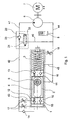
- Figure 1 is a swing door drive according to the invention according to a first Embodiment shown.
- the Closing movement of the swing door drive controlled by throttle valves.
- the swing door drive has a piston chamber 1 in which a piston 2 can be moved against the force of a spring 3.
- the piston 2 is with a Toothing 4 provided, which meshes with a pinion 5, which with a Locking mechanism, not shown, for a door, a window or the like works together.
- the toothing 4 is shown in the Embodiment formed inside the piston 2. As a result of one Movement of the piston 2 is via the toothing 4, the pinion 5 in one Offset rotary movement.
- the piston 2 is driven by a hydraulic circuit, which Hydraulic lines to the piston chamber 1 is connected.
- a pump 6 is provided which is driven by a motor 7 becomes.
- the motor 7 is preferably as a DC motor or as speed-controllable AC or three-phase motor designed because at this engine types engine torque and engine speed on simple Ways can be varied and a continuous function with little Power losses can be realized.
- the piston 2 is at both ends with sealing washers 10 and 11 provided which sealing on an inner wall of the piston chamber 1 concern.
- the sealing washers 10 and 11 are to avoid destructive overpressures pressure relief valves 12 and 13 brought in.
- the pressure relief valve 13 is only in combination with hydraulic opening damping by a throttle valve 18 necessary, because otherwise none in this area of the piston chamber 1 critical pressures can occur.
- a check valve 15 which is a manual opening enables the door even when the drive is switched off.
- a check valve 14 leaves the hydraulic fluid with little loss when the door is opened automatically flow past throttle valves 17 into the piston chamber 1. How the valves 12 to 18 are arranged in detail, can be seen in Figure 1 become.
- the check valve 15 is located in the sealing disk 10 and the pressure relief valve 12. Here is the pressure relief valve 12 spring loaded. Furthermore, the valves 12 and 15 are used antiparallel. The same number and type of valves 13 and 16 is also in the Sealing disc 11 is present, only these valves are in the same direction installed so that an overpressure from the spring chamber into the piston 2 can escape.
- the 2-2-way valve is designed with a relatively small control pressure on the control piston 22 a multiple times greater pressure in the piston chamber 1 of the swing door drive can be kept and the return flow the hydraulic fluid in the tank space 8 is prevented, so that the door, window or the like is kept permanently open can be, the motor 7 is only slightly loaded. If So the delivery pressure of the pump 6 is less than the pressure in the piston chamber 1, both areas are hydraulically separated from each other, so with the help the pump 6 now controls the 2-2-way valve by the control piston 22 can be.
- the throttle valves 17 and 18 are also provided in the hydraulic circuit, which are used to control the opening and closing movements and the exact arrangement of which can be seen in FIG. 1.
- the exact routing and connection of hydraulic lines 41 to 46 of the hydraulic circuit are shown in Figure 1. In doing so the hydraulic lines 43 and 45 controlled by the piston 2.
- the tank room 8 is z. B. by a hydraulic accumulator formed, even with a small change in volume of the hydraulic fluid. how they can arise from temperature changes, among other things.
- an approximately constant low pressure on the suction side of the pump 6 causes so that a shaft sealing ring of the pump is permanently relieved.
- This compensation memory can, for example, by a gas bubble Gas bubble accumulator with elastic membrane or bubble, a piston accumulator be formed with or without a spring or the like.
- FIG. 2 shows a second embodiment of the invention Swing door drive shown.
- This embodiment differs from that shown in Figure 1 in that here the inflow from the backflow is separated.
- This has the advantage that the same function Check valve 14 of Figure 1 is no longer required, instead a hydraulic line 47 is required. Since in the shown in Figure 2 Hydraulic opening damping can be dispensed with the pressure relief valve 13 from FIG. 1 is also eliminated and by a Connection line 48 to be replaced. As in this case, the structure of the Hydraulic lines and the arrangement of the various valves Figure 2 shows.
- FIG. 3 shows a first embodiment of the hold-open valve 20.
- the 2-2-way valve 21 is on the left in Figure 3 through the Hydraulic line 41 with the pump 6 and on the right in Figure 3 connected to the piston chamber 1 by the hydraulic line 42.
- a hydraulic line 46 directed upwards leads to the tank space 8
- Control piston 22 is provided with a through bore 49, which consists of two areas with different diameters. On the for Piston chamber 1 leading side is the diameter of the through hole 49 smaller than on the side leading to pump 6. In the bigger one
- the check valve 23 is arranged in the area of the through bore 49, which is integrated in the control piston 22.
- control piston 22 there is between the control piston 22 and the one leading to the pump 6 Side (hydraulic line 41) arranged the spring element 27, which the control piston 22 to the right in Figure 3 in the direction of the connection of the hydraulic line 42 to the piston chamber 1 and thus in this position closes the hydraulic line 42 to the hydraulic line 46.
- the check valve 23 and the hydraulic medium open can from the hydraulic line 41 through the through hole 49 flow into the hydraulic bore 42.
- the control piston 22 can through a circumferential seal 24 or through the annular gap of a corresponding one Tight fit to be sealed.
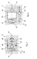
- FIG. 4 shows a second alternative embodiment of the hold-open valve 20 shown.
- the connections 41 and 42 are the same as in the Explained in connection with Figure 3.
- the difference to the embodiment according to Figure 3 is that the check valve 23 with the Spring element 26 is not integrated in the control piston 22, but in one Bypass 50 is arranged, the connection of the hydraulic line 42nd connects to piston chamber 1 with hydraulic line 41 to pump 6. There is no through bore within the control piston 22.
- the closing function is shown in the alternative embodiment in FIG the 2-2-way valve function through a separate closing body 9 realized in the form of a ball. This has the advantage that the Locking body 9 itself centered within a conical recess 53 and positional tolerances between the control piston 22 and the valve seat be balanced.
- the control piston 22 is also through the spring element 27 biased towards the closing body 9.
- FIG. 5 shows a third alternative embodiment of the hold-open valve 20, in contrast to the embodiments according to FIG Figure 3 and Figure 4, the inflow to the piston chamber 1 through the hydraulic line 42 and the bypass 50 and the return of the hydraulic fluid done separately by the hydraulic line 47.
- FIG. 6 shows a fourth alternative embodiment of the hold-open valve 20, in contrast to the previously described embodiments the 2-2-way valve is designed as a slide valve.
- the closing body of the 2-2-way valve is replaced by a cylindrical body formed, which closes the hydraulic line 46 depending on the switching position or releases.
- the hydraulic line 46 ends on the one hand again in the Space of the control piston 22 and at the same time in one of the hydraulic lines 42 upstream space 52, in which a piston 51 is located.
- the piston 51 is free-floating and much smaller in diameter than the control piston 22.
- FIG. 7 shows a fifth alternative embodiment of the hold-open valve 20 shown, in which an adjustable valve 28 between Hydraulic line 41 and 46 is arranged to when the drive is switched off to achieve a faster pressure equalization on the control piston 22 and thereby increase the switching speed of the 2-2-way valve 21 and at the same time by suitable adjustment of a valve 28 the resulting additional leakage during operation to an acceptable level Limit measure.
- FIG. 8 shows a sixth alternative embodiment of the hold-open valve 20, in contrast to the embodiment according to FIG Figure 7, the valve 28 is designed so that with increasing pressure in the Hydraulic line 41, the leakage flow additionally occurring at valve 28 is reduced or completely avoided when the operating pressure is reached can be.
- a throttle body 29 of the throttle valve is supported 28 on a spring 31, so that when the pressure in the hydraulic line increases 41 the gap of the valve seat to the throttle body 29 is reduced or is closed completely. In this way, a short switching time of the 2-2-way valve can be achieved without an additional leakage flow to have to put up with.
- the throttle body 29 stands with a Adjustment pin 30, which is equipped with a spring 32, in operative connection.
- the pump 6 When the door is opened, the pump 6 generates a volume flow of hydraulic fluid, which is conveyed into the piston chamber 1. To do this, the Pump 6 due to the inertia of the door and the force of the spring 3 exert a correspondingly increased pressure on the piston 2. This increased Pressure closes and prevents the 2-2-way valve through the control piston 22 thereby draining the volume of liquid conveyed into the tank room 8.
- the pump pressure is reduced.
- the Check valve 23 of the hydraulically controlled hold-open valve 20 the pressure in the piston chamber 1 is maintained and a backflow into the pump 6 prevented.
- the 2-2-way valve is replaced by a small one Control pressure from the pump 6 still kept closed.
- the unit consisting of pump 6 and motor 7 is complete off. This also happens in the event of a power failure. As a result, the pressure drops due to leakage in the pump 6 or on the control piston 22 or on the additional valve 28 below a limit value, where the 2-2-way valve opens so that the hydraulic fluid flows through the throttle valves 17 can flow into the tank space 8.
Landscapes
- Fluid-Pressure Circuits (AREA)
- Braking Arrangements (AREA)
- Power-Operated Mechanisms For Wings (AREA)
Applications Claiming Priority (2)
| Application Number | Priority Date | Filing Date | Title |
|---|---|---|---|
| DE10261224A DE10261224B3 (de) | 2002-12-20 | 2002-12-20 | Elektrohydraulischer Drehflügeltürantrieb |
| DE10261224 | 2002-12-20 |
Publications (2)
| Publication Number | Publication Date |
|---|---|
| EP1431495A2 true EP1431495A2 (fr) | 2004-06-23 |
| EP1431495A3 EP1431495A3 (fr) | 2009-05-27 |
Family
ID=31724880
Family Applications (1)
| Application Number | Title | Priority Date | Filing Date |
|---|---|---|---|
| EP03029121A Withdrawn EP1431495A3 (fr) | 2002-12-20 | 2003-12-18 | Entraînement électrohydraulique pour porte pivotante |
Country Status (3)
| Country | Link |
|---|---|
| EP (1) | EP1431495A3 (fr) |
| DE (1) | DE10261224B3 (fr) |
| NO (1) | NO20035665L (fr) |
Cited By (2)
| Publication number | Priority date | Publication date | Assignee | Title |
|---|---|---|---|---|
| DE102004061629A1 (de) * | 2004-12-17 | 2006-07-06 | Dorma Gmbh + Co. Kg | Drehtürantrieb |
| CN102296899A (zh) * | 2011-07-08 | 2011-12-28 | 肇庆市志盛门控五金有限公司 | 一种高密封性能的隐藏式闭门器 |
Families Citing this family (5)
| Publication number | Priority date | Publication date | Assignee | Title |
|---|---|---|---|---|
| DE102004061626B4 (de) * | 2004-12-17 | 2008-09-11 | Dorma Gmbh + Co. Kg | Türantrieb, insbesondere Drehtürantrieb |
| DE102004061624C5 (de) | 2004-12-17 | 2011-02-03 | Dorma Gmbh + Co. Kg | Türantrieb, insbesondere Drehtürantieb |
| DE102004061627B4 (de) | 2004-12-17 | 2007-02-01 | Dorma Gmbh + Co. Kg | Türschließer |
| DE102004061628B4 (de) * | 2004-12-17 | 2008-12-04 | Dorma Gmbh + Co. Kg | Türantrieb, insbesondere Drehtürantrieb |
| DE102005025475A1 (de) * | 2005-06-02 | 2006-12-07 | Hs Genion Gmbh | Tür mit Türbremse |
Family Cites Families (8)
| Publication number | Priority date | Publication date | Assignee | Title |
|---|---|---|---|---|
| US3396424A (en) * | 1967-06-19 | 1968-08-13 | Norris Industries | Door closer |
| DE3202966A1 (de) * | 1982-01-29 | 1983-08-11 | Geze Gmbh, 7250 Leonberg | Elektrohydraulische antriebseinheit fuer fluegel von tueren o.dgl. |
| DE3203390C2 (de) * | 1982-02-02 | 1986-12-11 | BKS Sicherheitstechnik GmbH, 5040 Brühl | Zahntrieb-Türschließer |
| FR2564518A1 (fr) * | 1984-05-15 | 1985-11-22 | Houdaille Lelaurain Sa | Vis de reglage perfectionnee pour ferme-porte de type hydraulique |
| DE3423242C1 (de) * | 1984-06-23 | 1985-11-07 | Dorma-Baubeschlag Gmbh & Co Kg, 5828 Ennepetal | Selbsttaetiger Tuerschliesser |
| DE4002747C3 (de) * | 1990-01-31 | 2002-09-05 | Geze Gmbh | Elektrohydraulische Antriebseinheit |
| DE4239172C1 (de) * | 1992-11-21 | 1993-12-16 | Daimler Benz Ag | Feststeller zum Halten eines Flügels in verschiedenen Öffnungsstellungen relativ zu seinem Rahmen |
| CH689055A5 (de) * | 1993-07-10 | 1998-08-31 | Geze Gmbh & Co | Drehtuerantrieb. |
-
2002
- 2002-12-20 DE DE10261224A patent/DE10261224B3/de not_active Expired - Fee Related
-
2003
- 2003-12-18 EP EP03029121A patent/EP1431495A3/fr not_active Withdrawn
- 2003-12-18 NO NO20035665A patent/NO20035665L/no not_active Application Discontinuation
Cited By (2)
| Publication number | Priority date | Publication date | Assignee | Title |
|---|---|---|---|---|
| DE102004061629A1 (de) * | 2004-12-17 | 2006-07-06 | Dorma Gmbh + Co. Kg | Drehtürantrieb |
| CN102296899A (zh) * | 2011-07-08 | 2011-12-28 | 肇庆市志盛门控五金有限公司 | 一种高密封性能的隐藏式闭门器 |
Also Published As
| Publication number | Publication date |
|---|---|
| NO20035665D0 (no) | 2003-12-18 |
| NO20035665L (no) | 2004-06-21 |
| DE10261224B3 (de) | 2004-05-13 |
| EP1431495A3 (fr) | 2009-05-27 |
Similar Documents
| Publication | Publication Date | Title |
|---|---|---|
| DE10261225B4 (de) | Elektrohydraulischer Servotürantrieb zum Antrieb einer Tür, eines Fensters oder dergleichen | |
| DE4333723C2 (de) | Hydraulischer Schwingungs-Dämpfer | |
| EP0715675B1 (fr) | Mecanisme d'entrainement d'une porte battante | |
| DE19909712B4 (de) | Steuerventileinrichtung für einen hydraulischen Verbraucher | |
| DE3908340A1 (de) | Tuerschliesser mit einer durch eine federanordnung im schliesssinn belasteten schliesserwelle | |
| EP0972902B1 (fr) | Ferme-porte à dimensions réduites | |
| DE2504892A1 (de) | Integrierte kraftlenkvorrichtung | |
| EP1828651B1 (fr) | Soupape de limitation de pression presentant une surface differentielle reduite | |
| DE10261224B3 (de) | Elektrohydraulischer Drehflügeltürantrieb | |
| DE2721705A1 (de) | Druckausgeglichenes ventil mit druckfuehleinrichtung | |
| DE102016208099B4 (de) | Antrieb für eine tür | |
| EP2960562A1 (fr) | Systeme de vannes | |
| EP3775576B1 (fr) | Dispositif de commande | |
| DE102014203879B4 (de) | Kolben-Zylinder-Einheit und Türscharnier | |
| DE69216050T2 (de) | Flüssigkeitskolbenpumpe mit Servohubsteuerung | |
| DE102005027573A1 (de) | Durchflussratensteuervorrichtung | |
| CH689055A5 (de) | Drehtuerantrieb. | |
| DE3003741A1 (de) | Tuerbetaetigungsanordnung | |
| DE10249509A1 (de) | Pneumatischer Stellantrieb | |
| DE102016218090B4 (de) | Ventilanordnung | |
| EP0328912B1 (fr) | Ferme-porte avec un dispositif d'arrêt hydraulique | |
| DE19914359C5 (de) | Geschirrspülmaschine mit oberem und unterem Sprüharm | |
| CH688203A5 (de) | Drehtürantrieb. | |
| DE19607878A1 (de) | Drehtürantrieb | |
| DE2127398C3 (de) | Hydrostatisches Reversiergetriebe |
Legal Events
| Date | Code | Title | Description |
|---|---|---|---|
| PUAI | Public reference made under article 153(3) epc to a published international application that has entered the european phase |
Free format text: ORIGINAL CODE: 0009012 |
|
| AK | Designated contracting states |
Kind code of ref document: A2 Designated state(s): AT BE BG CH CY CZ DE DK EE ES FI FR GB GR HU IE IT LI LU MC NL PT RO SE SI SK TR |
|
| AX | Request for extension of the european patent |
Extension state: AL LT LV MK |
|
| PUAL | Search report despatched |
Free format text: ORIGINAL CODE: 0009013 |
|
| AK | Designated contracting states |
Kind code of ref document: A3 Designated state(s): AT BE BG CH CY CZ DE DK EE ES FI FR GB GR HU IE IT LI LU MC NL PT RO SE SI SK TR |
|
| AX | Request for extension of the european patent |
Extension state: AL LT LV MK |
|
| STAA | Information on the status of an ep patent application or granted ep patent |
Free format text: STATUS: THE APPLICATION HAS BEEN WITHDRAWN |
|
| 18W | Application withdrawn |
Effective date: 20091016 |