EP1431564A2 - Méthode pour l'opération d'un moteur à combustion interne alimenté en gaz - Google Patents
Méthode pour l'opération d'un moteur à combustion interne alimenté en gaz Download PDFInfo
- Publication number
- EP1431564A2 EP1431564A2 EP03450272A EP03450272A EP1431564A2 EP 1431564 A2 EP1431564 A2 EP 1431564A2 EP 03450272 A EP03450272 A EP 03450272A EP 03450272 A EP03450272 A EP 03450272A EP 1431564 A2 EP1431564 A2 EP 1431564A2
- Authority
- EP
- European Patent Office
- Prior art keywords
- gas
- combustion chamber
- blown
- chamber
- mixture
- Prior art date
- Legal status (The legal status is an assumption and is not a legal conclusion. Google has not performed a legal analysis and makes no representation as to the accuracy of the status listed.)
- Granted
Links
Images
Classifications
-
- F—MECHANICAL ENGINEERING; LIGHTING; HEATING; WEAPONS; BLASTING
- F02—COMBUSTION ENGINES; HOT-GAS OR COMBUSTION-PRODUCT ENGINE PLANTS
- F02B—INTERNAL-COMBUSTION PISTON ENGINES; COMBUSTION ENGINES IN GENERAL
- F02B19/00—Engines characterised by precombustion chambers
- F02B19/02—Engines characterised by precombustion chambers the chamber being periodically isolated from its cylinder
-
- F—MECHANICAL ENGINEERING; LIGHTING; HEATING; WEAPONS; BLASTING
- F02—COMBUSTION ENGINES; HOT-GAS OR COMBUSTION-PRODUCT ENGINE PLANTS
- F02B—INTERNAL-COMBUSTION PISTON ENGINES; COMBUSTION ENGINES IN GENERAL
- F02B19/00—Engines characterised by precombustion chambers
- F02B19/10—Engines characterised by precombustion chambers with fuel introduced partly into pre-combustion chamber, and partly into cylinder
- F02B19/1019—Engines characterised by precombustion chambers with fuel introduced partly into pre-combustion chamber, and partly into cylinder with only one pre-combustion chamber
- F02B19/108—Engines characterised by precombustion chambers with fuel introduced partly into pre-combustion chamber, and partly into cylinder with only one pre-combustion chamber with fuel injection at least into pre-combustion chamber, i.e. injector mounted directly in the pre-combustion chamber
-
- F—MECHANICAL ENGINEERING; LIGHTING; HEATING; WEAPONS; BLASTING
- F02—COMBUSTION ENGINES; HOT-GAS OR COMBUSTION-PRODUCT ENGINE PLANTS
- F02B—INTERNAL-COMBUSTION PISTON ENGINES; COMBUSTION ENGINES IN GENERAL
- F02B21/00—Engines characterised by air-storage chambers
-
- F—MECHANICAL ENGINEERING; LIGHTING; HEATING; WEAPONS; BLASTING
- F02—COMBUSTION ENGINES; HOT-GAS OR COMBUSTION-PRODUCT ENGINE PLANTS
- F02M—SUPPLYING COMBUSTION ENGINES IN GENERAL WITH COMBUSTIBLE MIXTURES OR CONSTITUENTS THEREOF
- F02M21/00—Apparatus for supplying engines with non-liquid fuels, e.g. gaseous fuels stored in liquid form
- F02M21/02—Apparatus for supplying engines with non-liquid fuels, e.g. gaseous fuels stored in liquid form for gaseous fuels
- F02M21/0218—Details on the gaseous fuel supply system, e.g. tanks, valves, pipes, pumps, rails, injectors or mixers
- F02M21/0248—Injectors
- F02M21/0275—Injectors for in-cylinder direct injection, e.g. injector combined with spark plug
-
- Y—GENERAL TAGGING OF NEW TECHNOLOGICAL DEVELOPMENTS; GENERAL TAGGING OF CROSS-SECTIONAL TECHNOLOGIES SPANNING OVER SEVERAL SECTIONS OF THE IPC; TECHNICAL SUBJECTS COVERED BY FORMER USPC CROSS-REFERENCE ART COLLECTIONS [XRACs] AND DIGESTS
- Y02—TECHNOLOGIES OR APPLICATIONS FOR MITIGATION OR ADAPTATION AGAINST CLIMATE CHANGE
- Y02T—CLIMATE CHANGE MITIGATION TECHNOLOGIES RELATED TO TRANSPORTATION
- Y02T10/00—Road transport of goods or passengers
- Y02T10/10—Internal combustion engine [ICE] based vehicles
- Y02T10/12—Improving ICE efficiencies
-
- Y—GENERAL TAGGING OF NEW TECHNOLOGICAL DEVELOPMENTS; GENERAL TAGGING OF CROSS-SECTIONAL TECHNOLOGIES SPANNING OVER SEVERAL SECTIONS OF THE IPC; TECHNICAL SUBJECTS COVERED BY FORMER USPC CROSS-REFERENCE ART COLLECTIONS [XRACs] AND DIGESTS
- Y02—TECHNOLOGIES OR APPLICATIONS FOR MITIGATION OR ADAPTATION AGAINST CLIMATE CHANGE
- Y02T—CLIMATE CHANGE MITIGATION TECHNOLOGIES RELATED TO TRANSPORTATION
- Y02T10/00—Road transport of goods or passengers
- Y02T10/10—Internal combustion engine [ICE] based vehicles
- Y02T10/30—Use of alternative fuels, e.g. biofuels
Definitions
- the invention relates to a method for operating a gas-operated Internal combustion engine, wherein the gas is injected into a Blown combustion chamber and a stratified charge is generated. Furthermore concerns the invention is a gas-powered internal combustion engine with at least one High-pressure gas accumulator, with at least one blowing device per cylinder and a distribution line between the high-pressure gas reservoir and the blowing device, and one arranged between the high pressure accumulator and the distribution line Pressure regulator, the blowing device with one over the combustion chamber has a switchable valve, preferably a lift valve, connectable chamber, into which a gas supply line emanating from the distribution line opens.
- US 4,574,754 A1 discloses an internal combustion engine for gaseous fuel, in which the gas is blown into the combustion chamber so that a stratified charge arises.
- homogeneous mixture preparation can be achieved through the oxygen-rich environment achieve a more perfect combustion of the fuel gas in the combustion chamber, what has a beneficial effect on emissions and efficiency.
- the disadvantage is that with this turbulence-controlled charge stratification, the ignition range is relatively narrow, so that only a relatively low ignition stability is achieved can be.
- the US 6,161,527 A shows such an air-assisted Fuel injection system in which fuel is premixed with air and this Mixture is injected into the combustion chamber via a controlled valve.
- the AT 407.559 B describes a device for introducing fuel into the Combustion chamber of an internal combustion engine that uses gas during a working cycle removed from the combustion chamber and a chamber via a controlled lift valve is fed. The gas is temporarily stored in the chamber and in the gas the fuel delivered by a pump is injected. In the following Working cycle is the mixture of fuel and gas in the combustion chamber blown. This enables a stratified charge to be generated in the combustion chamber and the efficiency and pollutant emissions are simple and effective improve.
- the object of the invention is to avoid the disadvantages mentioned and at gas powered internal combustion engine nitrogen oxide and hydrocarbon emissions to reduce significantly.
- a fuel gas preferably Natural gas, hydrogen or a mixture of flammable gases
- a switchable valve Chamber is blown and mixed with a second gas, and that this The gas mixture is blown directly into the combustion chamber by opening the switchable valve becomes.
- the gas mixture is preferably in a crank angle range between about 130 ° to 45 ° crank angle before top dead center in blown into the combustion chamber.
- the fuel gas can be extracted with air or with the combustion chamber in the chamber Gas to be mixed.
- Mixing with gas from the combustion chamber can be carried out in a simple manner in that a relatively small amount (approximately 6 to 12 cm 3 ) of compressed hot gas is removed from the combustion chamber and stored in the chamber during a work cycle, so that the fuel gas flows into the hot one Gas is blown in and that the stored gas mixture is blown into the combustion chamber in the subsequent cycle.
- a blowing device is suitable for carrying out the method reloading gas taken from the combustion chamber into a chamber the blowing device is possible.
- a control valve is arranged in the gas supply line.
- the fuel gas is blown into the combustion chamber premixed with air or gas taken from the combustion chamber.
- a stratified charge is created by the injection, which has a very wide combustible mixture area. Due to the high ignition stability, the hydrocarbon emissions can be significantly reduced. Since driving is only carried out in the very lean mixture area, only very low NO x emissions arise.
- the switchable valve of the blowing device can be mechanical, electrical, hydraulic or operated pneumatically.
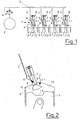
- the gas-powered internal combustion engine 1 has a high-pressure accumulator 2 for the fuel gas, which is, for example, natural gas, hydrogen, a mixture of flammable gases or the like.
- a distribution line 3 goes out, between the distribution line 3 and the high-pressure accumulator 2, a pressure regulator 4 is arranged, which is under a pressure fuel gas stored in the high-pressure accumulator 2 from about 200 bar to a supply pressure throttled by, for example, about 6 bar.
- From the supply line 3 goes out per cylinder 4 at least one gas supply line 5, which over a control valve 6 opens into a chamber 7 of a blowing device 8.
- the Chamber 7 is connected to a switchable valve 9, preferably a lift valve Combustion chamber of a cylinder 4 connected.
- the valve 9 can be hydraulic, pneumatic, be mechanically or electrically operable.
- Reference number 11 denotes an ignition device opening into the combustion chamber 10 designated.
- the chamber 7 of the blowing device 8 serves as a premixing space and as a gas storage.
- the fuel gas is blown directly into the chamber 7 via the control valve 6. If the fuel gas is mixed with the gas previously removed from the combustion chamber, the blowing device 8 itself removes a relatively small amount of about 6 to 12 cm 3 (size of the chamber 7) of compressed hot gas from the combustion chamber 10 during a working cycle by the Valve 9 is kept open for a correspondingly long time after the end of the blowing process into combustion chamber 10. This gas removed from the combustion chamber 10 is temporarily stored in the chamber 7 and the fuel gas is then blown into the gas stored in the chamber 7 via the control valve 6.
- the mixture of fuel gas and gas removed from the combustion chamber 10 is blown into the combustion chamber 10, as a result of which a stratified charge 16 is generated in the combustion chamber 10.
- the gas mixture blown into the combustion chamber 10 has a local air ratio between 1 and 1.7.
Landscapes
- Engineering & Computer Science (AREA)
- Chemical & Material Sciences (AREA)
- Combustion & Propulsion (AREA)
- Mechanical Engineering (AREA)
- General Engineering & Computer Science (AREA)
- Chemical Kinetics & Catalysis (AREA)
- General Chemical & Material Sciences (AREA)
- Oil, Petroleum & Natural Gas (AREA)
- Combustion Methods Of Internal-Combustion Engines (AREA)
- Output Control And Ontrol Of Special Type Engine (AREA)
Applications Claiming Priority (2)
| Application Number | Priority Date | Filing Date | Title |
|---|---|---|---|
| AT0085602U AT7202U1 (de) | 2002-12-19 | 2002-12-19 | Verfahren zum betreiben einer mit gas betriebenen brennkraftmaschine |
| AT8562002U | 2002-12-19 |
Publications (3)
| Publication Number | Publication Date |
|---|---|
| EP1431564A2 true EP1431564A2 (fr) | 2004-06-23 |
| EP1431564A3 EP1431564A3 (fr) | 2005-05-04 |
| EP1431564B1 EP1431564B1 (fr) | 2007-06-13 |
Family
ID=32330365
Family Applications (1)
| Application Number | Title | Priority Date | Filing Date |
|---|---|---|---|
| EP03450272A Expired - Lifetime EP1431564B1 (fr) | 2002-12-19 | 2003-12-04 | Méthode pour l'opération d'un moteur à combustion interne alimenté en gaz |
Country Status (6)
| Country | Link |
|---|---|
| US (1) | US20040149254A1 (fr) |
| EP (1) | EP1431564B1 (fr) |
| JP (1) | JP2004197751A (fr) |
| CN (1) | CN1508409A (fr) |
| AT (1) | AT7202U1 (fr) |
| DE (1) | DE50307459D1 (fr) |
Cited By (6)
| Publication number | Priority date | Publication date | Assignee | Title |
|---|---|---|---|---|
| EP1561940A3 (fr) * | 2004-02-09 | 2006-06-28 | Wieslaw Wiatrak | Un système d'injection de combustible assisté par la recirculation de gaz d'échappement |
| WO2009079725A1 (fr) | 2007-12-24 | 2009-07-02 | Erwin Erik Paul Georges Vandenberghe | Moteur à combustion interne et procédé pour adapter un moteur à combustion interne |
| ITPI20090143A1 (it) * | 2009-11-18 | 2011-05-19 | Univ Pisa | Sistema di iniezione diretta di idrogeno per motori ad ac |
| EP2932079A4 (fr) * | 2012-12-17 | 2016-09-21 | Westport Power Inc | Injection directe de carburant gazeux enrichi en air pour un moteur à combustion interne |
| DE102017120512A1 (de) | 2017-09-06 | 2019-03-07 | Keyou GmbH | Verfahren zum Betreiben eines Gasmotors, insbesondere eines Wasserstoffmotors, insbesondere für ein Kraftfahrzeug |
| AT520481A1 (de) * | 2017-10-02 | 2019-04-15 | Avl List Gmbh | Injektionssystem für ein Brennstoffzellensystem zum Einspritzen von Brennstoff in einen Brennraum |
Families Citing this family (14)
| Publication number | Priority date | Publication date | Assignee | Title |
|---|---|---|---|---|
| RU2291316C1 (ru) * | 2005-08-03 | 2007-01-10 | ООО "Завод "Газпроммаш" | Устройство подачи природного газа с внешним смесеобразованием в двигатель |
| RU2443898C2 (ru) * | 2009-10-28 | 2012-02-27 | ГОУ ВПО "Санкт-Петербургский государственный архитектурно-строительный университет" | Система подачи газовоздушной смеси в двигатель |
| US8919259B2 (en) | 2012-07-31 | 2014-12-30 | Electro-Motive Diesel, Inc. | Fuel system for consist having daughter locomotive |
| US8960100B2 (en) | 2012-07-31 | 2015-02-24 | Electro-Motive Diesel, Inc. | Energy recovery system for a mobile machine |
| US8925465B2 (en) | 2012-07-31 | 2015-01-06 | Electro-Motive Diesel, Inc. | Consist having self-propelled tender car |
| US9193362B2 (en) | 2012-07-31 | 2015-11-24 | Electro-Motive Diesel, Inc. | Consist power system having auxiliary load management |
| US8899158B2 (en) | 2012-07-31 | 2014-12-02 | Electro-Motive Diesel, Inc. | Consist having self-powered tender car |
| US8955444B2 (en) | 2012-07-31 | 2015-02-17 | Electro-Motive Diesel, Inc. | Energy recovery system for a mobile machine |
| US9073556B2 (en) * | 2012-07-31 | 2015-07-07 | Electro-Motive Diesel, Inc. | Fuel distribution system for multi-locomotive consist |
| JP5846448B2 (ja) * | 2012-10-23 | 2016-01-20 | 株式会社デンソー | 気体燃料用圧力制御装置 |
| WO2015110257A2 (fr) * | 2014-01-21 | 2015-07-30 | Peter Kreuter | Moteur à combustion interne à piston alternatif ainsi que procédé pour faire fonctionner un moteur à combustion interne à piston alternatif |
| US10584639B2 (en) | 2014-08-18 | 2020-03-10 | Woodward, Inc. | Torch igniter |
| US11421601B2 (en) | 2019-03-28 | 2022-08-23 | Woodward, Inc. | Second stage combustion for igniter |
| CN116209823A (zh) | 2020-06-23 | 2023-06-02 | 伍德沃德有限公司 | 针对功率生成发动机的点火系统 |
Family Cites Families (14)
| Publication number | Priority date | Publication date | Assignee | Title |
|---|---|---|---|---|
| US3703886A (en) * | 1970-11-09 | 1972-11-28 | Julius E Witzky | Pumpless stratified charge gas engine |
| US4574754A (en) * | 1982-08-16 | 1986-03-11 | Rhoades Jr Warren A | Stratified charge combustion system and method for gaseous fuel internal combustion engines |
| DE3872217D1 (de) * | 1987-08-12 | 1992-07-23 | Avl Verbrennungskraft Messtech | Einrichtung zur einbringung des kraftstoffes in den brennraum einer brennkraftmaschine. |
| US4865001A (en) * | 1988-11-28 | 1989-09-12 | Energy Conversions, Inc. | Gaseous fuel injector valve |
| US4944277A (en) * | 1989-03-03 | 1990-07-31 | Outboard Marine Corporation | Cylinder entrapment system with an air spring |
| US5329908A (en) * | 1993-06-08 | 1994-07-19 | Cummins Engine Company, Inc. | Compressed natural gas injection system for gaseous fueled engines |
| AT408138B (de) * | 1995-02-23 | 2001-09-25 | Avl Verbrennungskraft Messtech | Einrichtung zum einbringen von kraftstoff in den brennraum einer brennkraftmaschine |
| AT408137B (de) * | 1995-02-27 | 2001-09-25 | Avl Verbrennungskraft Messtech | Einrichtung zum einbringen von kraftstoff in den brennraum einer brennkraftmaschine |
| AUPN489595A0 (en) * | 1995-08-18 | 1995-09-14 | Orbital Engine Company (Australia) Proprietary Limited | Gaseous fuel direct injection system for internal combustion engines |
| GB2304811A (en) * | 1995-08-26 | 1997-03-26 | Ford Motor Co | Engine intake fuel atomisation |
| JPH09256850A (ja) * | 1996-03-25 | 1997-09-30 | Isuzu Ceramics Kenkyusho:Kk | 副室式ガスエンジン |
| US6298825B1 (en) * | 1998-11-27 | 2001-10-09 | Fev Motorentechnik Gmbh | Method for igniting a multi-cylinder reciprocating gas engine by injecting an ignition gas |
| US6161527A (en) * | 1999-02-11 | 2000-12-19 | Brunswick Corporation | Air assisted direct fuel injection system |
| DE19923346C2 (de) * | 1999-02-19 | 2002-11-14 | Stefanie Dosch | Motor |
-
2002
- 2002-12-19 AT AT0085602U patent/AT7202U1/de not_active IP Right Cessation
-
2003
- 2003-12-04 EP EP03450272A patent/EP1431564B1/fr not_active Expired - Lifetime
- 2003-12-04 DE DE50307459T patent/DE50307459D1/de not_active Expired - Lifetime
- 2003-12-18 US US10/738,211 patent/US20040149254A1/en not_active Abandoned
- 2003-12-19 CN CNA2003101239365A patent/CN1508409A/zh active Pending
- 2003-12-19 JP JP2003421750A patent/JP2004197751A/ja active Pending
Cited By (12)
| Publication number | Priority date | Publication date | Assignee | Title |
|---|---|---|---|---|
| EP1561940A3 (fr) * | 2004-02-09 | 2006-06-28 | Wieslaw Wiatrak | Un système d'injection de combustible assisté par la recirculation de gaz d'échappement |
| WO2009079725A1 (fr) | 2007-12-24 | 2009-07-02 | Erwin Erik Paul Georges Vandenberghe | Moteur à combustion interne et procédé pour adapter un moteur à combustion interne |
| BE1017913A5 (nl) * | 2007-12-24 | 2009-11-03 | Vandenberghe Erwin Erik Paul Georges | Interne verbrandingsmotor. |
| ITPI20090143A1 (it) * | 2009-11-18 | 2011-05-19 | Univ Pisa | Sistema di iniezione diretta di idrogeno per motori ad ac |
| EP2932079A4 (fr) * | 2012-12-17 | 2016-09-21 | Westport Power Inc | Injection directe de carburant gazeux enrichi en air pour un moteur à combustion interne |
| US10233871B2 (en) | 2012-12-17 | 2019-03-19 | Westport Power Inc. | Air-enriched gaseous fuel direct injection for an internal combustion engine |
| DE102017120512A1 (de) | 2017-09-06 | 2019-03-07 | Keyou GmbH | Verfahren zum Betreiben eines Gasmotors, insbesondere eines Wasserstoffmotors, insbesondere für ein Kraftfahrzeug |
| WO2019048454A1 (fr) | 2017-09-06 | 2019-03-14 | Keyou GmbH | Procédé pour faire fonctionner un moteur à gaz |
| US11268460B2 (en) | 2017-09-06 | 2022-03-08 | Keyou GmbH | Method for operating a gas engine |
| DE102017120512B4 (de) | 2017-09-06 | 2022-09-29 | Keyou GmbH | Verfahren zum Betreiben eines Wasserstoffmotors für ein Kraftfahrzeug |
| AT520481A1 (de) * | 2017-10-02 | 2019-04-15 | Avl List Gmbh | Injektionssystem für ein Brennstoffzellensystem zum Einspritzen von Brennstoff in einen Brennraum |
| AT520481B1 (de) * | 2017-10-02 | 2020-03-15 | Avl List Gmbh | Injektionssystem für ein Brennstoffzellensystem zum Einspritzen von Brennstoff in einen Brennraum |
Also Published As
| Publication number | Publication date |
|---|---|
| US20040149254A1 (en) | 2004-08-05 |
| CN1508409A (zh) | 2004-06-30 |
| JP2004197751A (ja) | 2004-07-15 |
| EP1431564B1 (fr) | 2007-06-13 |
| EP1431564A3 (fr) | 2005-05-04 |
| AT7202U1 (de) | 2004-11-25 |
| DE50307459D1 (de) | 2007-07-26 |
Similar Documents
| Publication | Publication Date | Title |
|---|---|---|
| EP1431564A2 (fr) | Méthode pour l'opération d'un moteur à combustion interne alimenté en gaz | |
| DE112007000944B4 (de) | Hochleistungsmaschinen mit geringer Emission, Mehrzylindermaschinen und Betriebsverfahren | |
| DE3400306C1 (de) | Verfahren zum Betreiben einer fremdgezuendeten Brennkraftmaschine von Kraftfahrzeugen | |
| DE60310979T2 (de) | Methode und vorkammerzündeinrichtung für eine brennkraftmaschine | |
| EP3988780B1 (fr) | Injecteur de carburant d'une machine à combustion interne à bi-carburant, machine à combustion interne à bi-carburant et son procédé de fonctionnement | |
| EP1039112A2 (fr) | Système d'alimentation de combustible pour un moteur à combustion interne à allumage commandé | |
| DE2556619A1 (de) | Arbeitsverfahren fuer eine brennkraftmaschine und brennkraftmaschine zur durchfuehrung des verfahrens | |
| EP1323908A2 (fr) | Procédé d'opération d'un moteur à combustion interne | |
| DE102010033394A1 (de) | Verfahren zum Betreiben eines Verbrennungsmotors mit Funkenzündung | |
| DE102019209232A1 (de) | HPDF-Betriebsverfahren für eine Brennkraftmaschine, Brennkraftmaschine und Arbeitsvorrichtung | |
| EP3872330A1 (fr) | Procédé de fonctionnement d'un grand moteur diesel, ainsi que grand moteur diesel | |
| DE19945544A1 (de) | Brennstoffzuführsystem für eine fremdgezündete Brennkraftmaschine und Verfahren zum Betrieb einer solchen Brennkraftmaschine | |
| EP3404235A1 (fr) | Gros moteur diesel et procédé de fonctionnement d'un gros moteur diesel | |
| DE102004043143A1 (de) | Verfahren und Vorrichtung zur Entflammung von Kraftstoff-Luft-Gemischen bei einem Gas-Verbrennungsmotor mit Vorkammerzündung | |
| EP1585897A2 (fr) | Systeme d'injection pour moteur a combustion interne | |
| DE10361665B4 (de) | Benzin-Direkteinspritzungs-System | |
| DE10307166A1 (de) | Verfahren zum Betrieb einer fremdgezündeten Brennkraftmaschine | |
| DE10043384A1 (de) | Brennkraftmaschine mit innerer und äußerer Gemischbildung | |
| DE10214987B4 (de) | Verbrennungsmotor und Verfahren zum Erzeugen von Bewegungsenergie aus kohlenwasserstoffhaltigen Kraftstoffen | |
| DE102017201805A1 (de) | Verfahren zum Einspritzen eines Zusatzmediums in den Zylinder einer fremdgezündeten Brennkraftmaschine und Brennkraftmaschine zur Durchführung eines derartigen Verfahrens | |
| EP3926154A1 (fr) | Gros moteur purgé longitudinalement | |
| DE102019006486A1 (de) | Verfahren zum Betreiben einer Brennkraftmaschine, aufweisend eine Hauptbrennkammer und eine Vorkammer, mit Gaskraftstoff. | |
| DE102022103532B4 (de) | Verfahren zum Betreiben einer Brennkraftmaschine sowie entsprechende Brennkraftmaschine | |
| DE704893C (de) | Arbeitsverfahren fuer fremdgezuendete Zweitaktbrennkraftmaschinen, bei denen Brennstoff eingespritzt wird | |
| DE612133C (de) | Einspritzvorrichtung fuer Rohoelbrennkraftmaschinen |
Legal Events
| Date | Code | Title | Description |
|---|---|---|---|
| PUAI | Public reference made under article 153(3) epc to a published international application that has entered the european phase |
Free format text: ORIGINAL CODE: 0009012 |
|
| AK | Designated contracting states |
Kind code of ref document: A2 Designated state(s): AT BE BG CH CY CZ DE DK EE ES FI FR GB GR HU IE IT LI LU MC NL PT RO SE SI SK TR |
|
| AX | Request for extension of the european patent |
Extension state: AL LT LV MK |
|
| PUAL | Search report despatched |
Free format text: ORIGINAL CODE: 0009013 |
|
| AK | Designated contracting states |
Kind code of ref document: A3 Designated state(s): AT BE BG CH CY CZ DE DK EE ES FI FR GB GR HU IE IT LI LU MC NL PT RO SE SI SK TR |
|
| AX | Request for extension of the european patent |
Extension state: AL LT LV MK |
|
| RIC1 | Information provided on ipc code assigned before grant |
Ipc: 7F 02B 17/00 B Ipc: 7F 02B 43/04 B Ipc: 7F 02M 21/02 A |
|
| 17P | Request for examination filed |
Effective date: 20051022 |
|
| AKX | Designation fees paid |
Designated state(s): DE FR IT |
|
| GRAP | Despatch of communication of intention to grant a patent |
Free format text: ORIGINAL CODE: EPIDOSNIGR1 |
|
| GRAS | Grant fee paid |
Free format text: ORIGINAL CODE: EPIDOSNIGR3 |
|
| GRAA | (expected) grant |
Free format text: ORIGINAL CODE: 0009210 |
|
| AK | Designated contracting states |
Kind code of ref document: B1 Designated state(s): DE FR IT |
|
| REF | Corresponds to: |
Ref document number: 50307459 Country of ref document: DE Date of ref document: 20070726 Kind code of ref document: P |
|
| ET | Fr: translation filed | ||
| PLBE | No opposition filed within time limit |
Free format text: ORIGINAL CODE: 0009261 |
|
| STAA | Information on the status of an ep patent application or granted ep patent |
Free format text: STATUS: NO OPPOSITION FILED WITHIN TIME LIMIT |
|
| 26N | No opposition filed |
Effective date: 20080314 |
|
| PGFP | Annual fee paid to national office [announced via postgrant information from national office to epo] |
Ref country code: IT Payment date: 20101229 Year of fee payment: 8 Ref country code: DE Payment date: 20101201 Year of fee payment: 8 |
|
| PGFP | Annual fee paid to national office [announced via postgrant information from national office to epo] |
Ref country code: FR Payment date: 20111223 Year of fee payment: 9 |
|
| REG | Reference to a national code |
Ref country code: FR Ref legal event code: ST Effective date: 20130830 |
|
| REG | Reference to a national code |
Ref country code: DE Ref legal event code: R119 Ref document number: 50307459 Country of ref document: DE Effective date: 20130702 |
|
| PG25 | Lapsed in a contracting state [announced via postgrant information from national office to epo] |
Ref country code: DE Free format text: LAPSE BECAUSE OF NON-PAYMENT OF DUE FEES Effective date: 20130702 |
|
| PG25 | Lapsed in a contracting state [announced via postgrant information from national office to epo] |
Ref country code: FR Free format text: LAPSE BECAUSE OF NON-PAYMENT OF DUE FEES Effective date: 20130102 |
|
| PG25 | Lapsed in a contracting state [announced via postgrant information from national office to epo] |
Ref country code: IT Free format text: LAPSE BECAUSE OF NON-PAYMENT OF DUE FEES Effective date: 20121204 |