EP1431567A2 - Brennstoffeinspritzventil für Verbrennungskraftmaschinen - Google Patents
Brennstoffeinspritzventil für Verbrennungskraftmaschinen Download PDFInfo
- Publication number
- EP1431567A2 EP1431567A2 EP04006794A EP04006794A EP1431567A2 EP 1431567 A2 EP1431567 A2 EP 1431567A2 EP 04006794 A EP04006794 A EP 04006794A EP 04006794 A EP04006794 A EP 04006794A EP 1431567 A2 EP1431567 A2 EP 1431567A2
- Authority
- EP
- European Patent Office
- Prior art keywords
- control
- injection valve
- housing
- chamber
- valve member
- Prior art date
- Legal status (The legal status is an assumption and is not a legal conclusion. Google has not performed a legal analysis and makes no representation as to the accuracy of the status listed.)
- Granted
Links
Images


Classifications
-
- F—MECHANICAL ENGINEERING; LIGHTING; HEATING; WEAPONS; BLASTING
- F02—COMBUSTION ENGINES; HOT-GAS OR COMBUSTION-PRODUCT ENGINE PLANTS
- F02M—SUPPLYING COMBUSTION ENGINES IN GENERAL WITH COMBUSTIBLE MIXTURES OR CONSTITUENTS THEREOF
- F02M61/00—Fuel-injectors not provided for in groups F02M39/00 - F02M57/00 or F02M67/00
- F02M61/16—Details not provided for in, or of interest apart from, the apparatus of groups F02M61/02 - F02M61/14
- F02M61/20—Closing valves mechanically, e.g. arrangements of springs or weights or permanent magnets; Damping of valve lift
-
- F—MECHANICAL ENGINEERING; LIGHTING; HEATING; WEAPONS; BLASTING
- F02—COMBUSTION ENGINES; HOT-GAS OR COMBUSTION-PRODUCT ENGINE PLANTS
- F02M—SUPPLYING COMBUSTION ENGINES IN GENERAL WITH COMBUSTIBLE MIXTURES OR CONSTITUENTS THEREOF
- F02M47/00—Fuel-injection apparatus operated cyclically with fuel-injection valves actuated by fluid pressure
- F02M47/02—Fuel-injection apparatus operated cyclically with fuel-injection valves actuated by fluid pressure of accumulator-injector type, i.e. having fuel pressure of accumulator tending to open, and fuel pressure in other chamber tending to close, injection valves and having means for periodically releasing that closing pressure
- F02M47/027—Electrically actuated valves draining the chamber to release the closing pressure
-
- F—MECHANICAL ENGINEERING; LIGHTING; HEATING; WEAPONS; BLASTING
- F02—COMBUSTION ENGINES; HOT-GAS OR COMBUSTION-PRODUCT ENGINE PLANTS
- F02M—SUPPLYING COMBUSTION ENGINES IN GENERAL WITH COMBUSTIBLE MIXTURES OR CONSTITUENTS THEREOF
- F02M2547/00—Special features for fuel-injection valves actuated by fluid pressure
- F02M2547/003—Valve inserts containing control chamber and valve piston
Definitions
- the present invention relates to a fuel injector for intermittent fuel injection in the combustion chamber of an internal combustion engine with the Features in the preamble of claim 1.
- a fuel injector that features in The preamble of claim 1 is in EP-A-0 426 205.
- this fuel injector is a control room on the circumference of a housing of the Fuel injector and, in the axial direction seen, on the one hand from a double-acting control piston an injection valve member and on the other hand by one Intermediate valve body that between itself and the housing leaves an annular gap free, and one the annular gap limiting control body, which is arranged fixed to the housing, limited.
- a compression spring is arranged between the control piston and the intermediate valve body. In axial Direction runs through the intermediate valve body a stepped bore that throttles.
- This hole runs through the control body through another hole, which by means of a electromagnetically operated pilot valve with a Low pressure space can be connected and separated from it.
- this axial bore in the Control body opens another hole with a circumferential annular groove in the control body in connection stands, which in turn with the high pressure inlet of the Fuel injector is connected.
- the ring groove runs several holes to the intermediate valve body facing end face of the control body.
- the older EP-A-1 118 765 discloses one Fuel injection valve for internal combustion engines, whose needle-shaped injection valve member one has stepped control piston, which in a as Closing spring for the compression spring acting on the injection valve supporting sleeve engages. On the side facing away from the spring The sleeve is supported on a control body which fixed in a housing of the fuel injector is arranged. The sleeve has one through a shoulder formed extension on. In this extension is a arranged sleeve-shaped valve body, being between this and the sleeve has a gap.
- the valve body works with its axial faces on the one hand with the shoulder and on the other hand with the Control body together, the length of the valve body is slightly smaller than the distance between the Shoulder and the control body so that the valve body back and forth in the axial direction by a small stroke can move.
- the smaller part of the diameter The spool is in a tight sliding fit in the Valve body guided.
- a larger part of the control piston is an annulus trained with one inside the housing arranged and with a high pressure inlet Fuel-fed high-pressure space through a gap connected between the corresponding part of the Sleeve and the larger part of the diameter Control piston is formed.
- a control room is on the one hand from the control piston, on the other hand from the control body and limited on the circumference by the sleeve-shaped valve body.
- a constriction acting as a throttle Control passage passes through the control body from the the front side delimiting the control room opposite end face that has a low pressure space limited.
- the tax passage is by means of a electromagnetically operated pilot valve with the Low pressure room connectable or separable at this.
- Fuel injector is extremely compact at the same time. It takes up little space.
- the characteristics of the Fuel injector can by the Injector according to the invention provided Possibilities in a simple way the requirements be adapted to suit.
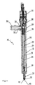
- Fig. 1 shows an axial section through a Fuel injector 10.
- the housing 12 has a high-pressure inlet 18 serving bore running in the radial direction, through which a high pressure (200-2000 bar or more) fuel in a case limited High pressure space 20 is introduced, which is in the axial Direction to the end of the valve seat element Housing 12 extends.
- Annular space 25 is the valve seat element 14 with the High pressure inlet 18 fluidly connected.
- a hydraulic control device 26 for the Injection valve member 22 which is further below in Describe connection with FIGS. 2 and 4 in more detail will be.
- the housing 12 extends through a connecting sleeve 28 a threaded flange 30 projecting in the radial direction, in which a high pressure connection piece 32 is threaded is.
- a high pressure connection piece 32 is threaded is.
- the wall of the high pressure connector 32 in the Housing 12 facing end region tapers trained so that the width of the front annular sealing surface 34 is smaller than the thickness of the Wall of the high pressure connection piece 32 on the rest Make, which is between the sealing surface 34 and the cooperating counter sealing surface 36 on the housing 12 a high when tightening the high-pressure connection piece 32 Surface pressure and thus a high pressure tight connection results.
- the High-pressure connection piece 32 is the connection sleeve 28 attached to the housing 12.
- the housing 12 on the outside, for axial positioning of the connecting sleeve 28, a Can have shoulder.
- the high-pressure connection piece 32 has the conical one Rejuvenation on the outside, with the same effect like the taper shown on the inner wall of High pressure connection piece 32.
- the High-pressure connection piece 32 can also be used with others Mean, as a thread pressed against the sealing surface 34 become.
- valve seat element 14 is in known manner by means of a union nut 38 on Housing 12 attached. From the cone-shaped free outer end face 40 of the valve seat element 14 run in a known manner Injector nozzle holes 42, which in the high pressure space 20th lead. A conical inner one The end face of the valve seat element 14 is a valve seat 44 trained and to cooperate with the opposite shaped end portion of the injector member 22 certainly. This end area separates in the closed position located injection valve member 22 the Injection nozzle holes 42 from the high pressure space or connects this to that when it is in the injection position is lifted off the valve seat 44.
- the injection valve member 22 is by means of a Compression spring trained locking spring 46 in Prestressed closing direction.
- the shaft 48 of the Injection valve member 22 has a shoulder 50 which is supported by two half-support flanges 52 - see Fig. 3b - the assembled one from a first ring 54 includes and are held together.
- One end of the Closing spring 46 is supported on this first ring 54.
- the other end is supported on a second ring 54 ', the one piece on a slot Support flange 56 sits. This in turn is due to the Face of a substantially hollow cylindrical Sleeve 58 to that associated with the control device 26 will be described in more detail.
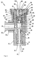
- the control device 26 is described with reference to FIG. 4. It can be seen from this that the injection valve member 22 in its end region facing away from the valve seat element 14 has a double-acting control piston 60, which in sleeve 58 in a tight sliding fit - i.e. with a Game of about 1 to 10 microns - is performed.
- the control piston 60 limits the high pressure space 20 and on the other hand, a control room 62, the circumference of the sleeve 58 is limited.
- a control room 62 In the sleeve 58 is a further Slide valve body 64 of a slide valve 66 in one arranged close sliding fit and in the direction of axis 24 freely movable.
- the injection valve member 22 facing first end face 68 also limits the Control room 62.
- One facing away from the first end face 68 second end face 68 ' is designed as a sealing surface and intended in a sealed position of the Slider valve body 64 on a slide valve seat 70 trained end face of a control body 72 to lie sealingly, which in the housing 12, for example is fixedly arranged by means of a shrink connection.
- the throttle passage is in a variant not shown 74 arranged on the axis 24. In this case there is no need the hydraulic connection 76.
- control chamber 62 is designed as a compression spring Spring element 78 arranged, the one hand on Control piston 60 and on the other hand on the slide valve body 64 supports.
- the spring element engages around a central one Projection 80 of the control piston 60 and the one produced by it Force is much smaller than that of the closing spring 46th
- the control body 72 has a coaxial to the axis 24 extending control passage 82, which in one of the Slide valve body 64 facing away from an end region Throttle restriction 82 '.
- the hydraulic connection 76 connects the control passage 82 with the Throttle passage 74, even if the Slide valve body 64 sealingly on the control body 74 is applied.
- the sleeve 58 is supported on the end face Control body 72 from; in the control body 72 facing end area is on the radially inner Side has a circumferential recess 84, which at slide valve body 64 located in the sealing position forms an annular groove with it, which has a slot 86 in the sleeve 58 and by at least one in the axial Directional flow gap 88 that between the Inner wall of the housing 12 and a flat on the Outside of the sleeve 58 is formed with the High pressure space 20 is connected. This is also a gap 89 that moves when the slide valve body 64 forms from the control body 72 with the high-pressure chamber 20 connected, and the entire second end face 68 'of Valve body 64 is pressurized with high pressure.
- the Control body 72 has an inclined surface 90, of which from a throttle inlet 92 into the control passage 82 leads in to this with the high pressure chamber 20 to connect.
- the throttle inlet 92 opens into the Control passage 82 between the throttle restriction 82 'and the slide valve seat 70.
- One with 90 ° to the axis 24 arranged throttle restriction with a ground Surface in the control body or an annular groove on the control body could also be used.
- the cross sections of the Recess 84, the slot 86 and the flow gap 88 are designed much larger than the cross sections the throttle passage 74, the throttle restriction 82 'and of the throttle passage 92, so that no significant Throttling occurs, and the pressure in the recess 84, in the slot 86 and in the flow gap 88 essentially is the same as that in the high pressure inlet 18 and High pressure room 20.
- the union nut 94 has a hexagon 95 (Fig. 3a), with which it has the required tightening torque can be tightened.
- Other clamping devices not shown can also be used.
- the union nut 94 holds the control body 72 on the one hand, which may be only weakly pressed into the housing 12 is fixed against the pressure in the high pressure chamber 20 and positions it exactly. On the other hand, they are Union nut 94 other important functions 10 below and in the description of FIG. 10 are explained.
- the valve pin 98 forms together with the Control body 72 a pilot valve 104.
- the Low-pressure space 106 On the Control body 72 and housing 12 side facing away from Another union nut 94 is the Low-pressure space 106, which through connecting channels 108 in the electromagnet arrangement 16 with a Low pressure outlet port 110 is fluidly connected. In known way leads from the low pressure outlet 110 a line back to a fuel reservoir.
- the armature 102 is designed with the force of a compression spring Armature spring 112 acted upon when not energized Electromagnet 102 the valve pin 98 via the Holds armature 102 in contact with the control body 72. Will the When electromagnet 100 is excited, it pulls armature 102 back against the force of the armature spring 112, whereby the valve pin 98 can lift off the control body 72.
- An injection cycle is triggered by the excitation of the Electromagnet 100 triggered.
- the armature 102 attracted, whereby the valve pin 98 from Control body 72 can lift off and thereby Control passage 74 connected to the low pressure chamber 106 becomes.
- the throttle restriction 82 is larger Has flow cross-section than the throttle inlet 92, the pressure in the control room 62 begins to decrease.
- the Injector member 22 thereby moves from the valve seat 44 away and releases the injection nozzle holes 42.
- the Injection process begins. This turns fuel into Control room 62 through the throttle passage 74, the hydraulic connection 76 and the control passage 82 displaced into the low pressure space 106.
- the slide valve body 64 remains in contact with Control body 72.
- the opening stroke of the injector member 22 is limited in that the projection 80 of the Injection valve member 22 on the slide valve body 64 for System arrives, the throttle passage 74 exposed remains. Since the narrowest flow cross section of the Throttle passage 74 is smaller than the cross section of FIG Throttle restriction 82 ', is the opening movement of the Injection valve member 22 at a given pressure and given Closing spring 46 mainly through the throttle passage 74 determined.
- the Throttle passage 74 so positioned, and the face of the projection 80 so that towards the end of the Opening stroke of the throttle passage 74 from the projection 80 is closed.
- the Throttle passage 74 is positioned on the axis 24 and the end face of the projection 80 is made sealing. This advantageously dampens the end of the opening stroke and the pressure in the control room 62 after the end of the Opening movement not or not entirely at the lower ones Pressure in the control passage 82 adjusted.
- the electromagnet 100 de-excited.
- the anchor 102 below the force of the armature spring 112 the valve pin 98 in contact moves to the control body 72.
- the low pressure side The mouth of the control passage 82 is closed.
- the Pressure in control passage 82 begins due to the connection through the throttle inlet 92 to the high pressure chamber 20 rise, which is due to the pressure difference on both End faces 68, 68 'of the slide valve body 64 and the corresponding effective areas to move the Slider valve body 64 from the sealing system on Control body 72 leads to the formation of the gap 89.
- the closing spring 46 causes a movement of the injection valve member 22 in the direction of Valve seat 44 too.
- Fuel injector 10 is the same as in the 1 to 4 and described above. in the following only the differences from that Form of training received. For same and parts with the same effect become the same reference symbols used.
- the control piston 60 has a circumferential bead 114 with a stop shoulder 114 'in its end region facing the high pressure chamber 20. This is intended to cooperate with a counter-stop shoulder 116 formed on the sleeve 58. Otherwise, the bead 114 does not touch the sleeve 58.
- the stop shoulder 114 'and the counter stop shoulder 116 are spaced apart by a distance S 1 .
- a further bead 118 is formed on the circumferential side of the slide valve body 64 and forms a further stop shoulder 118 '. This is intended to cooperate with a further counter stop shoulder 120 formed on the sleeve 58.
- the distance between the further stop shoulder 118 ′ and the further counter-stop shoulder 120 is a length S 2 .
- S 3 denotes the distance from the projection 80 of the injection valve 22 to the slide valve body 64 when the slide valve body 64 is in the sealing position and the injection valve member 22 is in the closed position.
- the gaps formed by these distances S 1 , S 2 and S 3 are designed such that the gap with S 1 designated gap is larger than that designated S 2 and smaller than that designated S 3 .
- the slide valve body 64 has another Throttle passage 122, which is between the first and the second end face 68, 68 'and the at Sealing position of the slide valve body 64 through closed the slide valve seat 70 on the control body 72 is.
- Slider valve body 64 connects the other Throttle passage 122 in parallel to Throttle passage 74 the control chamber 62 with the High pressure room 20.
- the slide valve body 64 on the Control body 72 facing side a chamfer 124, by means of which, depending on the size, the high pressure acted upon active surface of the valve spool body 64 can be chosen.
- the circle diameter on the outer edge the slide valve seat 70 can therefore be larger, the same large or smaller than the guide diameter of the Slide valve 64 in the sleeve 58.
- the injection valve member 22 opens in the same way as in the embodiment according to FIGS. 1-4 until the stop shoulder 114 ′ and the counter stop shoulder 116 touched and ended the opening process. Since S 3 > S 1 , the end face of the projection 80 does not touch the first end face 68 of the slide valve body 64. In embodiments with a stop shoulder 114 ′ on the injection valve member 22 and a counter-stop shoulder 116, it can be avoided that the injection valve member 22 hits the slide valve body 64 when the fuel injection valve 10 is opened. This can extend the lifespan.
- slide valve body 64 in the embodiment of the fuel injection valve 10 according to FIGS. 1 to 4 can have a further throttle passage 122 analogous to FIG. 5 exhibit.
- a stroke limitation for the slide valve body 64 by means of the further stop shoulder 118 ′ and the further counter stop 120 also leads to the slide valve body 64 reaching its sealing position again very quickly, since S 2 ⁇ S 1 .
- the tandem movement of slide valve body 64 and injection valve member 22 is canceled as soon as the further stop shoulder 118 ′ comes to bear against the further counter-stop shoulder 120.
- this measure can advantageously dampen the impact of the injection valve member 22 on the valve seat 44 as a result of the refilling of the control chamber 62 which is throttled without tandem movement over the throttle passage 74 and the further throttle passage 122. All of these measures can also be taken independently of one another in the other types of training.
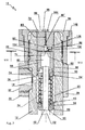
- the control body 72 is no longer seated in the tubular Housing 12, but is placed on the end face of this and through a corresponding recess in the further Union nut 94 held centrally and at the upper end of the tubular housing 12 pressed sealingly. center and runs through the control body 72 in the axial direction through the control passage 82; throttle inlet 92 is now in the slide valve body 64. He opens into the throttle passage 74 on the with respect to the narrowest cross section of the control body 72 facing side. The throttle inlet also communicates 92 via the recess 84, the gap 86 and the Flow gap 88 with the high pressure space 20.
- the slide valve body 64 shown in FIG. 6 is like 5 with another Throttle passage 122 and another stop shoulder 118 'equipped with the further counter stop shoulder 120 cooperates on the sleeve 58.
- Fig. 6 shows a further embodiment of the injection valve member 22, namely by the control piston 60 and the shaft 48 are formed as individual parts.
- the shaft 48 can also Penetrate control piston 60.
- the Projection 80 formed from the upper end of the shaft 48, and the control piston 60 is a sleeve with a continuous Bore that, as mentioned above, with shaft 48 can be put together.
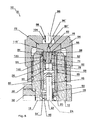
- the embodiment shown in Figs. 7, 8a and 8b also has a tubular housing 12 in which the Control body 72 is arranged fixed. With her the Control chamber 62 facing the end of the sleeve is supported 58, in which the double-acting control piston 60 of the Injector member 22 in a tight fit in the axial Direction is arranged, now sealing from and without hydraulic connection to the high pressure room 20. How described above is based on the sleeve 58 the side facing away from the control body 72, the Closing spring 46 for the injection valve member 22.
- the Control chamber 62 is thus on the one hand from control piston 60, circumferentially from the sleeve 58 and on the other hand from Control body 72 limited.
- the control body 72 points centrally and in the direction of Axis 24 extending the control passage 82, in which the radial throttle inlet 92 empties. This is due to milling on the outside 128 and the flow gap 88 between the sleeve 58 and the housing 12 connected to the high pressure space 20. Of the end face of the control body facing the control chamber 62 72 runs through this to the throttle inlet 92 Bore 130. This opens into the throttle inlet 92 on the with regard to the narrowest flow cross section High pressure room 20 side facing.
- Both the mouth of the control passage on the control room side 82 and those of the bore 130 are by means of a leaf spring-like tongue 132 covered, the shape of which 8a and 8b can be seen.
- the opposite end is the tongue 132 on the control body 72 welded.
- the welding point is labeled 134.
- the tongue 132 has a coaxial to the axis 24 Throttle passage 74, which the control chamber 62 with the Control passage 82 connects.
- Throttle restriction 82 'in the control passage 82 cross-sectionally larger than the narrowest cross-section of the Throttle inlet 92 and the cross section of the Throttle passage 74.
- the narrowest cross section 82 'of Control passage 82 has a bore 83 on the outlet side connected by a somewhat larger cross section.
- the bore 83 is preferably relatively long, compare with that Diameter, at least 2 to 10 times as long. So that will the flow after the narrowest cross section 82 'again fill in full, larger cross-section 83, which the Flow favored by the narrowest cross section 82 '. Otherwise the fuel injector is the same formed as shown in Figs. 1 to 4.
- the control device 26 according to FIGS. 7, 8a and 8b works like this.
- the pilot valve 104 is through Valve pin 98 abuts control body 72 closed.
- Valve pin 98 rests on electromagnet 100 Control body 72, whereby the control passage 82 from Low pressure room is separated.
- the pressure in the Control passage 82 which is due to the expansion of the Control passage and the pressure in the bore 130 for Bending the tongue 132 leads.
- the release of the Control passage 82 and the bore 130 now passes Fuel over a larger flow cross section in the control room 62, which leads to a rapid pressure increase in the Control room 62 and to move the Injection valve member 22 leads to the valve seat 44.
- the end face of the control piston 60 - or a head start - be designed so that at the end of the opening stroke, the throttle passage 74 is closed, and the pressure in the control chamber 62 is not or not quite at the lowest pressure in the Control passage 82 is adjusted.
- control piston 60 could be analogous to that in FIG Fig. 5 shown have a circumferential bead that with his stop shoulder and a counter stop shoulder cooperates to the stroke of the injection valve member 22 limit before the face of the spool 60 the Underside of the tongue 132 touched.
- FIGS. 9a and 9b show the same representation as that 8a and 8b a section VIII-VIII according to FIG. 7 and the tongue 132 in a different training form.
- the tongue 132 is integral with a retaining ring 136 formed.
- the retaining ring 136 is on at least one preferably at several points, for example at the with 134 designated welding points on the control body 72 welded.
- the leaf spring element according to FIG. 9b create yourself in a simple way by using a circular spring steel disc has a C-shaped groove is punched out. How the Fuel injector 10 with a control device 26 according to FIG. 7, but with an embodiment of the Tongue 132 according to FIGS. 9a and 9b is the same as that further above in connection with FIGS. 7, 8a and 8b . described
- FIG. 10 in conjunction with the 2 and 3a shows the electromagnet arrangement 16 a housing sleeve 138 with a molded on the inside circumferential ring 140 on.
- the ring 140 defines a contact surface 142 with which it is mounted Condition on a flat outer surface 144 of the others Union nut 94 abuts. This is the axial position of the electromagnet assembly 16 defined.
- One in axial Part 143 protruding over the contact surface 142 the housing sleeve 138 encompasses the further union nut 94, which also changes the radial position of the Electromagnet assembly 16 is defined.
- An O-ring 146 seals the low pressure space 106 from the environment.
- A runs around the further union nut 94 Threaded ring 148, on the one hand on a rotating Shoulder 149 of the further union nut 94 supports and on the other hand with its internal thread 149 'with a External thread 143 'screwed to the housing sleeve 138 is.
- the ring 140 is seated on the contact surface 142 facing away from an annular magnetic locking plate 150.
- This is supported in the axial direction Magnetic body 152 also designed as an annular body which on the magnetic closing plate 150 facing side an annular groove running around the axis 124 154 has.
- the coil 155 the via electrical coil connection conductor 156 - in the Fig. 10 only one is shown - with an electrical one Control device is connected.
- a holding body 158 On the the Magnetic closing plate 150 facing away from the Magnetic body 152 is a holding body 158, the can consist of an anti-magnetic material.
- the holding body 158 projects in the axial direction with a Stub 164 protrudes from the housing sleeve 138.
- the Stub 164 is the low pressure connection piece 110 be overcome.
- the anchor 102 has one on an anchor shaft 166 welded anchor ring 168 on, in the radial Direction seen within the magnetic closing plate 150 is arranged to form a narrow air gap.
- the anchor shaft 166 is in a stop sleeve 170 performed on the magnetic body 152 in the axial direction seen supported on a support shoulder 172.
- the Stop sleeve 170 is with the magnetic body 152 at 174, as shown, welded or crimped.
- the Stop sleeve 170 forms an axial stop for one ring shoulder 176 and ensures that between the anchor ring 168 and the Magnetic body 152 remains a gap when the armature 102 is attracted to the electromagnet 100.
- the armature 102 has one axially over the armature ring 168 Nose 182 protruding toward valve pin 98 which is intended to be used with the valve pin 98 to work together.
- the nose 182 has a transverse bore 184 on that in a blind hole 186 in the anchor shaft 166 flows.
- the anchor shaft 166 stands on the nose 182 opposite side with an end region in the axial direction about the stop sleeve 170. There is in the Anchor shaft 166 inserted a suppository 190 on which on the other hand, the armature spring 112 is supported.
- Anchor springs 112 is used to achieve high accuracy Injection processes necessary, the electromagnet arrangement 16 to calibrate. This is done by selecting one suitable suppository 190.
- suppositories 190 with different axial spacing of the surfaces, with which the suppository on the one hand on anchor shaft 166 and on the other hand, bear against the armature spring 112 posed.
- the contact surface serves as the basis for the measuring device 142.
- Replacement of suppositories 190 are to be ensured preferably both the largest outside diameter of the Suppository 190 as well as the outside diameter of the spring 112 smaller than the guide diameter of anchor shaft 166 in the stop sleeve 170.
- the length of the valve pin 98 can also be selected in Dependence on the stroke that the armature 102 is to travel.
- the outer surface 144 serves as the basis for measuring the Distance between this surface and the control body 72.
- the different embodiments of the Have fuel injector 10 according to the invention a slim build and offer a number of Possibilities to adapt the properties to the desired course of the injection process.
- the control devices 26 according to the invention can also with otherwise constructed differently Fuel injectors are used; so with Fuel injectors in which the fuel over a separate channel, and not coaxial with or on the axis 24 of the injector but laterally, in Housing is supplied to the valve seat element.
- the electromagnet arrangement shown and described and their attachment to the housing of the fuel injector can with different Fuel injectors are used.
- the tubular housing can also be used instead of a thread differently trained, well-known means of Attach an electromagnet assembly.
- a tubular housing with mounting options on the one hand for a valve seat element and on the other hand one Electromagnet arrangement and a connecting sleeve with High pressure connection spigots can also be different trained fuel injectors used become.
- An injection valve member, as described above, at that the shaft and the control piston as individual parts can be made at any Find fuel injectors.
Landscapes
- Engineering & Computer Science (AREA)
- Chemical & Material Sciences (AREA)
- Combustion & Propulsion (AREA)
- Mechanical Engineering (AREA)
- General Engineering & Computer Science (AREA)
- Physics & Mathematics (AREA)
- Fluid Mechanics (AREA)
- Fuel-Injection Apparatus (AREA)
Abstract
Description
- Fig. 1
- im Längsschnitt ein Brennstoffeinspritzventil;
- Fig. 2
- ebenfalls im Längsschnitt und bezüglich Fig. 1 vergrössert einen Teil des dort gezeigten Einspritzventils mit der Steuervorrichtung und der Elektromagnetanordnung;
- Fig. 3a
- einen Querschnitt durch das Einspritzventil der in Fig. 2 mit III-III bezeichnet ist;
- Fig. 3b
- in perspektivischer Darstellung Teile zur Abstützung der Schliessfeder des Brennstoffeinspritzventils;
- Fig. 4
- im Längsschnitt und bezüglich Fig. 1 und 2 vergrössert einen Teil des dort gezeigten Brennstoffeinspritzventils mit der Steuervorrichtung;
- Fig. 5
- in gleicher Darstellung wie Fig. 4 eine erste Ausbildungsform der erfindungsgemässen Steuervorrichtung;
- Fig. 6
- in gleicher Darstellung wie Fig. 4 und 5 eine zweite Ausbildungsform der erfindungsgemäss ausgebildeten Steuervorrichtung;
- Fig. 7
- in gleicher Darstellung wie Fig. 4, 5 und 6 eine Ausbildungsform der Steuervorrichtung für ein Einspritzventil, das anstelle eines Schieberventils ein Blattfederventil aufweist;
- Fig. 8a
- einen in der Fig. 7 mit VIII-VIII bezeichneten Querschnitt durch den dort gezeigten Teil des Brennstoffeininspritzventils;
- Fig. 8b
- in perspektivischer Darstellung die in der Steuervorrichtung gemäss den Fig. 7 und 8a verwendete Blattfeder;
- Fig. 9a
- in einem Schnitt entsprechend jenem der Fig. 8a eine weitere Ausbildungsform der Steuervorrichtung eines Einspritzventils mit einer Blattfeder;
- Fig. 9b
- in perspektivischer Darstellung das Blattfederelement beim Einspritzventil gemäss Fig. 9a; und
- Fig. 10
- im Längsschnitt und bezüglich Fig. 1 und 2 vergrössert einen Teil des dort gezeigten Brennstoffeinspritzventils mit der Elektromagnetanordnung.
Claims (6)
- Brennstoffeinspritzventil zur intermittierenden Brennstoffeinspritzung in den Brennraum einer Verbrennungskraftmaschine, mit einem einen Hochdruckeinlass (18) für den Brennstoff aufweisenden Gehäuse (12), einem zum Zusammenwirken mit einem Ventilsitzelement (14) bestimmten, im Gehäuse (12) längsbeweglich angeordneten und in Richtung gegen das Ventilsitzelement (14) federbelasteten Einspritzventilglied (22), einem am Einspritzventilglied (22) angeordneten, doppelwirkenden Steuerkolben (60), der einerseits einen mit dem Hochdruckeinlass (18) strömungsverbundenen Hochdruckraum (20) und andererseits einen Steuerraum (62) begrenzt, einem ebenfalls den Steuerraum (22) begrenzenden Steuerkörper (72) der einen vom Steuerraum (62) ausgehenden, über einen Drosseleinlass (92) mit dem Hochdruckraum (20) verbundenen und mittels eines Pilotventils (104) mit einem Niederdruckraum (106) verbindbaren Steuerdurchlass (82) aufweist, einem den Hochdruckraum (20) mit dem Steuerraum (62) verbindenden Zuströmkanal (130) mit einer eigenen Mündungsöffnung, und einem in Schliessstellung den Zuströmkanal (130) und den Steuerdurchlass (82) verschliessenden Ventilglied, das einen den Steuerraum (62) mit dem Steuerdurchlass (82) verbindenden Drosseldurchlass (74) aufweist, dadurch gekennzeichnet, dass das Ventilglied als eine einerends befestigte blattferderartige Zunge (132) ausgebildet ist.
- Brennstoffeinspritzventil nach Anspruch 1, dadurch gekennzeichnet, dass die Zunge am Steuerkörper (72) befestigt ist und im Ruhezustand an diesem anliegt.
- Brennstoffeinspritzventil nach Anspruch 1 oder 2, dadurch gekennzeichnet, dass die Zunge (132) an einem sie umgebenden Haltering (136) angeformt ist.
- Brennstoffeinspritzventil nach einem der Ansprüche 1 bis 3, dadurch gekennzeichnet, dass die Zunge (132) beziehungsweise der Haltering (136) am Steuerkörper (72) angeschweisst ist.
- Brennstoffeinspritzventil nach einem der Ansprüche 1 bis 4, dadurch gekennzeichnet, dass das Einspritzventilglied (22) eine als Spiralfeder ausgebildete Schliessfeder (46) durchgreift, die einerseits an einem, zwei auf dem Einspritzventilglied (22) sitzende Halbstützflansche (52) umgreifenden ersten Ring (54) und andererseits an einem einen einstückigen, einen Schlitz aufweisenden, gehäusefest abgestützten und zum Einspritzventilglied (22) umgreifenden zweiten Ring (54') abgestützt ist.
- Brennstoffeinspritzventil nach einem der Ansprüche 1 bis 5, dadurch gekennzeichnet, dass das Pilotventil (104) mittels einer in einer Gehäusehülse (138) angeordneten Elektromagnetanordnung (16) betätigt wird, und die Gehäusehülse (138) eine Anlagefläche (142) aufweist, mit welcher sie im montierten Zustand an einer gehäusefesten Aussenfläche (144) anliegt.
Applications Claiming Priority (3)
| Application Number | Priority Date | Filing Date | Title |
|---|---|---|---|
| CH12172001 | 2001-07-03 | ||
| CH12172001 | 2001-07-03 | ||
| EP02012798A EP1273791A3 (de) | 2001-07-03 | 2002-06-10 | Brennstoffeinspritzventil für Verbrennungskraftmaschinen |
Related Parent Applications (2)
| Application Number | Title | Priority Date | Filing Date |
|---|---|---|---|
| EP02012798A Division EP1273791A3 (de) | 2001-07-03 | 2002-06-10 | Brennstoffeinspritzventil für Verbrennungskraftmaschinen |
| EP02012798.1 Division | 2002-06-10 |
Publications (3)
| Publication Number | Publication Date |
|---|---|
| EP1431567A2 true EP1431567A2 (de) | 2004-06-23 |
| EP1431567A3 EP1431567A3 (de) | 2005-09-28 |
| EP1431567B1 EP1431567B1 (de) | 2010-06-02 |
Family
ID=4563506
Family Applications (2)
| Application Number | Title | Priority Date | Filing Date |
|---|---|---|---|
| EP04006794A Expired - Lifetime EP1431567B1 (de) | 2001-07-03 | 2002-06-10 | Brennstoffeinspritzventil für Verbrennungskraftmaschinen |
| EP02012798A Withdrawn EP1273791A3 (de) | 2001-07-03 | 2002-06-10 | Brennstoffeinspritzventil für Verbrennungskraftmaschinen |
Family Applications After (1)
| Application Number | Title | Priority Date | Filing Date |
|---|---|---|---|
| EP02012798A Withdrawn EP1273791A3 (de) | 2001-07-03 | 2002-06-10 | Brennstoffeinspritzventil für Verbrennungskraftmaschinen |
Country Status (6)
| Country | Link |
|---|---|
| US (1) | US6892967B2 (de) |
| EP (2) | EP1431567B1 (de) |
| JP (1) | JP4054621B2 (de) |
| AT (1) | ATE470065T1 (de) |
| DE (1) | DE50214476D1 (de) |
| ES (1) | ES2344695T3 (de) |
Cited By (2)
| Publication number | Priority date | Publication date | Assignee | Title |
|---|---|---|---|---|
| CH697562B1 (de) * | 2005-08-09 | 2008-11-28 | Ganser Hydromag | Brennstoffeinspritzventil. |
| WO2008148632A1 (de) | 2007-06-04 | 2008-12-11 | Robert Bosch Gmbh | Injektor mit steuerventil |
Families Citing this family (30)
| Publication number | Priority date | Publication date | Assignee | Title |
|---|---|---|---|---|
| EP1442209A1 (de) | 2001-11-09 | 2004-08-04 | Siemens Aktiengesellschaft | Steuermodul für einen injektor eines speichereinspritzsystems |
| ATE415554T1 (de) * | 2003-08-22 | 2008-12-15 | Ganser Hydromag | Pilotventil gesteuertes brennstoffeinspritzventil |
| ATE487057T1 (de) | 2004-02-25 | 2010-11-15 | Ganser Hydromag | Brennstoffeinspritzventil für verbrennungskraftmaschinen |
| EP1780406B1 (de) * | 2005-10-25 | 2011-01-05 | CRT Common Rail Technologies AG | Injektor für eine Kraftstoffeinspritzanlage sowie Kraftstoffeinspritzanlage mit einem solchen Injektor |
| RU2438035C2 (ru) * | 2006-03-03 | 2011-12-27 | Ганзер-Хюдромаг Аг | Инжекторный клапан для топлива для двигателя внутреннего сгорания (варианты) |
| JP2008138650A (ja) * | 2006-12-05 | 2008-06-19 | Denso Corp | 電磁弁およびそれを用いた燃料噴射装置 |
| US7779854B2 (en) * | 2007-01-12 | 2010-08-24 | Caterpillar Inc | Valve member to armature coupling system and fuel injector using same |
| DE102009000181A1 (de) * | 2009-01-13 | 2010-07-15 | Robert Bosch Gmbh | Kraftstoff-Injektor |
| DE102009007213B4 (de) * | 2009-02-03 | 2017-06-14 | Continental Automotive Gmbh | Injektorbaugruppe für ein Einspritzventil |
| JP5321472B2 (ja) * | 2009-06-02 | 2013-10-23 | 株式会社デンソー | 燃料噴射装置 |
| JP5493966B2 (ja) * | 2009-06-02 | 2014-05-14 | 株式会社デンソー | 燃料噴射装置 |
| US20110108010A1 (en) * | 2009-11-12 | 2011-05-12 | Aedc Alternative Energy Development Corporation | Fuel Vaporizing Device for Motor Vehicles and Method Therefor |
| JP5327117B2 (ja) * | 2010-03-24 | 2013-10-30 | 株式会社デンソー | 燃料噴射装置 |
| JP5625837B2 (ja) | 2010-03-31 | 2014-11-19 | 株式会社デンソー | 燃料噴射装置 |
| JP5304861B2 (ja) | 2010-12-17 | 2013-10-02 | 株式会社デンソー | 燃料噴射装置 |
| JP5310806B2 (ja) | 2011-01-07 | 2013-10-09 | 株式会社デンソー | 燃料噴射装置 |
| CN107061088B (zh) * | 2016-12-12 | 2019-09-03 | 中国第一汽车股份有限公司 | 一种新型共轨喷油器 |
| CN106762286B (zh) * | 2017-01-18 | 2023-03-21 | 哈尔滨工程大学 | 一种带液力反馈的微动态回油旁通式电控喷油器 |
| CN106762278B (zh) * | 2017-01-18 | 2023-03-21 | 哈尔滨工程大学 | 一种带液力反馈的微动态回油谐振旁通式电控喷油器 |
| CN106523223A (zh) * | 2017-01-18 | 2017-03-22 | 哈尔滨工程大学 | 一种微动态回油谐振旁通式电控喷油器 |
| CN106704066A (zh) * | 2017-01-18 | 2017-05-24 | 哈尔滨工程大学 | 一种微动态回油旁通式电控喷油器 |
| CN107165747B (zh) * | 2017-06-28 | 2023-06-09 | 哈尔滨工程大学 | 一种旁通式轴向进气的压电式内导向燃气喷射阀 |
| CN107061055B (zh) * | 2017-06-28 | 2023-05-30 | 哈尔滨工程大学 | 一种组合式双压电燃气喷射阀 |
| JP6962039B2 (ja) * | 2017-07-12 | 2021-11-05 | 株式会社デンソー | 燃料噴射装置 |
| CN108547717B (zh) * | 2018-02-08 | 2020-09-29 | 龙口龙泵燃油喷射有限公司 | 电控柴油喷射器 |
| CN108980365B (zh) * | 2018-09-10 | 2024-05-10 | 四川滨大阀门有限责任公司 | 一种高压差控制阀的阀内组件结构 |
| DE102018217761A1 (de) * | 2018-10-17 | 2020-04-23 | Robert Bosch Gmbh | Kraftstoffinjektor |
| WO2020260285A1 (de) | 2019-06-25 | 2020-12-30 | Ganser Hydromag Ag | Brennstoffeinspritzventil für verbrennungskraftmaschinen |
| JP7773978B2 (ja) * | 2019-12-03 | 2025-11-20 | ガンサー-ハイドロマグ アーゲー | 内燃機関用スライド弁を有する燃料噴射弁 |
| CN114790957B (zh) * | 2022-04-29 | 2023-11-21 | 中国北方发动机研究所(天津) | 一种滑阀式共轨喷油器 |
Family Cites Families (12)
| Publication number | Priority date | Publication date | Assignee | Title |
|---|---|---|---|---|
| DE3234829A1 (de) * | 1982-09-21 | 1984-03-22 | Deutsche Forschungs- und Versuchsanstalt für Luft- und Raumfahrt e.V., 5000 Köln | Einspritzvorrichtung fuer einen dieselmotor |
| EP0426205B1 (de) | 1985-12-02 | 1993-07-21 | Marco Alfredo Ganser | Steuereinrichtung für elektro-hydraulisch betätigte Kraftstoffeinspritzventile |
| EP0571003B1 (de) | 1987-12-02 | 1997-07-16 | Ganser-Hydromag Ag | Elektromagnetisch betätigbare Vorrichtung zum schnellen Umschalten eines elektro-hydraulisch betätigten Kraftstoffeinspritzventils |
| US5397055A (en) * | 1991-11-01 | 1995-03-14 | Paul; Marius A. | Fuel injector system |
| CH689282A5 (de) | 1994-03-29 | 1999-01-29 | Christian Dipl-Ing Eth Mathis | Einspritzventil fuer eine insbesondere als Dieselmotor vorgesehene Brennkraftmaschine. |
| US5636615A (en) * | 1995-02-21 | 1997-06-10 | Diesel Technology Company | Fuel pumping and injection systems |
| US5732679A (en) * | 1995-04-27 | 1998-03-31 | Isuzu Motors Limited | Accumulator-type fuel injection system |
| JP3555264B2 (ja) * | 1995-07-14 | 2004-08-18 | いすゞ自動車株式会社 | 内燃機関の燃料噴射装置 |
| DE19529826C1 (de) * | 1995-08-12 | 1996-12-12 | Mtu Friedrichshafen Gmbh | Einspritzventil für Common-Rail-Einspritzsysteme |
| JP2000018118A (ja) * | 1998-07-06 | 2000-01-18 | Isuzu Motors Ltd | インジェクタ |
| US6257496B1 (en) * | 1999-12-23 | 2001-07-10 | Siemens Automotive Corporation | Fuel injector having an integrated seat and swirl generator |
| EP1118765A3 (de) | 2000-01-19 | 2003-11-19 | CRT Common Rail Technologies AG | Brennstoffeinspritzventil für Verbrennungskraftmaschinen |
-
2002
- 2002-06-10 DE DE50214476T patent/DE50214476D1/de not_active Expired - Lifetime
- 2002-06-10 ES ES04006794T patent/ES2344695T3/es not_active Expired - Lifetime
- 2002-06-10 AT AT04006794T patent/ATE470065T1/de not_active IP Right Cessation
- 2002-06-10 EP EP04006794A patent/EP1431567B1/de not_active Expired - Lifetime
- 2002-06-10 EP EP02012798A patent/EP1273791A3/de not_active Withdrawn
- 2002-07-02 US US10/187,014 patent/US6892967B2/en not_active Expired - Lifetime
- 2002-07-03 JP JP2002194806A patent/JP4054621B2/ja not_active Expired - Fee Related
Cited By (3)
| Publication number | Priority date | Publication date | Assignee | Title |
|---|---|---|---|---|
| CH697562B1 (de) * | 2005-08-09 | 2008-11-28 | Ganser Hydromag | Brennstoffeinspritzventil. |
| WO2008148632A1 (de) | 2007-06-04 | 2008-12-11 | Robert Bosch Gmbh | Injektor mit steuerventil |
| DE102007025962A1 (de) | 2007-06-04 | 2008-12-11 | Robert Bosch Gmbh | Injektor mit Steuerventil |
Also Published As
| Publication number | Publication date |
|---|---|
| EP1431567B1 (de) | 2010-06-02 |
| ATE470065T1 (de) | 2010-06-15 |
| EP1431567A3 (de) | 2005-09-28 |
| JP2003035234A (ja) | 2003-02-07 |
| US20030052198A1 (en) | 2003-03-20 |
| EP1273791A2 (de) | 2003-01-08 |
| DE50214476D1 (de) | 2010-07-15 |
| EP1273791A3 (de) | 2003-03-12 |
| JP4054621B2 (ja) | 2008-02-27 |
| US6892967B2 (en) | 2005-05-17 |
| ES2344695T3 (es) | 2010-09-03 |
Similar Documents
| Publication | Publication Date | Title |
|---|---|---|
| EP1431567B1 (de) | Brennstoffeinspritzventil für Verbrennungskraftmaschinen | |
| DE69636585T2 (de) | Kraftstoffeinspritzdüse | |
| EP0745764B1 (de) | Brennstoffeinspritzventil für Verbrennungskraftmaschinen | |
| DE69918902T2 (de) | Brennstoffinjektor | |
| EP1476652B1 (de) | Brennstoffeinspritzventil für verbrennungskraftmaschinen | |
| EP1656498B1 (de) | Pilotventil gesteuertes brennstoffeinspritzventil | |
| EP3194757B1 (de) | Brennstoffeinspritzventil für verbrennungskraftmaschinen | |
| WO2007098621A1 (de) | Brennstoffeinspritzventil für verbrennungskraftmaschinen | |
| DE102005057526A1 (de) | Steuerventil und Kraftstoffeinspritzventil mit diesem | |
| EP1118765A2 (de) | Brennstoffeinspritzventil für Verbrennungskraftmaschinen | |
| DE10131201A1 (de) | Magnetventil zur Steuerung eines Einspritzventils einer Brennkraftmaschine | |
| EP0243931B1 (de) | Kraftstoffeinspritzvorrichtung für eine Brennkraftmaschine | |
| EP1771651B1 (de) | Kraftstoffinjektor mit direkter mehrstufiger einspritzventilgliedansteuerung | |
| EP2307697B1 (de) | Kraftstoffinjektor mit zweiteiligem magnetanker | |
| EP3990770A1 (de) | Brennstoffeinspritzventil für verbrennungskraftmaschinen | |
| DE60107794T2 (de) | Kraftstoffeinspritzsystem | |
| EP2102486A1 (de) | Injektor mit axial-druckausgeglichenem steuerventil | |
| DE10020867A1 (de) | Common-Rail-Injektor | |
| EP1718862B1 (de) | Brennstoffeinspritzventil für verbrennungskraftmaschinen | |
| EP1869311B1 (de) | Brennstoffeinspritzventil | |
| EP1373710B1 (de) | Kraftstoffeinspritzventil für brennkraftmaschinen | |
| DE10224689A1 (de) | Hubgesteuertes Ventil als Kraftstoffzumesseinrichtung eines Einspritzsystems für Brennkraftmaschinen | |
| DE10019153A1 (de) | Kraftstoffeinspritzventil für Brennkraftmaschinen | |
| DE102008000926A1 (de) | Kraftstoffinjektor mit Magnetventil | |
| EP1195516B1 (de) | Brennstoffeinspritzventil |
Legal Events
| Date | Code | Title | Description |
|---|---|---|---|
| PUAI | Public reference made under article 153(3) epc to a published international application that has entered the european phase |
Free format text: ORIGINAL CODE: 0009012 |
|
| AC | Divisional application: reference to earlier application |
Ref document number: 1273791 Country of ref document: EP Kind code of ref document: P |
|
| AK | Designated contracting states |
Kind code of ref document: A2 Designated state(s): AT BE CH CY DE DK ES FI FR GB GR IE IT LI LU MC NL PT SE TR |
|
| PUAL | Search report despatched |
Free format text: ORIGINAL CODE: 0009013 |
|
| AK | Designated contracting states |
Kind code of ref document: A3 Designated state(s): AT BE CH CY DE DK ES FI FR GB GR IE IT LI LU MC NL PT SE TR |
|
| 17P | Request for examination filed |
Effective date: 20060324 |
|
| AKX | Designation fees paid |
Designated state(s): AT BE CH CY DE DK ES FI FR GB GR IE IT LI LU MC NL PT SE TR |
|
| RAP1 | Party data changed (applicant data changed or rights of an application transferred) |
Owner name: CRT COMMON RAIL TECHNOLOGIES AG |
|
| GRAP | Despatch of communication of intention to grant a patent |
Free format text: ORIGINAL CODE: EPIDOSNIGR1 |
|
| GRAS | Grant fee paid |
Free format text: ORIGINAL CODE: EPIDOSNIGR3 |
|
| RIN1 | Information on inventor provided before grant (corrected) |
Inventor name: TAPPOLET, MARKUS Inventor name: GANSER, MARCO Inventor name: KOLB, ROLAND Inventor name: KERN, SEVERIN Inventor name: CARELLI, ANDREAS |
|
| GRAA | (expected) grant |
Free format text: ORIGINAL CODE: 0009210 |
|
| AC | Divisional application: reference to earlier application |
Ref document number: 1273791 Country of ref document: EP Kind code of ref document: P |
|
| AK | Designated contracting states |
Kind code of ref document: B1 Designated state(s): AT BE CH CY DE DK ES FI FR GB GR IE IT LI LU MC NL PT SE TR |
|
| REG | Reference to a national code |
Ref country code: GB Ref legal event code: FG4D Free format text: NOT ENGLISH |
|
| REG | Reference to a national code |
Ref country code: CH Ref legal event code: EP Ref country code: CH Ref legal event code: NV Representative=s name: RENTSCH & PARTNER |
|
| REG | Reference to a national code |
Ref country code: IE Ref legal event code: FG4D Free format text: LANGUAGE OF EP DOCUMENT: GERMAN |
|
| REF | Corresponds to: |
Ref document number: 50214476 Country of ref document: DE Date of ref document: 20100715 Kind code of ref document: P |
|
| PGFP | Annual fee paid to national office [announced via postgrant information from national office to epo] |
Ref country code: ES Payment date: 20100625 Year of fee payment: 9 |
|
| PGFP | Annual fee paid to national office [announced via postgrant information from national office to epo] |
Ref country code: AT Payment date: 20100614 Year of fee payment: 9 |
|
| REG | Reference to a national code |
Ref country code: ES Ref legal event code: FG2A Ref document number: 2344695 Country of ref document: ES Kind code of ref document: T3 |
|
| REG | Reference to a national code |
Ref country code: SE Ref legal event code: TRGR |
|
| REG | Reference to a national code |
Ref country code: NL Ref legal event code: VDEP Effective date: 20100602 |
|
| PG25 | Lapsed in a contracting state [announced via postgrant information from national office to epo] |
Ref country code: FI Free format text: LAPSE BECAUSE OF FAILURE TO SUBMIT A TRANSLATION OF THE DESCRIPTION OR TO PAY THE FEE WITHIN THE PRESCRIBED TIME-LIMIT Effective date: 20100602 |
|
| PGFP | Annual fee paid to national office [announced via postgrant information from national office to epo] |
Ref country code: SE Payment date: 20100614 Year of fee payment: 9 |
|
| BERE | Be: lapsed |
Owner name: CRT COMMON RAIL TECHNOLOGIES A.G. Effective date: 20100630 |
|
| PG25 | Lapsed in a contracting state [announced via postgrant information from national office to epo] |
Ref country code: GR Free format text: LAPSE BECAUSE OF FAILURE TO SUBMIT A TRANSLATION OF THE DESCRIPTION OR TO PAY THE FEE WITHIN THE PRESCRIBED TIME-LIMIT Effective date: 20100903 Ref country code: CY Free format text: LAPSE BECAUSE OF FAILURE TO SUBMIT A TRANSLATION OF THE DESCRIPTION OR TO PAY THE FEE WITHIN THE PRESCRIBED TIME-LIMIT Effective date: 20100602 |
|
| REG | Reference to a national code |
Ref country code: IE Ref legal event code: FD4D |
|
| PG25 | Lapsed in a contracting state [announced via postgrant information from national office to epo] |
Ref country code: MC Free format text: LAPSE BECAUSE OF NON-PAYMENT OF DUE FEES Effective date: 20100630 Ref country code: IE Free format text: LAPSE BECAUSE OF FAILURE TO SUBMIT A TRANSLATION OF THE DESCRIPTION OR TO PAY THE FEE WITHIN THE PRESCRIBED TIME-LIMIT Effective date: 20100602 Ref country code: NL Free format text: LAPSE BECAUSE OF FAILURE TO SUBMIT A TRANSLATION OF THE DESCRIPTION OR TO PAY THE FEE WITHIN THE PRESCRIBED TIME-LIMIT Effective date: 20100602 |
|
| PG25 | Lapsed in a contracting state [announced via postgrant information from national office to epo] |
Ref country code: PT Free format text: LAPSE BECAUSE OF FAILURE TO SUBMIT A TRANSLATION OF THE DESCRIPTION OR TO PAY THE FEE WITHIN THE PRESCRIBED TIME-LIMIT Effective date: 20101004 |
|
| PLBE | No opposition filed within time limit |
Free format text: ORIGINAL CODE: 0009261 |
|
| STAA | Information on the status of an ep patent application or granted ep patent |
Free format text: STATUS: NO OPPOSITION FILED WITHIN TIME LIMIT |
|
| PG25 | Lapsed in a contracting state [announced via postgrant information from national office to epo] |
Ref country code: DK Free format text: LAPSE BECAUSE OF FAILURE TO SUBMIT A TRANSLATION OF THE DESCRIPTION OR TO PAY THE FEE WITHIN THE PRESCRIBED TIME-LIMIT Effective date: 20100602 |
|
| 26N | No opposition filed |
Effective date: 20110303 |
|
| REG | Reference to a national code |
Ref country code: DE Ref legal event code: R097 Ref document number: 50214476 Country of ref document: DE Effective date: 20110302 |
|
| PG25 | Lapsed in a contracting state [announced via postgrant information from national office to epo] |
Ref country code: BE Free format text: LAPSE BECAUSE OF NON-PAYMENT OF DUE FEES Effective date: 20100630 |
|
| REG | Reference to a national code |
Ref country code: CH Ref legal event code: PFA Owner name: CRT COMMON RAIL TECHNOLOGIES AG Free format text: CRT COMMON RAIL TECHNOLOGIES AG#ANTHOPTSTRASSE 9 POSTFACH 97#8222 BERINGEN (CH) -TRANSFER TO- CRT COMMON RAIL TECHNOLOGIES AG#ANTHOPTSTRASSE 9 POSTFACH 97#8222 BERINGEN (CH) |
|
| REG | Reference to a national code |
Ref country code: SE Ref legal event code: EUG |
|
| PG25 | Lapsed in a contracting state [announced via postgrant information from national office to epo] |
Ref country code: AT Free format text: LAPSE BECAUSE OF NON-PAYMENT OF DUE FEES Effective date: 20110610 |
|
| REG | Reference to a national code |
Ref country code: AT Ref legal event code: MM01 Ref document number: 470065 Country of ref document: AT Kind code of ref document: T Effective date: 20110610 |
|
| REG | Reference to a national code |
Ref country code: ES Ref legal event code: FD2A Effective date: 20120717 |
|
| PG25 | Lapsed in a contracting state [announced via postgrant information from national office to epo] |
Ref country code: ES Free format text: LAPSE BECAUSE OF NON-PAYMENT OF DUE FEES Effective date: 20110611 |
|
| PG25 | Lapsed in a contracting state [announced via postgrant information from national office to epo] |
Ref country code: LU Free format text: LAPSE BECAUSE OF NON-PAYMENT OF DUE FEES Effective date: 20100610 |
|
| PG25 | Lapsed in a contracting state [announced via postgrant information from national office to epo] |
Ref country code: TR Free format text: LAPSE BECAUSE OF NON-PAYMENT OF DUE FEES Effective date: 20110610 |
|
| PGFP | Annual fee paid to national office [announced via postgrant information from national office to epo] |
Ref country code: TR Payment date: 20100610 Year of fee payment: 9 |
|
| PG25 | Lapsed in a contracting state [announced via postgrant information from national office to epo] |
Ref country code: SE Free format text: LAPSE BECAUSE OF NON-PAYMENT OF DUE FEES Effective date: 20110611 |
|
| REG | Reference to a national code |
Ref country code: FR Ref legal event code: PLFP Year of fee payment: 15 |
|
| PGFP | Annual fee paid to national office [announced via postgrant information from national office to epo] |
Ref country code: DE Payment date: 20160621 Year of fee payment: 15 Ref country code: GB Payment date: 20160621 Year of fee payment: 15 |
|
| PGFP | Annual fee paid to national office [announced via postgrant information from national office to epo] |
Ref country code: FR Payment date: 20160627 Year of fee payment: 15 |
|
| PGFP | Annual fee paid to national office [announced via postgrant information from national office to epo] |
Ref country code: IT Payment date: 20160628 Year of fee payment: 15 |
|
| REG | Reference to a national code |
Ref country code: CH Ref legal event code: PCAR Free format text: NEW ADDRESS: BELLERIVESTRASSE 203 POSTFACH, 8034 ZUERICH (CH) |
|
| REG | Reference to a national code |
Ref country code: DE Ref legal event code: R119 Ref document number: 50214476 Country of ref document: DE |
|
| GBPC | Gb: european patent ceased through non-payment of renewal fee |
Effective date: 20170610 |
|
| REG | Reference to a national code |
Ref country code: FR Ref legal event code: ST Effective date: 20180228 |
|
| PG25 | Lapsed in a contracting state [announced via postgrant information from national office to epo] |
Ref country code: GB Free format text: LAPSE BECAUSE OF NON-PAYMENT OF DUE FEES Effective date: 20170610 Ref country code: DE Free format text: LAPSE BECAUSE OF NON-PAYMENT OF DUE FEES Effective date: 20180103 |
|
| PG25 | Lapsed in a contracting state [announced via postgrant information from national office to epo] |
Ref country code: IT Free format text: LAPSE BECAUSE OF NON-PAYMENT OF DUE FEES Effective date: 20170610 Ref country code: FR Free format text: LAPSE BECAUSE OF NON-PAYMENT OF DUE FEES Effective date: 20170630 |
|
| PGFP | Annual fee paid to national office [announced via postgrant information from national office to epo] |
Ref country code: CH Payment date: 20201113 Year of fee payment: 19 |
|
| REG | Reference to a national code |
Ref country code: CH Ref legal event code: PL |
|
| PG25 | Lapsed in a contracting state [announced via postgrant information from national office to epo] |
Ref country code: LI Free format text: LAPSE BECAUSE OF NON-PAYMENT OF DUE FEES Effective date: 20210630 Ref country code: CH Free format text: LAPSE BECAUSE OF NON-PAYMENT OF DUE FEES Effective date: 20210630 |