EP1431585B1 - Pompe, en particulier pour un appareil ménager vehiculant de l'eau - Google Patents
Pompe, en particulier pour un appareil ménager vehiculant de l'eau Download PDFInfo
- Publication number
- EP1431585B1 EP1431585B1 EP20030028454 EP03028454A EP1431585B1 EP 1431585 B1 EP1431585 B1 EP 1431585B1 EP 20030028454 EP20030028454 EP 20030028454 EP 03028454 A EP03028454 A EP 03028454A EP 1431585 B1 EP1431585 B1 EP 1431585B1
- Authority
- EP
- European Patent Office
- Prior art keywords
- pump
- wall
- chamber
- sealing
- shaft
- Prior art date
- Legal status (The legal status is an assumption and is not a legal conclusion. Google has not performed a legal analysis and makes no representation as to the accuracy of the status listed.)
- Revoked
Links
Images



Classifications
-
- F—MECHANICAL ENGINEERING; LIGHTING; HEATING; WEAPONS; BLASTING
- F04—POSITIVE - DISPLACEMENT MACHINES FOR LIQUIDS; PUMPS FOR LIQUIDS OR ELASTIC FLUIDS
- F04D—NON-POSITIVE-DISPLACEMENT PUMPS
- F04D29/00—Details, component parts, or accessories
- F04D29/08—Sealings
- F04D29/10—Shaft sealings
- F04D29/106—Shaft sealings especially adapted for liquid pumps
-
- A—HUMAN NECESSITIES
- A47—FURNITURE; DOMESTIC ARTICLES OR APPLIANCES; COFFEE MILLS; SPICE MILLS; SUCTION CLEANERS IN GENERAL
- A47L—DOMESTIC WASHING OR CLEANING; SUCTION CLEANERS IN GENERAL
- A47L15/00—Washing or rinsing machines for crockery or tableware
- A47L15/42—Details
- A47L15/4214—Water supply, recirculation or discharge arrangements; Devices therefor
- A47L15/4225—Arrangements or adaption of recirculation or discharge pumps
Definitions
- the invention relates to a pump having a pump chamber and a drive shaft sealed in a wall of the pump chamber by means of a first radial shaft seal for pumping a liquid medium via an impeller rotating in the pump chamber.
- Such pumps are well known and come z. B. as submersible pumps or in water-conducting household appliances, such as in a washing machine or in a dishwasher, are used.
- a sealing ring with an adjoining spring such as a coil spring, used and secured against the direction of force of the spring in the wall of the pump chamber.
- a force is exerted in the radial direction, which must be absorbed by the wall.
- a shaft is sealed by arranged in a stuffing box chamber sealing elements.
- a separator ring and several soft packs are provided in the stuffing box chamber.
- a volume surrounding the shaft is formed. Passing through the separating ring and the wall of the stuffing box chamber, a bore is introduced for discharging or for flushing out of the pump chamber by the shaft seals leaking medium.
- DE 1 011 283 A also describes a sealing device for a drive shaft of a washing machine pump.
- a rotatably connected to the housing of the pump shaft seal is supported in the axial direction by a metal reinforcement, which has a grinding surface in the pump chamber facing away from, radially extending end face.
- a carbon loop is pressed by a spring over a flexible sleeve against the frontal grinding surface, wherein the spring, the flexible sleeve and the carbon slip ring are mounted on the shaft.
- FR 1.035.879 A and FR 67549E disclose a shaft seal for a pump with two elastic washers clamped between fixed washers, which abut against the shaft. In the space between the two elastic discs fat is stored.
- At least a second radial shaft sealing ring is present, which adjoins the first radial shaft sealing ring, wherein between the two radial shaft sealing rings surrounding the drive shaft chamber is present, which is also introduced into the wall of the pump housing.
- An advantage of the invention is that the sealing arrangement is free of forces in the axial direction of the pump shaft. There are only radial forces when, according to the invention, the sealing rings are press-fitted in the wall.
- the engine power has to be adapted to the hydraulic power only. This has the advantage that the electric power of the pump can be designed lower. Windings and laminated core thickness of the drive motor can be reduced. Overall, a higher efficiency of the pump is achieved by the invention.
- the pump is constructed so that a third radial shaft sealing ring is present, which adjoins the second sealing ring to form a chamber surrounding the shaft and is also introduced into the wall of the pump housing.
- a third radial shaft sealing ring is present, which adjoins the second sealing ring to form a chamber surrounding the shaft and is also introduced into the wall of the pump housing.
- the sealing rings each have a wall adjoining the wall extending in the radial direction in the axial direction, each forming a ring.
- sealing rings abut each other to form the chambers. This results from the mating of the sealing rings each annular or toroidal cavities or chambers that can be filled in whole or in part with a medium, in particular with oil.
- the chamber between the first and the second rotary shaft seal is at least partially filled by an at least temporarily liquid medium.
- the liquid medium reduces the friction of the shaft in the bearing in the wall.
- a fat in particular a food approved and at least in the warm pass, ie when heating and circulating the rinsing liquid at least partially liquefied fat used.
- a grease is used which gradually hardens after pumping out the rinsing liquid at the end of a wash program and in the off state of the dishwasher and changes from the at least partially liquid state into a solid state.
- the assembly process is simplified the introduction of the lubricant in at least one chamber formed by the radial shaft seal arrangement.
- the pump is also particularly suitable for use in household appliances that come into contact with food.
- An advantage is a pump in which the sealing rings each have a voltage applied to the shaft at an acute angle sealing lip which protrudes from the axial wall.
- the preferred steel combines the advantageous properties of magnetizability, corrosion resistance and hardenability, particularly noteworthy is the characteristic of the magnetizability of the shaft, which directly influences the yoke magnetization of the motor of the pump.
- a corrosion-free material is also essential because of the abrassive alkali attack of the washing liquid on the shaft.
- the sealing lips each have a shape which is also applicable to a grease scraper or oil scraper rings, e.g. Oil scraper chamfer ring is used.
- the seal with multiple radial shaft seals ensures that even if a sealing lip - for example, if the pump is a abrassives medium, eg. B. rinsing liquid, is pumped, worn, even a seal is made by the remaining sealing lip of the subsequent radial shaft seal.
- a abrassives medium eg. B. rinsing liquid
- the material used for the radial shaft seals any elastic material used, for example, an elastic plastic, but especially rubber, for example, a polyacrylonitrile-butadiene (NBR rubber).
- NBR rubber polyacrylonitrile-butadiene
- the same material is used for all sealing rings.
- the sealing ring which is arranged to the inside of the pump chamber, that is, the wear sealing ring, also a noted.
- the invention relates to a water-conducting household appliance with an array of sealing rings, which are formed, as described above with reference to the use in a pump.
- a seal construction is used for example for the drain pump of a washing machine or for the drain pump or the circulating pump in a dishwasher.
- the seal structure can also be used for the storage of the drive shaft of a laundry drum in the tub of a washing machine.
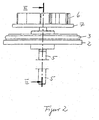
- a pump (Figs. 1 to 4) having a substantially cylindrical structure having a pump chamber has a completely enclosing wall.
- the wall comprises an end wall 2, which with a (not shown here) shell wall sealingly connected, for example by a welded or a screw connection.
- a sealing ring 3 may be present for sealing between the end wall 2 and the jacket wall.
- the end wall 2 has a central flange 4, passes through the centrally a drive shaft 5 for driving a pump blades 6 having impeller 7 passes.
- the drive shaft 5 is mounted via sealing rings 8, 9, 10 in the flange 4, the height of which is formed according to the height of the radial shaft seal formed by the sealing rings 8, 9, 10.
- the sealing rings 8, 9, 10 abut on its inner side on the outer jacket wall of the drive shaft 5, while resting on its outer side against an inner wall 40 of the flange 4.
- the sealing rings 8, 9, 10 each have a radially extending wall 120, 121 and 122 and a subsequent thereto and extending in the axial direction wall 130, 131 and 132nd on, so that the walls 120, 121, 122; 130, 131, 132 have a substantially L-shaped cross-section.
- each wall 120, 121, 122 each have a sealing lip 140, 141, 142 projecting integrally attached to the drive shaft 5.
- the sealing lips 140, 141, 142 in each case protrude against the jacket wall of the drive shaft 5 and are in contact therewith so that the sealing lips 140, 141, 142 have a large contact surface with drive shaft 5.
- the substantially V-shaped cross sections of the sealing lips 140, 141, 142 each have a pumpeschen leg which forms an obtuse angle with the jacket wall of the drive shaft, while the flange-side legs form an acute angle with the jacket wall of the drive shaft 5.
- the drive shaft has a very smooth surface at its contact surface for the sealing lips and is preferably ground, ie the surface also acts microscopically Non-promotional range ( ⁇ -range).
- the sealing rings 8, 9, 10 further have, below the walls 130, 131, 132, respectively projections 170, 171, 172, which cooperate with corresponding projections 180, 181, 182 on the upper side of the respective adjacent sealing ring 8, 9, 10.
- the interspaces are selected such that a substantially hermetic closure of the cavities or chambers 20, 21 lying between the sealing rings 8, 9, 10 is created by the interaction of the projections 170, 181.
- the chambers 20, 21 are either air, with a gas or at least partially with an at least temporarily liquid medium, d. H. suitable lubricant, preferably with a food-compatible fat, which at least partially liquefied in the warm passage of the dishwasher filled.
- the essentially hermetic closure ensures that the medium does not escape. So lapped z.
- the sealing lip 140 from below, the sealing lip 141 from above or the medium in chamber 21 flows around the sealing lip 141 from below and the sealing lip 142 from above and thus ensures a reduced friction between the drive shaft fifth and the sealing rings 8, 9, 10 during operation of the pump.
- By repeatedly washing off hardening and at least partially liquefying the lubricant is provided for a constant re-greasing at the contact surfaces of the output shaft and the sealing lips of the radial shaft seals and thereby increases the overall life.
- suitable lubricant and its changing state of aggregate from solid to liquid also loss of lubricant over the pores of the rubber material of the sealing rings is prevented over long periods.
Landscapes
- Engineering & Computer Science (AREA)
- Mechanical Engineering (AREA)
- General Engineering & Computer Science (AREA)
- Water Supply & Treatment (AREA)
- Structures Of Non-Positive Displacement Pumps (AREA)
Claims (9)
- Pompe avec une chambre de pompe et un arbre d'entraînement (5) rendu étanche dans une paroi (2) de la chambre de pompe au moyen d'une première bague d'étanchéité d'arbre radial (8) pour le pompage d'un milieu liquide par une roue de pompe (7) tournant dans la chambre de pompe, où au moins une deuxième bague d'étanchéité d'arbre radial (9) est prévue qui fait suite à la première bague d'étanchéité d'arbre radial (8),
entre les première et deuxième bagues d'étanchéité d'arbre radial (8, 9) est prévue une chambre (20) entourant l'arbre d'entraînement (5), qui est également disposée dans la paroi (2) de la chambre de pompe, et
au moins les deux bagues d'étanchéité d'arbre radial (8, 9) présentent des lèvres d'étanchéité (140, 141) s'appliquant à la paroi d'enveloppe extérieure de l'arbre d'entraînement (5),
caractérisée
en ce que les lèvres d'étanchéité (140, 141) s'appliquent d'une manière plane à la paroi d'enveloppe de l'arbre d'entraînement (5); et
en ce que la chambre (20) entre les première et deuxième bagues d'étanchéité d'arbre radial (8, 9) est remplie au moins partiellement par un lubrifiant liquide. - Pompe selon la revendication 1, caractérisée en ce qu'une troisième bague d'étanchéité d'arbre radial (10) est prévue qui, en réalisant une chambre (21) entourant l'arbre d'entraînement (5), fait suite à la deuxième bague d'étanchéité (9) et est également disposée dans la paroi (2) du carter de pompe.
- Pompe selon la revendication 2, caractérisée en ce que la chambre (21) entre la deuxième et la troisième bague d'étanchéité d'arbre radial (9, 10) est remplie au moins partiellement avec un lubrifiant liquide.
- Pompe selon la revendication 1, 2 ou 3, caractérisée en ce que le lubrifiant liquide est une graisse qui se liquéfie au moins lors du passage à chaud de la pompe, une huile, en particulier une huile peu visqueuse, acceptée comme aliment, ou une émulsion.
- Pompe selon l'une des revendications précédentes, caractérisée en ce que les bagues d'étanchéité (8, 9, 10) présentent à chaque fois une paroi sensiblement en forme de disque (120, 121, 122) s'étendant par rapport à l'arbre d'entraînement (5) dans la direction radiale.
- Pompe selon la revendication 5, caractérisée en ce que les bagues d'étanchéité (8, 9, 10) présentent à chaque fois une paroi (130, 131, 132) dans la direction axiale faisant suite à la paroi (120, 121, 122) s'étendant dans la direction radiale, qui forment à chaque fois une bague.
- Pompe selon la revendication 6, caractérisée en ce que les parois axiales (130, 131, 132) des bagues d'étanchéité (8, 9, 10), en formant les chambres (20, 21), s'appliquent les unes aux autres.
- Pompe selon l'une des revendications 1 à 7, caractérisée en ce que les bagues d'étanchéité d'arbre radial (8, 9, 10) présentent à chaque fois une lèvre d'étanchéité (140, 141, 142) s'appliquant selon un angle aigu à l'arbre d'entraînement (5), qui fait saillie de la paroi axiale.
- Appareil ménager utilisant de l'eau avec une pompe selon l'une des revendications 1 à 8.
Applications Claiming Priority (2)
| Application Number | Priority Date | Filing Date | Title |
|---|---|---|---|
| DE2002161160 DE10261160A1 (de) | 2002-12-20 | 2002-12-20 | Pumpe, insbesondere für ein wasserführendes Haushaltgerät |
| DE10261160 | 2002-12-20 |
Publications (2)
| Publication Number | Publication Date |
|---|---|
| EP1431585A1 EP1431585A1 (fr) | 2004-06-23 |
| EP1431585B1 true EP1431585B1 (fr) | 2006-03-01 |
Family
ID=32336609
Family Applications (1)
| Application Number | Title | Priority Date | Filing Date |
|---|---|---|---|
| EP20030028454 Revoked EP1431585B1 (fr) | 2002-12-20 | 2003-12-12 | Pompe, en particulier pour un appareil ménager vehiculant de l'eau |
Country Status (3)
| Country | Link |
|---|---|
| EP (1) | EP1431585B1 (fr) |
| DE (2) | DE10261160A1 (fr) |
| ES (1) | ES2259401T3 (fr) |
Families Citing this family (3)
| Publication number | Priority date | Publication date | Assignee | Title |
|---|---|---|---|---|
| DE102019126971A1 (de) * | 2019-10-08 | 2021-04-08 | Nidec Gpm Gmbh | Dampfleckagen-Kompaktdichtung |
| DE102020105781A1 (de) | 2020-03-04 | 2021-09-09 | Nidec Gpm Gmbh | Wasserpumpenlagereinheit mit Dichtungsanordnung sowie damit ausgerüstete Wasserpumpe |
| DE102020105771A1 (de) | 2020-03-04 | 2021-09-09 | Nidec Gpm Gmbh | Wasserpumpenlagereinheit mit sperrfluid-schmierstoff sowie damit ausgerüstete wasserpumpe |
Family Cites Families (6)
| Publication number | Priority date | Publication date | Assignee | Title |
|---|---|---|---|---|
| DE1011283B (de) * | 1954-06-23 | 1957-06-27 | Usines Jean Gallay Sa Des | Abdichtungseinrichtung fuer die Antriebswelle einer Zentrifugalpumpe zum Umwaelzen der Waschfluessigkeit in einer Waschmaschine |
| FR67549E (fr) * | 1955-02-08 | 1958-03-13 | Thomson Houston Comp Francaise | Pompe centrifuge perfectionnée à palettes |
| AT291777B (de) * | 1969-05-05 | 1971-07-26 | Vogel Pumpen | Wellendurchführung für Kreiselpumpen u.ähnl. Arbeitsmaschinen |
| DE4223544A1 (de) * | 1992-07-17 | 1994-01-20 | Kaco Gmbh Co | Pumpe, insbesondere Wasserpumpe, für Kraftfahrzeuge |
| JP2843280B2 (ja) * | 1995-09-29 | 1999-01-06 | アイシン精機株式会社 | ウォータポンプ |
| CA2288230A1 (fr) * | 1999-10-27 | 2001-04-27 | Thomas Wilson Ramsay | Cartouche a joints a levre multiples et manchon ajustable |
-
2002
- 2002-12-20 DE DE2002161160 patent/DE10261160A1/de not_active Withdrawn
-
2003
- 2003-12-12 ES ES03028454T patent/ES2259401T3/es not_active Expired - Lifetime
- 2003-12-12 EP EP20030028454 patent/EP1431585B1/fr not_active Revoked
- 2003-12-12 DE DE50302518T patent/DE50302518D1/de not_active Expired - Fee Related
Also Published As
| Publication number | Publication date |
|---|---|
| DE50302518D1 (de) | 2006-04-27 |
| ES2259401T3 (es) | 2006-10-01 |
| DE10261160A1 (de) | 2004-07-08 |
| EP1431585A1 (fr) | 2004-06-23 |
Similar Documents
| Publication | Publication Date | Title |
|---|---|---|
| EP1649169B1 (fr) | Pompe a moteur integre | |
| DE69629323T2 (de) | Permanentmagnetisch erregter Synchronmotor | |
| DE4343854C2 (de) | Magnetpumpe | |
| DE60125244T2 (de) | Monodirektionales Laufrad für elektrische Kreiselpumpen | |
| DE10251461A1 (de) | Elektrisch angetriebene Pumpe | |
| EP1987579A1 (fr) | Pompe centrifuge à moteur | |
| EP1502030A1 (fr) | Moteur de commande, notamment d'une pompe | |
| EP2505850B1 (fr) | Douille de palier | |
| EP2017479B1 (fr) | Fixation d'un palier radial dans un pot d'écartement d'une pompe | |
| DE102013100451B4 (de) | Rotor für Schnecken- und / oder Exzenterschneckenpumpen und Schnecken- oder Exzenterschneckenpumpe | |
| DE3534507A1 (de) | Brennkraftmaschine | |
| EP1567772A1 (fr) | Pompe a entrainement electrique | |
| EP1431585A1 (fr) | Pompe, en particulier pour un appareil ménager vehiculant de l'eau | |
| DE19525704C1 (de) | Gekapselter Rotor | |
| EP0854307B1 (fr) | Agencement pour réaliser l'étanchéité entre le rotor et le corps d'une pompe comprenant une garniture mécanique d'étanchéité | |
| DE102007025402B4 (de) | Pumpe für ein Haushaltsgerät | |
| DE2021775A1 (de) | Wellendurchfuehrung fuer Kreiselpumpen und aehnliche Arbeitsmaschinen | |
| DE3223236A1 (de) | Kraftstoffpumpe mit magnetantrieb | |
| EP1308624A1 (fr) | Pompe à moteur submersible | |
| EP1134420A2 (fr) | Pompe centrifuge avec structure de surface améliorant l'écoulement | |
| DE2639540A1 (de) | Gleitlagerhuelse fuer die pumpenwelle von umwaelzpumpen fuer heizungs- und brauchwasseranlagen | |
| EP0882891B1 (fr) | Pompe Moineau | |
| DE102007025403B4 (de) | Lagerschild zur Lagerung einer Welle | |
| DE102006011609B4 (de) | Drehschieberpumpe | |
| DE20014334U1 (de) | Pumpe |
Legal Events
| Date | Code | Title | Description |
|---|---|---|---|
| PUAI | Public reference made under article 153(3) epc to a published international application that has entered the european phase |
Free format text: ORIGINAL CODE: 0009012 |
|
| AK | Designated contracting states |
Kind code of ref document: A1 Designated state(s): AT BE BG CH CY CZ DE DK EE ES FI FR GB GR HU IE IT LI LU MC NL PT RO SE SI SK TR |
|
| AX | Request for extension of the european patent |
Extension state: AL LT LV MK |
|
| 17P | Request for examination filed |
Effective date: 20041130 |
|
| 17Q | First examination report despatched |
Effective date: 20050117 |
|
| AKX | Designation fees paid |
Designated state(s): DE ES FR GB IT SE |
|
| GRAP | Despatch of communication of intention to grant a patent |
Free format text: ORIGINAL CODE: EPIDOSNIGR1 |
|
| GRAS | Grant fee paid |
Free format text: ORIGINAL CODE: EPIDOSNIGR3 |
|
| GRAA | (expected) grant |
Free format text: ORIGINAL CODE: 0009210 |
|
| AK | Designated contracting states |
Kind code of ref document: B1 Designated state(s): DE ES FR GB IT SE |
|
| REG | Reference to a national code |
Ref country code: GB Ref legal event code: FG4D Free format text: NOT ENGLISH |
|
| REF | Corresponds to: |
Ref document number: 50302518 Country of ref document: DE Date of ref document: 20060427 Kind code of ref document: P |
|
| REG | Reference to a national code |
Ref country code: SE Ref legal event code: TRGR |
|
| GBT | Gb: translation of ep patent filed (gb section 77(6)(a)/1977) |
Effective date: 20060607 |
|
| REG | Reference to a national code |
Ref country code: ES Ref legal event code: FG2A Ref document number: 2259401 Country of ref document: ES Kind code of ref document: T3 |
|
| ET | Fr: translation filed | ||
| PGFP | Annual fee paid to national office [announced via postgrant information from national office to epo] |
Ref country code: DE Payment date: 20061212 Year of fee payment: 4 Ref country code: FR Payment date: 20061212 Year of fee payment: 4 |
|
| PGFP | Annual fee paid to national office [announced via postgrant information from national office to epo] |
Ref country code: ES Payment date: 20061215 Year of fee payment: 4 |
|
| PGFP | Annual fee paid to national office [announced via postgrant information from national office to epo] |
Ref country code: SE Payment date: 20061218 Year of fee payment: 4 |
|
| PLBI | Opposition filed |
Free format text: ORIGINAL CODE: 0009260 |
|
| PGFP | Annual fee paid to national office [announced via postgrant information from national office to epo] |
Ref country code: IT Payment date: 20061231 Year of fee payment: 4 |
|
| PLAF | Information modified related to communication of a notice of opposition and request to file observations + time limit |
Free format text: ORIGINAL CODE: EPIDOSCOBS2 |
|
| PLAX | Notice of opposition and request to file observation + time limit sent |
Free format text: ORIGINAL CODE: EPIDOSNOBS2 |
|
| 26 | Opposition filed |
Opponent name: KACO GMBH & CO. KG Effective date: 20061201 |
|
| PLBB | Reply of patent proprietor to notice(s) of opposition received |
Free format text: ORIGINAL CODE: EPIDOSNOBS3 |
|
| PLAY | Examination report in opposition despatched + time limit |
Free format text: ORIGINAL CODE: EPIDOSNORE2 |
|
| PLBC | Reply to examination report in opposition received |
Free format text: ORIGINAL CODE: EPIDOSNORE3 |
|
| EUG | Se: european patent has lapsed | ||
| GBPC | Gb: european patent ceased through non-payment of renewal fee |
Effective date: 20071212 |
|
| RDAF | Communication despatched that patent is revoked |
Free format text: ORIGINAL CODE: EPIDOSNREV1 |
|
| PG25 | Lapsed in a contracting state [announced via postgrant information from national office to epo] |
Ref country code: SE Free format text: LAPSE BECAUSE OF NON-PAYMENT OF DUE FEES Effective date: 20071213 Ref country code: DE Free format text: LAPSE BECAUSE OF NON-PAYMENT OF DUE FEES Effective date: 20080701 |
|
| RDAF | Communication despatched that patent is revoked |
Free format text: ORIGINAL CODE: EPIDOSNREV1 |
|
| REG | Reference to a national code |
Ref country code: FR Ref legal event code: ST Effective date: 20081020 |
|
| PG25 | Lapsed in a contracting state [announced via postgrant information from national office to epo] |
Ref country code: GB Free format text: LAPSE BECAUSE OF NON-PAYMENT OF DUE FEES Effective date: 20071212 |
|
| RDAG | Patent revoked |
Free format text: ORIGINAL CODE: 0009271 |
|
| STAA | Information on the status of an ep patent application or granted ep patent |
Free format text: STATUS: PATENT REVOKED |
|
| REG | Reference to a national code |
Ref country code: ES Ref legal event code: FD2A Effective date: 20071213 |
|
| 27W | Patent revoked |
Effective date: 20081110 |
|
| PG25 | Lapsed in a contracting state [announced via postgrant information from national office to epo] |
Ref country code: FR Free format text: LAPSE BECAUSE OF NON-PAYMENT OF DUE FEES Effective date: 20071231 |
|
| PG25 | Lapsed in a contracting state [announced via postgrant information from national office to epo] |
Ref country code: IT Free format text: LAPSE BECAUSE OF NON-PAYMENT OF DUE FEES Effective date: 20071212 |
|
| PG25 | Lapsed in a contracting state [announced via postgrant information from national office to epo] |
Ref country code: ES Free format text: LAPSE BECAUSE OF NON-PAYMENT OF DUE FEES Effective date: 20071213 |