EP1431609A2 - Amortisseur de vibrations de torsion - Google Patents
Amortisseur de vibrations de torsion Download PDFInfo
- Publication number
- EP1431609A2 EP1431609A2 EP03028788A EP03028788A EP1431609A2 EP 1431609 A2 EP1431609 A2 EP 1431609A2 EP 03028788 A EP03028788 A EP 03028788A EP 03028788 A EP03028788 A EP 03028788A EP 1431609 A2 EP1431609 A2 EP 1431609A2
- Authority
- EP
- European Patent Office
- Prior art keywords
- damping device
- torsional vibration
- vibration damping
- housing
- crankshaft
- Prior art date
- Legal status (The legal status is an assumption and is not a legal conclusion. Google has not performed a legal analysis and makes no representation as to the accuracy of the status listed.)
- Withdrawn
Links
Images






Classifications
-
- F—MECHANICAL ENGINEERING; LIGHTING; HEATING; WEAPONS; BLASTING
- F16—ENGINEERING ELEMENTS AND UNITS; GENERAL MEASURES FOR PRODUCING AND MAINTAINING EFFECTIVE FUNCTIONING OF MACHINES OR INSTALLATIONS; THERMAL INSULATION IN GENERAL
- F16F—SPRINGS; SHOCK-ABSORBERS; MEANS FOR DAMPING VIBRATION
- F16F15/00—Suppression of vibrations in systems; Means or arrangements for avoiding or reducing out-of-balance forces, e.g. due to motion
- F16F15/10—Suppression of vibrations in rotating systems by making use of members moving with the system
- F16F15/14—Suppression of vibrations in rotating systems by making use of members moving with the system using masses freely rotating with the system, i.e. uninvolved in transmitting driveline torque, e.g. rotative dynamic dampers
- F16F15/1407—Suppression of vibrations in rotating systems by making use of members moving with the system using masses freely rotating with the system, i.e. uninvolved in transmitting driveline torque, e.g. rotative dynamic dampers the rotation being limited with respect to the driving means
- F16F15/1414—Masses driven by elastic elements
- F16F15/1421—Metallic springs, e.g. coil or spiral springs
-
- F—MECHANICAL ENGINEERING; LIGHTING; HEATING; WEAPONS; BLASTING
- F16—ENGINEERING ELEMENTS AND UNITS; GENERAL MEASURES FOR PRODUCING AND MAINTAINING EFFECTIVE FUNCTIONING OF MACHINES OR INSTALLATIONS; THERMAL INSULATION IN GENERAL
- F16F—SPRINGS; SHOCK-ABSORBERS; MEANS FOR DAMPING VIBRATION
- F16F15/00—Suppression of vibrations in systems; Means or arrangements for avoiding or reducing out-of-balance forces, e.g. due to motion
- F16F15/22—Compensation of inertia forces
- F16F15/26—Compensation of inertia forces of crankshaft systems using solid masses, other than the ordinary pistons, moving with the system, i.e. masses connected through a kinematic mechanism or gear system
- F16F15/264—Rotating balancer shafts
-
- F—MECHANICAL ENGINEERING; LIGHTING; HEATING; WEAPONS; BLASTING
- F16—ENGINEERING ELEMENTS AND UNITS; GENERAL MEASURES FOR PRODUCING AND MAINTAINING EFFECTIVE FUNCTIONING OF MACHINES OR INSTALLATIONS; THERMAL INSULATION IN GENERAL
- F16F—SPRINGS; SHOCK-ABSORBERS; MEANS FOR DAMPING VIBRATION
- F16F15/00—Suppression of vibrations in systems; Means or arrangements for avoiding or reducing out-of-balance forces, e.g. due to motion
- F16F15/28—Counterweights, i.e. additional weights counterbalancing inertia forces induced by the reciprocating movement of masses in the system, e.g. of pistons attached to an engine crankshaft; Attaching or mounting same
- F16F15/283—Counterweights, i.e. additional weights counterbalancing inertia forces induced by the reciprocating movement of masses in the system, e.g. of pistons attached to an engine crankshaft; Attaching or mounting same for engine crankshafts
-
- Y—GENERAL TAGGING OF NEW TECHNOLOGICAL DEVELOPMENTS; GENERAL TAGGING OF CROSS-SECTIONAL TECHNOLOGIES SPANNING OVER SEVERAL SECTIONS OF THE IPC; TECHNICAL SUBJECTS COVERED BY FORMER USPC CROSS-REFERENCE ART COLLECTIONS [XRACs] AND DIGESTS
- Y10—TECHNICAL SUBJECTS COVERED BY FORMER USPC
- Y10T—TECHNICAL SUBJECTS COVERED BY FORMER US CLASSIFICATION
- Y10T74/00—Machine element or mechanism
- Y10T74/21—Elements
- Y10T74/2173—Cranks and wrist pins
- Y10T74/2183—Counterbalanced
- Y10T74/2184—Vibration dampers
Definitions
- the invention relates to a torsional vibration damping device, in particular one Cheek pads, for attachment to a crankshaft of a piston engine, in particular an internal combustion engine.
- the invention also relates to a crankshaft and a piston engine with a torsional vibration damping device.
- the object of the invention is therefore to provide a torsional vibration damping device, in particular to create a cheek eraser, of the type described at the outset, which is inexpensive can be produced.
- the task is in a torsional vibration damping device, in particular one Cheek pads, for attachment to a crankshaft of a piston engine, in particular an internal combustion engine, solved in that the torsional vibration damping device includes several sheet metal parts.
- the sheet metal parts provide the advantage that they are simple and are inexpensive to manufacture.
- the sheet metal parts can, for example, be drawn sheet metal be made. Individual areas of the sheet metal parts, such as holes or recesses, can be punched out. It is also possible to machine individual areas of the sheet metal parts to edit.
- a preferred embodiment of the torsional vibration damping device is thereby characterized in that the torsional vibration damping device is a housing comprises, which is attached to the crankshaft and with which, with the interposition of spring elements, at least one rotating mass is coupled.
- the Torsional vibration damping device can be preassembled. The pre-assembled torsional vibration damping device can then be mounted on the crankshaft in one step a piston engine are attached.
- the housing is essentially pot-shaped Shaped sheet metal part with a bottom that has a substantially rectangular recess which is open on one side.
- the recess serves the torsional vibration damping device form-fitting with a complementarily trained To connect the area of the crankshaft of a piston engine.
- Another preferred embodiment of the torsional vibration damping device is characterized in that on the housing in the region of the recess essentially circular segment-shaped approach is formed.
- the circular segment Approach is used to attach the torsional vibration damping device to the crankshaft a piston engine.
- Another preferred embodiment of the torsional vibration damping device is characterized in that in the circular segment-shaped approach at least a through hole is provided.
- the through hole is used to hold fasteners, like screws with which the torsional vibration damping device is attached the crankshaft of a piston engine can be attached.
- Another preferred embodiment of the torsional vibration damping device is characterized in that the bottom of the housing has a round edge, which is angled by 90 °. The angled or bent edge limits that Housing in the radial direction to the outside.
- the housing facing away from the floor Side can be closed by a lid which is formed by a sheet metal part.
- the outer contour the lid is preferably on the inner contour of the angled edge adapted to the case back.
- torsional vibration damping device is characterized in that the housing bottom and the housing cover by Spacers are attached to each other.
- the spacer bolts ensure one spaced arrangement of the two housing parts.
- the housing cover can also by a welded connection, for example on the bent edge of the floor be attached to the bottom of the case.
- torsional vibration damping device is characterized in that in the housing at least one flywheel is arranged, which is formed by at least one sheet metal part.
- the sheet metal part can Example by punching, inexpensive to manufacture.
- torsional vibration damping device is characterized in that at least on the flywheel radially outside a sliding element is attached.
- the sliding element serves to reduce the friction between the Flywheel and the housing, especially inside on the angled edge of the To minimize the case back.
- the sliding element is preferably made of Plastic formed.
- torsional vibration damping device is characterized in that in the case bottom, in the flywheel and at least one elongate recess is formed in the housing cover, which is arranged tangentially so that the recesses in the housing base, the Flywheel and the housing cover in the assembled state of the torsional vibration damping device aligned.
- the recesses serve to accommodate Compression springs through which the flywheel is coupled to the housing.
- Another preferred embodiment of the torsional vibration damping device is characterized in that through holes for Inclusion of balancing rivets are provided.
- the balancing rivets are in as needed different sizes and numbers attached to the case back.
- torsional vibration damping device is characterized in that the torsional vibration damping device in Is essentially horseshoe-shaped. This provides the advantage that the torsional vibration damping device Can be integrated into the crank arm of a crankshaft in a space-neutral manner is. This means that both the case base and the case cover are horseshoe-shaped.
- Torsional vibration damping devices also referred to as vibration absorbers can be used to, among other things, torsional natural frequencies of Suppress crankshafts. In many cases, such a natural frequency is in the range from approximately 300 to 450 Hz. This is particularly due to the non-uniformity as a result of the compression and expansion taking place in the pistons. On Swinging in the torsional resonance can lead to breakage of the crankshaft, which is why Torsional vibration damper or torsional vibration damper are used.
- the torsional vibration damping device is also called a torsional vibration damping device designated.
- a torsional vibration damping device with spring coupling basically consists of a rotating mass with a defined moment of inertia, the is connected to the crankshaft via spring elements. From the torsional stiffness of the spring elements and the moment of inertia of the rotating mass gives the natural frequency of the damper, which must be matched to the natural frequency of the crankshaft. Through the torsional vibration damping device, the vibration properties the crankshaft changed. The system receives an additional degree of freedom when damping The original resonance point disappears completely, but two new resonances occur on. With a very high damping there is no effect that is a damper quasi rigidly coupled, it shows approximately the basic resonance of the crankshaft. at Correct interpretation of the damping occurs neither the new nor the original resonances disruptive.
- a vibration damper 1 is shown, which has screws 2 and 3 is attached to a crankshaft 4.
- the vibration damper 1 is on the first Crank arm and is supported by the two radial screws 2 and the two axial screws 3 attached to the crankshaft and then together with this in the engine block built-in.
- the vibration damper 1 simultaneously replaces one of the counterweights Crankshaft 4.
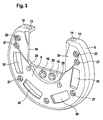
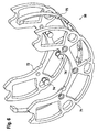
- FIGs 3 and 4 is a housing base 8, which is described in Figures 1 and 2 Vibration damping device 1 shown alone.
- the housing base 8 has essentially the shape of a circular disc, the edge 9 of which at an angle of approximately Is angled 90 °.
- At the angled edge 9 of the housing base 8 are two flats 10 and 11 formed in which through holes 13 and 14 are recessed are.
- the through holes 13 and 14 serve to carry out the in Figures 1 and 2 screws 2 shown, for fastening the torsional vibration damping device 1 serve on the crankshaft 4.
- the recess 16 is on one Open side and forms a form-fitting area that forms a positive connection between the housing base 8 and the crankshaft (not shown in FIGS. 3 and 4) allows.
- the rectangular recess 16 of a circular segment-shaped approach 18 in which two through holes 19 and 20 are provided.
- the through holes 19 and 20 serve to carry out the in the Figures 1 and 2 shown screws 3, which in turn for attaching the torsional vibration damper serve on the crankshaft.
- the housing base 8 shown in Figures 3 and 4 is formed from drawn sheet metal.
- the through holes 13, 14, 19, 20, 22, 23, 24, 25 and 27 and the windows 30 and the recess 16 were punched out of the drawn sheet metal.
- the areas 34 and 35 of the housing base 8 are machined.
- the housing base 8 also referred to as the housing pot can be closed by a housing cover 41, which is essentially one has a horseshoe shape.
- Four windows 43 are provided in the housing cover 41, which are congruent to the windows 30 in the housing base 8.
- the windows 43 are each between two through holes 45, 46; 46, 47; 47, 48 and 48, 49 arranged.
- the through holes 45 to 49 serve as well as the through holes 27 in the housing base 8, for receiving or fastening Spacer bolts 50 to 54.
- the spacer bolts 50 to 54 serve to cover the housing 41 to keep a defined distance from the housing base 8.
- FIG. 5 also shows balancing rivets 55 which, depending on requirements, in the through holes 22 and 23 can be attached in the housing base 8.
- the spacer bolts 50 to 54 between the housing base 8 and the housing cover 41 radially within the angled edge 9 of the housing base 8 Recording space created for a flywheel 56, which is also a horseshoe-shaped Has shape.
- the flywheel 56 is like the housing cover 41 to a stamped sheet metal part.
- Indentations 57 and 58 are provided for the spacer bolts 50 and 54.
- the dents 57 and 58 are dimensioned so that when assembled, the Torsional vibration damping device a rotation of the flywheel in the housing, that is formed by the housing base 8 and the housing cover 41 possible despite the presence of the spacer bolts 50 and 54.
- flywheel 56 In addition are in the flywheel 56 slots 59, 60 and 61 recessed through which in assembled state of the torsional vibration damping device the spacer bolts 51, 52 and 53 protrude.
- the slots 59 to 61 are dimensioned so that despite the presence of the spacer bolts 51 to 53, a rotary movement of the Flywheel 56 is possible in the housing.
- the flywheel 56 can be in one piece or be formed in several parts. In the present case, the flywheel comprises 56 several parts that are held together by rivets 63.
- the windows 30, 43 and 68 in the housing base 8, the housing cover 41 and the Inertia 56 are used to hold compression springs 65, which are guided through cups 66 are.
- the compression springs 65 are preloaded in the installed state and couple them Inertia 56 with the housing.
- the windows provided in the flywheel 56 68 have the same length, but a larger width than the windows 43 in the housing cover 41 and the windows 30 in the housing base 8.
- the smaller width of the Windows 43 and 30 prevent the compression springs 65 from passing through windows 30 and 43 can fall out of the housing.
- the width of windows 43 and 30 smaller than the diameter of the compression springs 65.
- the width of the window 68 in the Flywheel mass 56 is somewhat larger than the diameter of the compression springs 65.
- FIG. 6 shows that the flywheel 56 from FIG. 5 consists of a first sheet metal part 71 and a second sheet metal part 72 is formed.
- the two sheet metal parts 71 and 72 are held together by rivets 74, which correspond to the rivets 63 in FIG.
- Radial outside is a sliding element between or on the two sheet metal parts 71 and 72 75 attached from plastic, which is essentially the shape of a circular ring section having.
- the sliding element 75 comes in the installed state on the inside of the angled edge 9 of the housing base 8 for contact.
- the torsional vibration damping device is assembled Condition shown in different views.
- the generation of friction damping is done by combining the compression spring preload and the centrifugal force the flywheel mass or absorber mass.
- An additional, axial spring element can be provided to generate friction.
Landscapes
- Engineering & Computer Science (AREA)
- General Engineering & Computer Science (AREA)
- Physics & Mathematics (AREA)
- Acoustics & Sound (AREA)
- Aviation & Aerospace Engineering (AREA)
- Mechanical Engineering (AREA)
- Mechanical Operated Clutches (AREA)
- Shafts, Cranks, Connecting Bars, And Related Bearings (AREA)
- Vibration Prevention Devices (AREA)
Applications Claiming Priority (2)
| Application Number | Priority Date | Filing Date | Title |
|---|---|---|---|
| DE10258998 | 2002-12-16 | ||
| DE10258998 | 2002-12-16 |
Publications (2)
| Publication Number | Publication Date |
|---|---|
| EP1431609A2 true EP1431609A2 (fr) | 2004-06-23 |
| EP1431609A3 EP1431609A3 (fr) | 2006-06-07 |
Family
ID=32336402
Family Applications (1)
| Application Number | Title | Priority Date | Filing Date |
|---|---|---|---|
| EP03028788A Withdrawn EP1431609A3 (fr) | 2002-12-16 | 2003-12-13 | Amortisseur de vibrations de torsion |
Country Status (4)
| Country | Link |
|---|---|
| US (1) | US6883487B2 (fr) |
| EP (1) | EP1431609A3 (fr) |
| JP (1) | JP2004197944A (fr) |
| DE (1) | DE10358388A1 (fr) |
Families Citing this family (7)
| Publication number | Priority date | Publication date | Assignee | Title |
|---|---|---|---|---|
| EP1626199B1 (fr) * | 2004-08-11 | 2009-04-22 | LuK Lamellen und Kupplungsbau Beteiligungs KG | Amortisseur de vibrations torsionelles |
| EP1775496B1 (fr) | 2005-10-13 | 2013-11-06 | Schaeffler Technologies AG & Co. KG | Amortisseur de vibrations torsionelles |
| CN103671706A (zh) * | 2012-08-31 | 2014-03-26 | 弥荣(成都)实业有限公司 | 用于减小振动的调节装置 |
| CN205166525U (zh) | 2013-03-15 | 2016-04-20 | 通用电气公司 | 扭转频率调节器 |
| US9551398B2 (en) | 2013-03-15 | 2017-01-24 | General Electric Company | Torsional mode shifting |
| CN103883673A (zh) * | 2014-04-02 | 2014-06-25 | 广西玉柴机器股份有限公司 | 发动机的曲轴减振器 |
| US12305799B2 (en) * | 2023-04-19 | 2025-05-20 | National Products, Inc. | Vibration dampening mounts and methods of making and using |
Family Cites Families (4)
| Publication number | Priority date | Publication date | Assignee | Title |
|---|---|---|---|---|
| US2092571A (en) * | 1936-09-26 | 1937-09-07 | Gen Motors Corp | Vibration damper |
| US6142115A (en) | 1997-09-09 | 2000-11-07 | Luk Lamellen Und Kupplungsbau, Gmbh | Vibration damper for the crankshaft of a piston engine |
| DE19949206B4 (de) * | 1998-10-16 | 2009-04-02 | Luk Lamellen Und Kupplungsbau Beteiligungs Kg | Kolbenmotor mit Drehschwingungstilger sowie Drehschwingungstilger für einen Kolbenmotor |
| DE10039640B4 (de) * | 2000-08-09 | 2007-10-18 | Hasse & Wrede Gmbh | Gegengewicht mit viskos gedämpfter Sekundärmasse |
-
2003
- 2003-12-13 EP EP03028788A patent/EP1431609A3/fr not_active Withdrawn
- 2003-12-13 DE DE10358388A patent/DE10358388A1/de not_active Ceased
- 2003-12-15 JP JP2003416632A patent/JP2004197944A/ja not_active Withdrawn
- 2003-12-16 US US10/737,028 patent/US6883487B2/en not_active Expired - Lifetime
Also Published As
| Publication number | Publication date |
|---|---|
| US20040127295A1 (en) | 2004-07-01 |
| JP2004197944A (ja) | 2004-07-15 |
| DE10358388A1 (de) | 2004-06-24 |
| EP1431609A3 (fr) | 2006-06-07 |
| US6883487B2 (en) | 2005-04-26 |
Similar Documents
| Publication | Publication Date | Title |
|---|---|---|
| DE102004011830B4 (de) | Drehschwingungsdämpfer | |
| EP0777059B1 (fr) | Embrayage avec amortisseur de torsion | |
| DE69634788T2 (de) | Dämpfungsscheibeneinheit mit einem Reibungsmechanismus mit verbesserten Reibungselementen | |
| DE60223924T2 (de) | Kurbelwellendämpfer mit integrierter indexscheibe und herstellverfahren dafür | |
| DE19949206B4 (de) | Kolbenmotor mit Drehschwingungstilger sowie Drehschwingungstilger für einen Kolbenmotor | |
| DE112013004273T5 (de) | Kolbenstruktur für einen Motor | |
| EP0367988B1 (fr) | Pompe à membrane | |
| DE102015213653A1 (de) | Schwingungsdämpfer | |
| DE69823471T2 (de) | Schwingungsverzehrende Vorrichtung | |
| DE2617369B2 (de) | Gekapselter Motorverdichter für Kältemaschinen | |
| EP0503424B1 (fr) | Amatisseur de vibrations en torsion lié avec poulie | |
| DE102022123280A1 (de) | Zweimassenschwungrad | |
| EP1775496B1 (fr) | Amortisseur de vibrations torsionelles | |
| DE4212190A1 (de) | Elastische lagerung mit einer fluidfuellung | |
| EP3665401A1 (fr) | Amortisseur de vibrations torsionnelles à viscosité pour un vilebrequin d'un moteur à combustion interne | |
| EP1431609A2 (fr) | Amortisseur de vibrations de torsion | |
| EP1626199B1 (fr) | Amortisseur de vibrations torsionelles | |
| DE3700589C2 (de) | Schwingungsdämpfer | |
| DE19840217A1 (de) | Flexibles Schwungrad | |
| DE102014012747B4 (de) | Kolbenstruktur für Motor und Kolbenbolzen | |
| DE4110347C2 (de) | Befestigungsanordnung für eine Ablenkplatte in einem Motor | |
| DE102017120426A1 (de) | Pendel für kurbelwelle mit vollständig einstückigem stossfänger zur nvh-verbesserung | |
| DE102017004126A1 (de) | Drehschwingungsdämpfer | |
| DE4205764A1 (de) | Drehschwingungsdaempfer, insbesondere viskositaets-drehschwingungsdaempfer | |
| DE69811118T2 (de) | Schwingungsdämpfender ring für die radaufhängung eines kraftfahrzeuges |
Legal Events
| Date | Code | Title | Description |
|---|---|---|---|
| PUAI | Public reference made under article 153(3) epc to a published international application that has entered the european phase |
Free format text: ORIGINAL CODE: 0009012 |
|
| AK | Designated contracting states |
Kind code of ref document: A2 Designated state(s): AT BE BG CH CY CZ DE DK EE ES FI FR GB GR HU IE IT LI LU MC NL PT RO SE SI SK TR |
|
| AX | Request for extension of the european patent |
Extension state: AL LT LV MK |
|
| PUAL | Search report despatched |
Free format text: ORIGINAL CODE: 0009013 |
|
| AK | Designated contracting states |
Kind code of ref document: A3 Designated state(s): AT BE BG CH CY CZ DE DK EE ES FI FR GB GR HU IE IT LI LU MC NL PT RO SE SI SK TR |
|
| AX | Request for extension of the european patent |
Extension state: AL LT LV MK |
|
| 17P | Request for examination filed |
Effective date: 20061207 |
|
| AKX | Designation fees paid |
Designated state(s): AT BE BG CH CY CZ DE DK EE ES FI FR GB GR HU IE IT LI LU MC NL PT RO SE SI SK TR |
|
| 17Q | First examination report despatched |
Effective date: 20070220 |
|
| STAA | Information on the status of an ep patent application or granted ep patent |
Free format text: STATUS: THE APPLICATION IS DEEMED TO BE WITHDRAWN |
|
| 18D | Application deemed to be withdrawn |
Effective date: 20090701 |
|
| P01 | Opt-out of the competence of the unified patent court (upc) registered |
Effective date: 20230523 |