EP1431629A2 - Dispositif actionneur pour commander une tige de commande - Google Patents
Dispositif actionneur pour commander une tige de commande Download PDFInfo
- Publication number
- EP1431629A2 EP1431629A2 EP03027604A EP03027604A EP1431629A2 EP 1431629 A2 EP1431629 A2 EP 1431629A2 EP 03027604 A EP03027604 A EP 03027604A EP 03027604 A EP03027604 A EP 03027604A EP 1431629 A2 EP1431629 A2 EP 1431629A2
- Authority
- EP
- European Patent Office
- Prior art keywords
- piston
- shift rail
- rail
- adjusting device
- shift
- Prior art date
- Legal status (The legal status is an assumption and is not a legal conclusion. Google has not performed a legal analysis and makes no representation as to the accuracy of the status listed.)
- Granted
Links
- 239000002184 metal Substances 0.000 claims abstract description 8
- 239000004033 plastic Substances 0.000 claims abstract description 5
- 238000007789 sealing Methods 0.000 claims description 8
- 230000005540 biological transmission Effects 0.000 claims description 6
- 238000006073 displacement reaction Methods 0.000 description 3
- 238000004519 manufacturing process Methods 0.000 description 3
- 238000010276 construction Methods 0.000 description 2
- 238000000034 method Methods 0.000 description 2
- 241001295925 Gegenes Species 0.000 description 1
- 230000008878 coupling Effects 0.000 description 1
- 238000010168 coupling process Methods 0.000 description 1
- 238000005859 coupling reaction Methods 0.000 description 1
- 238000011161 development Methods 0.000 description 1
- 230000018109 developmental process Effects 0.000 description 1
- 230000009977 dual effect Effects 0.000 description 1
- 239000010720 hydraulic oil Substances 0.000 description 1
- 238000002347 injection Methods 0.000 description 1
- 239000007924 injection Substances 0.000 description 1
- 238000010409 ironing Methods 0.000 description 1
- 239000004636 vulcanized rubber Substances 0.000 description 1
Images


Classifications
-
- F—MECHANICAL ENGINEERING; LIGHTING; HEATING; WEAPONS; BLASTING
- F16—ENGINEERING ELEMENTS AND UNITS; GENERAL MEASURES FOR PRODUCING AND MAINTAINING EFFECTIVE FUNCTIONING OF MACHINES OR INSTALLATIONS; THERMAL INSULATION IN GENERAL
- F16C—SHAFTS; FLEXIBLE SHAFTS; ELEMENTS OR CRANKSHAFT MECHANISMS; ROTARY BODIES OTHER THAN GEARING ELEMENTS; BEARINGS
- F16C29/00—Bearings for parts moving only linearly
- F16C29/04—Ball or roller bearings
-
- F—MECHANICAL ENGINEERING; LIGHTING; HEATING; WEAPONS; BLASTING
- F15—FLUID-PRESSURE ACTUATORS; HYDRAULICS OR PNEUMATICS IN GENERAL
- F15B—SYSTEMS ACTING BY MEANS OF FLUIDS IN GENERAL; FLUID-PRESSURE ACTUATORS, e.g. SERVOMOTORS; DETAILS OF FLUID-PRESSURE SYSTEMS, NOT OTHERWISE PROVIDED FOR
- F15B15/00—Fluid-actuated devices for displacing a member from one position to another; Gearing associated therewith
- F15B15/08—Characterised by the construction of the motor unit
- F15B15/14—Characterised by the construction of the motor unit of the straight-cylinder type
- F15B15/1423—Component parts; Constructional details
- F15B15/1447—Pistons; Piston to piston rod assemblies
-
- F—MECHANICAL ENGINEERING; LIGHTING; HEATING; WEAPONS; BLASTING
- F16—ENGINEERING ELEMENTS AND UNITS; GENERAL MEASURES FOR PRODUCING AND MAINTAINING EFFECTIVE FUNCTIONING OF MACHINES OR INSTALLATIONS; THERMAL INSULATION IN GENERAL
- F16H—GEARING
- F16H63/00—Control outputs from the control unit to change-speed- or reversing-gearings for conveying rotary motion or to other devices than the final output mechanism
- F16H63/02—Final output mechanisms therefor; Actuating means for the final output mechanisms
- F16H63/30—Constructional features of the final output mechanisms
- F16H63/3023—Constructional features of the final output mechanisms the final output mechanisms comprising elements moved by fluid pressure
-
- F—MECHANICAL ENGINEERING; LIGHTING; HEATING; WEAPONS; BLASTING
- F16—ENGINEERING ELEMENTS AND UNITS; GENERAL MEASURES FOR PRODUCING AND MAINTAINING EFFECTIVE FUNCTIONING OF MACHINES OR INSTALLATIONS; THERMAL INSULATION IN GENERAL
- F16J—PISTONS; CYLINDERS; SEALINGS
- F16J1/00—Pistons; Trunk pistons; Plungers
- F16J1/10—Connection to driving members
- F16J1/14—Connection to driving members with connecting-rods, i.e. pivotal connections
- F16J1/22—Connection to driving members with connecting-rods, i.e. pivotal connections with universal joint, e.g. ball-joint
-
- F—MECHANICAL ENGINEERING; LIGHTING; HEATING; WEAPONS; BLASTING
- F16—ENGINEERING ELEMENTS AND UNITS; GENERAL MEASURES FOR PRODUCING AND MAINTAINING EFFECTIVE FUNCTIONING OF MACHINES OR INSTALLATIONS; THERMAL INSULATION IN GENERAL
- F16H—GEARING
- F16H63/00—Control outputs from the control unit to change-speed- or reversing-gearings for conveying rotary motion or to other devices than the final output mechanism
- F16H63/02—Final output mechanisms therefor; Actuating means for the final output mechanisms
- F16H63/30—Constructional features of the final output mechanisms
- F16H2063/3079—Shift rod assembly, e.g. supporting, assembly or manufacturing of shift rails or rods; Special details thereof
Definitions
- the invention relates to an actuating device for actuating a shift rail, in particular for a step change transmission of a motor vehicle, in which Change a gear the shift rail via one on the long side Hydraulic or pressurizable piston ends of the shift rail is pneumatically axially displaceable.
- a gear change is used Shift sleeve shifted with a shift fork.
- the shift fork is on one Shift rail or shift rod attached to their for easy movement Ends slide or preferably ball-bearing.
- the corridors exist a fixed gear and an idler gear. While the fixed gear with a gear shaft is rotatably connected, the idler gear is rotatably mounted on another gear shaft and to shift the gear in question via an associated, form-fitting Effective gear shift clutch can be connected to the other gear shaft in a rotationally fixed manner.
- the Gear shift clutch is lockable and separable via the shift sleeve, its actuation is realized by an axial displacement of the shift rail.
- a shift sleeve or Shift rails are assigned one or two gears depending on the type.
- the shift rail is mechanically operated with a shift finger postponed.
- Modern gears with a high number of gears and additional ones Transmission functions require a high level mechanical design effort.
- To reduce this effort increasingly automatically controllable hydraulic or pneumatic Actuators for actuating the gear functions, e.g. also to operate the Shift rail used.
- the piston is guided in a piston chamber and exercises during the switching process Pressure medium on the front side exerts a force on the shift rail that leads to the desired one leads to axial displacement.
- the piston usually seals over its diameter and prevents it from running empty provided with a sealing lip so that air in the piston chamber quickly escapes to the outside can.
- Such a connection between a piston and a shift rod is made of a known hydraulic actuator described in EP 1 164 316 A2.
- the piston has a recess for receiving one end of the Switch rod provided and has two lugs at the beginning of the recess, which in two assigned recesses of the shift rod are engaged.
- the piston has one Guide ring, which is guided in a cylinder bore of a gear housing. about the piston, the shift rod is shifted during a shift and in the Cylinder bore out. On a separate one arranged on the shift rail Guide bearings are dispensed with.
- a disadvantage of the known adjusting device is that the Snap connection in cooperation with the guide of the shift rod via the the piston firmly connected guide ring, a relatively rigid connection with a direct Force coupling between the piston and the shift rod represents.
- a Shifting are deformation forces that act as shear forces through the Shifting forces are exerted on the shift rod.
- These transverse forces act on the relatively rigid connection directly to the piston.
- unwanted Clamping forces occur that cause the shift rod to become stiff Cylinder bore with increased switching forces and increased wear. This is reinforced by the fact that the shift rail does not have its own guide bearing Relieves the piston.
- a shift rail is known from DE 201 20 394 U1, on the latter a piston-shaped bearing element is arranged at each end.
- the Piston elements are injection molded at the ends and form a firm connection to the Switching rail.
- a disadvantage is that the deformation forces arise due to the fixed connection the shift rail can act fully on the piston, creating high Clamping forces and high wear can occur. Furthermore, the fixed requires Connection an exact alignment of the two piston elements molded on the long side, which represents a high manufacturing outlay.
- the object of the present invention is therefore to so the known adjusting devices improve that they have a connection between a piston and a shift rail, which prevents detachment of the piston from the shift rail, in which one Transfer of deformation forces to the piston due to switching forces exercised on the shift rail when changing gears, largely avoided becomes.
- connection between the shift rail and the piston is flexible are compensating movements between the piston and shift rail, in particular radial relative movements possible.
- the piston can do not detach from the switching rail, i.e. in an undesirable manner regardless of the Adjust shift rail.
- the connection can be made via the movable properties also have elastic properties. Due to the variable possibilities of direct connection to the switching rail or indirect connection via the Guide bearing, which can be attached to the respective gear construction, with regard to the Available space, easy assembly and cost, cheapest connection can be realized.
- the adjusting device to the various common gear designs with a small space requirement and inexpensively adaptable and versatile.
- the connections via the guide bearing are particularly high Flexibility.
- the inner sleeve of the ball bearing can be particularly simple constructively with different connecting means, especially with lugs, Recesses, holding tabs, holding rakes or holding hooks with corresponding ones counterparts arranged on the piston interact. As a result, the shift rail is reliably held on the piston without a rigid connection between the shift rail and the piston is established.
- Spring elements are due to their elastic properties in a special way for one direct flexible connection of the piston to the shift rail is suitable.
- the piston will held by a spring clip on the shift rail, at the same time radial and axial relative movements between the piston and shift rail possible are more flexible compared to a direct snap connection.
- the flexible connection is designed as a dovetail connection in which a dovetail-shaped projection of the piston into a counterpart to that Projection formed recess on the shift rail is inserted laterally.
- the dovetail connection is particularly easy to manufacture and close assembly connection. There is sufficient scope, i.e. agility provided between the dovetail components to a corresponding To ensure mobility of the connection.
- the piston is designed as a plastic piston or as a sheet metal piston.
- the production of the plastic piston is particularly inexpensive. By selection wear-resistant plastic ensures a long service life.
- the sheet metal piston can be particularly easily with various connecting elements, such as brackets, Brackets rake or a bunch are formed.
- the piston body of the Sheet metal pistons can also be particularly advantageous as an element with elastic properties be trained to support the elasticity of the connection.
- An actuating device for actuating a shift rail 1 essentially consists of each a piston 2, which with the help of connecting means with the longitudinal ends of the Shift rail 1 connected by a flexible connection 15, 25, 35, 45, 55, 65, 75, 85 is.
- the two pistons 2 are used to push the shift rail 1 back and forth in the axial direction Direction. Both pistons 2 are arranged in mirror symmetry and have an identical structure, so that the description below is limited to a piston 2.
- the piston 2 is guided in a cylindrical piston chamber 5. It seals over its diameter and is against idling with a vulcanized circumferential sealing lip 6 Rubber. Air can escape from the piston chamber 5 via the sealing lip 6 escape.
- the shift rail 1 is made of a sheet metal part with a rectangular shape Cross section manufactured that at the ends with a guide bearing 3, advantageously as one Ball guide is formed, is ball-bearing, so that easy axial displacement the shift rail 1 is guaranteed.
- the ball guide 3 is in a manner known per se provided with an inner sleeve 4.
- the piston 2 can be pressurized can be moved hydraulically so that the shift rail is flexible Connection 15, 25, 35, 45, 55, 65, 75, 85 between the piston 2 and the shift rail 1 can be shifted axially in order to change gear without on the one hand, when the shift rail 1 is actuated, the piston 2 is moved by the shift rail 1 can replace, and on the other hand, the switching forces exerted on the shift rail 1 the piston 2 react undesirably.
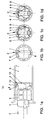
- FIGS. 1a-d A first embodiment of the invention with the connection 15 is shown in FIGS. 1a-d shown.
- the piston 2 is in the form of a cup 11 formed from sheet metal interrupted edge 7 formed.
- the rim 7 is towards the shift rail 1 towards curved inside.
- the shift rail 1 in turn has a front end at one end protruding edge 10 on.
- In the rim 7 there are two, at least that Cross-diameter of the edge 10 having recesses 8 is provided, in which the Shift rail 1 is inserted in a first assembly step.
- the bowl 11 is rotated by 90 °.
- the rim 7 surrounds the Rail edge 10.
- the interruptions of the rim 7 are in diameter smaller than the diameter of the rail edge 10.
- the Schienerand 10 In the rotated position, the Schienerand 10 thus held by the rim 7. At the same time, two are attacking the Inner sleeve 4, on the side facing the bowl 11 arranged lugs 9, in the now to the lugs 9 adjacent recesses 8 and secure the bowl 11 against one Back rotation.
- the piston 2 is movable with the shift rail 1 connected and at the same time against detachment when the shift rail 1 is actuated secured.
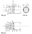
- FIGS. 2a-c A second embodiment of the invention with the connection 25 is shown in FIGS. 2a-c shown.
- the piston 2 is attached to the inner sleeve 4.
- On the inner sleeve 4 two retaining tabs 22 are arranged.
- the piston 2 is here as one, the cup 11 More similar, cup 20 is formed with an uninterrupted rim 21.
- the Retaining tabs 22 engage in the cup 20, causing the piston 2 against the inner sleeve 4, or is held against the shift rail 1.
- the figures show a third embodiment of the invention with the connection 35 3a + b.
- the piston 2 is in turn attached to the inner sleeve 4.
- two holding rakes 30 are formed, which are in the vulcanized rubber of the sealing lip 6 are raked.
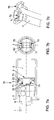
- FIGS. 4a-c A fourth embodiment of the invention with the connection 45 is shown in FIGS. 4a-c shown.
- the piston 2 is fastened to the inner sleeve 4.
- the piston 2 is off two sheets, an outer part 40 and an inner part 41, built.
- the inner part 41 is formed as an inwardly bent waistband.
- the outer part 40 detects one on the inside curved, adjacent to the switching rail 1, middle section.
- two holding hooks 42 are arranged adjacent to the collar.
- the assembly process takes place in two steps: First, the inner sleeve 4 is to the right moved and the piston hooked on one side with the upper hook 42 of the sleeve 4. Then the lower part is put on and the sleeve 4 is shifted to the left.
- the middle section of the outer part 40 comes with the end face of the switching rail 1 to concern and is axially preloaded. At the same time, the federal government and the Hook 42 the connection 45 radially centered.
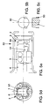
- FIGS. 5a-d A fifth embodiment of the invention with the connection 55 is shown in FIGS. 5a-d.
- a holding bracket 50 is welded to the piston 2.
- the holding clip 50 is suspended in two recesses 51 in the inner sleeve 4.
- connection 65 is an elastic fastening of the piston 2 the shift rail 1 with a spring element designed as a spring clip 60 executed.
- the annular spring clip 60 is in an interrupted edge 63 of the Piston 2 used.
- the piston 2 is in this embodiment, apart from the Not provided here recesses 8, identical in construction to the bowl 11.
- a bent End 61 of the spring clip 60 engages in a hole 62 in the shift rail 1, whereby the piston 2 is held elastically against the shift rail 1.
- connection 75 7a-c The connection 75 is based on the same principle as the connection 65.
- the spring element is designed as a double spring clip 70.
- the Double spring bracket 70 has two bracket parts 71 bent towards the shift rail 1 on which engage in two adjacent recesses 72 of the shift rail 1.
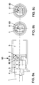
- connection 85 is a so-called Dovetail connection formed.
- the piston 2 is here with a sheet metal piston formed a dovetail-shaped projection 80.
- the projection 80 is at mounting laterally into a recess 81 in the switching rail 1 trained corresponding counterpart inserted.
- the recess 81 is from the side of the switching rail 1 up to a stop, i.e. not continuously, except. This results in an eccentric arrangement.
- a first Position Fig. 8 b
- the rail 1 is partially inserted laterally, in a second Position, rail 1 is pushed in as far as it will go and has its end position reached.
Landscapes
- Engineering & Computer Science (AREA)
- General Engineering & Computer Science (AREA)
- Mechanical Engineering (AREA)
- Physics & Mathematics (AREA)
- Fluid Mechanics (AREA)
- Chemical & Material Sciences (AREA)
- Combustion & Propulsion (AREA)
- Gear-Shifting Mechanisms (AREA)
Applications Claiming Priority (2)
| Application Number | Priority Date | Filing Date | Title |
|---|---|---|---|
| DE10260425A DE10260425A1 (de) | 2002-12-21 | 2002-12-21 | Stellvorrichtung zum Betätigen einer Schaltschiene |
| DE10260425 | 2002-12-21 |
Publications (3)
| Publication Number | Publication Date |
|---|---|
| EP1431629A2 true EP1431629A2 (fr) | 2004-06-23 |
| EP1431629A3 EP1431629A3 (fr) | 2005-09-07 |
| EP1431629B1 EP1431629B1 (fr) | 2008-02-20 |
Family
ID=32336560
Family Applications (1)
| Application Number | Title | Priority Date | Filing Date |
|---|---|---|---|
| EP03027604A Expired - Lifetime EP1431629B1 (fr) | 2002-12-21 | 2003-12-02 | Dispositif actionneur pour commander une tige de commande |
Country Status (4)
| Country | Link |
|---|---|
| EP (1) | EP1431629B1 (fr) |
| AT (1) | ATE386898T1 (fr) |
| DE (2) | DE10260425A1 (fr) |
| ES (1) | ES2298465T3 (fr) |
Cited By (1)
| Publication number | Priority date | Publication date | Assignee | Title |
|---|---|---|---|---|
| WO2009118160A3 (fr) * | 2008-03-26 | 2011-02-24 | Schaeffler Technologies Gmbh & Co. Kg | Palier à roulement linéaire et dispositif de commutation à palier à roulement linéaire |
Families Citing this family (6)
| Publication number | Priority date | Publication date | Assignee | Title |
|---|---|---|---|---|
| DE102005052454B4 (de) * | 2005-11-03 | 2019-03-14 | Schaeffler Technologies AG & Co. KG | Halterung für eine Schaltstange, Schaltstange mit einer Halterung, Getriebe und Verfahren zur Herstellung einer Halterung für eine Schaltstange |
| DE102007023715A1 (de) * | 2006-09-26 | 2008-04-03 | Schaeffler Kg | Schalteinrichtung, insbesondere für ein Wechselgetriebe eines Kraftfahrzeugs |
| DE102006045242A1 (de) * | 2006-09-26 | 2008-04-03 | Schaeffler Kg | Schalteinrichtung, insbesondere für ein Wechselgetriebe eines Kraftfahrzeugs, umfassend eine Schaltschiene |
| DE102006052239A1 (de) | 2006-11-03 | 2008-05-08 | Schaeffler Kg | Schalteinrichtung, insbesondere für ein Wechselgetriebe eines Kraftfahrzeugs, umfassend eine Schaltschiene |
| DE102008045658A1 (de) | 2008-09-03 | 2010-03-04 | Schaeffler Kg | Druckmittelbetätigte Schaltvorrichtung eines Stufenwechselgetriebes |
| DE102014204617A1 (de) | 2014-03-13 | 2015-09-17 | Zf Friedrichshafen Ag | Schaltvorrichtung eines automatisierten Schaltgetriebes |
Citations (2)
| Publication number | Priority date | Publication date | Assignee | Title |
|---|---|---|---|---|
| EP1164316A2 (fr) | 2000-06-09 | 2001-12-19 | FTE automotive GmbH | Actionneur hydraulique pour une tringle de commande d'une boíte de vitesse |
| DE20120394U1 (de) | 2001-11-30 | 2002-04-04 | Kochendörfer & Kiep Metallverarbeitung GmbH, 65830 Kriftel | Schaltgabel |
Family Cites Families (6)
| Publication number | Priority date | Publication date | Assignee | Title |
|---|---|---|---|---|
| DE1216630B (de) * | 1962-07-13 | 1966-05-12 | Westinghouse Bremsen Apparate | Arbeitskolben |
| DE2128982A1 (de) * | 1971-06-11 | 1973-01-04 | Demag Ag | Hydraulisch oder pneumatisch beaufschlagter arbeitszylinder |
| DE2914624C2 (de) * | 1979-04-11 | 1986-06-19 | Robert Bosch Gmbh, 7000 Stuttgart | Druckmittelbetätigter Arbeitszylinder |
| EP0061875A3 (fr) * | 1981-04-01 | 1983-09-21 | Automotive Products Public Limited Company | Mécanisme d'actionnement |
| US5442993A (en) * | 1994-01-13 | 1995-08-22 | United Technologies Corporation | Self-aligning piston |
| DE10041990B4 (de) * | 2000-08-26 | 2016-06-16 | Schaeffler Technologies AG & Co. KG | Wälzlager zur Führung einer Schaltschiene eines Getriebes |
-
2002
- 2002-12-21 DE DE10260425A patent/DE10260425A1/de not_active Withdrawn
-
2003
- 2003-12-02 ES ES03027604T patent/ES2298465T3/es not_active Expired - Lifetime
- 2003-12-02 EP EP03027604A patent/EP1431629B1/fr not_active Expired - Lifetime
- 2003-12-02 AT AT03027604T patent/ATE386898T1/de not_active IP Right Cessation
- 2003-12-02 DE DE50309196T patent/DE50309196D1/de not_active Expired - Lifetime
Patent Citations (2)
| Publication number | Priority date | Publication date | Assignee | Title |
|---|---|---|---|---|
| EP1164316A2 (fr) | 2000-06-09 | 2001-12-19 | FTE automotive GmbH | Actionneur hydraulique pour une tringle de commande d'une boíte de vitesse |
| DE20120394U1 (de) | 2001-11-30 | 2002-04-04 | Kochendörfer & Kiep Metallverarbeitung GmbH, 65830 Kriftel | Schaltgabel |
Cited By (1)
| Publication number | Priority date | Publication date | Assignee | Title |
|---|---|---|---|---|
| WO2009118160A3 (fr) * | 2008-03-26 | 2011-02-24 | Schaeffler Technologies Gmbh & Co. Kg | Palier à roulement linéaire et dispositif de commutation à palier à roulement linéaire |
Also Published As
| Publication number | Publication date |
|---|---|
| ES2298465T3 (es) | 2008-05-16 |
| DE10260425A1 (de) | 2004-07-22 |
| EP1431629A3 (fr) | 2005-09-07 |
| EP1431629B1 (fr) | 2008-02-20 |
| DE50309196D1 (de) | 2008-04-03 |
| ATE386898T1 (de) | 2008-03-15 |
Similar Documents
| Publication | Publication Date | Title |
|---|---|---|
| EP1647731B1 (fr) | Mécanisme de butée d'embrayage de séparation de véhicule automobile | |
| DE102021132824B3 (de) | Kupplung mit beidseitig unter Druck setzbarem Kolben und Kragarm aufweisendem Schnappverschluss | |
| DE69103239T2 (de) | Kupplungsausrücklager. | |
| EP2078879B1 (fr) | Dispositif de synchronisation pour boîte de vitesses | |
| DE102021132822B3 (de) | Kupplung mit beidseitig betätigbarem Kolben und mechanischen Rastierelementen | |
| EP1431629A2 (fr) | Dispositif actionneur pour commander une tige de commande | |
| WO2005036007A1 (fr) | Embrayage conçu pour une boite de vitesses | |
| DE10114844A1 (de) | Selbsteinstellendes Kupplungsausrücklager | |
| DE102021132819B3 (de) | Kupplung mit beidseitig beaufschlagbarem Kolben und Anschlagscheibe | |
| DE19926248B4 (de) | Gleitschuh eines Schaltelementes einer Schalteinrichtung | |
| EP1624212A1 (fr) | Dispositif de synchronisation | |
| EP1654472B1 (fr) | Element d'encliquetage | |
| EP1891347B1 (fr) | Butee d'embrayage de changement de vitesses | |
| DE102009056899B4 (de) | Kupplungsausrücksystem | |
| DE3621085A1 (de) | Synchronkupplung fuer getriebe | |
| DE102006060534A1 (de) | Synchronisiervorrichtung eines Wechselschaltgetriebes | |
| DE102022114373B3 (de) | Kopplungseinheit zum Koppeln und Entkoppeln zweier Antriebselemente eines Antriebsstrangs | |
| DE102021132821B3 (de) | Kupplung mit beidseitig beaufschlagbarem Kolben und axialelastischer Endanschlagscheibe für Schiebemuffe | |
| DE102006024084A1 (de) | Kupplungsausrücklager | |
| DE102018005150A1 (de) | Zentralausrücker für eine Kupplungsbetätigung | |
| DE102012204548A1 (de) | Betätigungsvorrichtung zur Betätigung von Kupplungseinrichtungen | |
| DE102010049935B4 (de) | Ventileinrichtung | |
| EP1694988B1 (fr) | Fourchette de boite de vitesses | |
| EP1703161A1 (fr) | Mécanisme d'actionnement pour embrayage d'un véhicule | |
| DE10246937A1 (de) | Halteclip für ein Kupplungsausrücklager |
Legal Events
| Date | Code | Title | Description |
|---|---|---|---|
| PUAI | Public reference made under article 153(3) epc to a published international application that has entered the european phase |
Free format text: ORIGINAL CODE: 0009012 |
|
| AK | Designated contracting states |
Kind code of ref document: A2 Designated state(s): AT BE BG CH CY CZ DE DK EE ES FI FR GB GR HU IE IT LI LU MC NL PT RO SE SI SK TR |
|
| AX | Request for extension of the european patent |
Extension state: AL LT LV MK |
|
| PUAL | Search report despatched |
Free format text: ORIGINAL CODE: 0009013 |
|
| RIC1 | Information provided on ipc code assigned before grant |
Ipc: 7F 16J 1/14 B Ipc: 7F 16H 63/30 A Ipc: 7F 15B 15/14 B Ipc: 7F 16J 1/22 B |
|
| AK | Designated contracting states |
Kind code of ref document: A3 Designated state(s): AT BE BG CH CY CZ DE DK EE ES FI FR GB GR HU IE IT LI LU MC NL PT RO SE SI SK TR |
|
| AX | Request for extension of the european patent |
Extension state: AL LT LV MK |
|
| 17P | Request for examination filed |
Effective date: 20060307 |
|
| AKX | Designation fees paid |
Designated state(s): AT BE BG CH CY CZ DE DK EE ES FI FR GB GR HU IE IT LI LU MC NL PT RO SE SI SK TR |
|
| 17Q | First examination report despatched |
Effective date: 20060601 |
|
| GRAP | Despatch of communication of intention to grant a patent |
Free format text: ORIGINAL CODE: EPIDOSNIGR1 |
|
| GRAS | Grant fee paid |
Free format text: ORIGINAL CODE: EPIDOSNIGR3 |
|
| GRAA | (expected) grant |
Free format text: ORIGINAL CODE: 0009210 |
|
| AK | Designated contracting states |
Kind code of ref document: B1 Designated state(s): AT BE BG CH CY CZ DE DK EE ES FI FR GB GR HU IE IT LI LU MC NL PT RO SE SI SK TR |
|
| REG | Reference to a national code |
Ref country code: GB Ref legal event code: FG4D Free format text: NOT ENGLISH |
|
| REG | Reference to a national code |
Ref country code: CH Ref legal event code: EP |
|
| REG | Reference to a national code |
Ref country code: IE Ref legal event code: FG4D Free format text: LANGUAGE OF EP DOCUMENT: GERMAN |
|
| REF | Corresponds to: |
Ref document number: 50309196 Country of ref document: DE Date of ref document: 20080403 Kind code of ref document: P |
|
| REG | Reference to a national code |
Ref country code: ES Ref legal event code: FG2A Ref document number: 2298465 Country of ref document: ES Kind code of ref document: T3 |
|
| PG25 | Lapsed in a contracting state [announced via postgrant information from national office to epo] |
Ref country code: FI Free format text: LAPSE BECAUSE OF FAILURE TO SUBMIT A TRANSLATION OF THE DESCRIPTION OR TO PAY THE FEE WITHIN THE PRESCRIBED TIME-LIMIT Effective date: 20080220 |
|
| NLV1 | Nl: lapsed or annulled due to failure to fulfill the requirements of art. 29p and 29m of the patents act | ||
| PG25 | Lapsed in a contracting state [announced via postgrant information from national office to epo] |
Ref country code: SI Free format text: LAPSE BECAUSE OF FAILURE TO SUBMIT A TRANSLATION OF THE DESCRIPTION OR TO PAY THE FEE WITHIN THE PRESCRIBED TIME-LIMIT Effective date: 20080220 |
|
| REG | Reference to a national code |
Ref country code: IE Ref legal event code: FD4D |
|
| PG25 | Lapsed in a contracting state [announced via postgrant information from national office to epo] |
Ref country code: CZ Free format text: LAPSE BECAUSE OF FAILURE TO SUBMIT A TRANSLATION OF THE DESCRIPTION OR TO PAY THE FEE WITHIN THE PRESCRIBED TIME-LIMIT Effective date: 20080220 Ref country code: IE Free format text: LAPSE BECAUSE OF FAILURE TO SUBMIT A TRANSLATION OF THE DESCRIPTION OR TO PAY THE FEE WITHIN THE PRESCRIBED TIME-LIMIT Effective date: 20080220 Ref country code: DK Free format text: LAPSE BECAUSE OF FAILURE TO SUBMIT A TRANSLATION OF THE DESCRIPTION OR TO PAY THE FEE WITHIN THE PRESCRIBED TIME-LIMIT Effective date: 20080220 Ref country code: NL Free format text: LAPSE BECAUSE OF FAILURE TO SUBMIT A TRANSLATION OF THE DESCRIPTION OR TO PAY THE FEE WITHIN THE PRESCRIBED TIME-LIMIT Effective date: 20080220 Ref country code: SK Free format text: LAPSE BECAUSE OF FAILURE TO SUBMIT A TRANSLATION OF THE DESCRIPTION OR TO PAY THE FEE WITHIN THE PRESCRIBED TIME-LIMIT Effective date: 20080220 Ref country code: PT Free format text: LAPSE BECAUSE OF FAILURE TO SUBMIT A TRANSLATION OF THE DESCRIPTION OR TO PAY THE FEE WITHIN THE PRESCRIBED TIME-LIMIT Effective date: 20080721 Ref country code: SE Free format text: LAPSE BECAUSE OF FAILURE TO SUBMIT A TRANSLATION OF THE DESCRIPTION OR TO PAY THE FEE WITHIN THE PRESCRIBED TIME-LIMIT Effective date: 20080520 |
|
| PG25 | Lapsed in a contracting state [announced via postgrant information from national office to epo] |
Ref country code: RO Free format text: LAPSE BECAUSE OF FAILURE TO SUBMIT A TRANSLATION OF THE DESCRIPTION OR TO PAY THE FEE WITHIN THE PRESCRIBED TIME-LIMIT Effective date: 20080220 |
|
| EN | Fr: translation not filed | ||
| PLBE | No opposition filed within time limit |
Free format text: ORIGINAL CODE: 0009261 |
|
| STAA | Information on the status of an ep patent application or granted ep patent |
Free format text: STATUS: NO OPPOSITION FILED WITHIN TIME LIMIT |
|
| 26N | No opposition filed |
Effective date: 20081121 |
|
| PG25 | Lapsed in a contracting state [announced via postgrant information from national office to epo] |
Ref country code: BG Free format text: LAPSE BECAUSE OF FAILURE TO SUBMIT A TRANSLATION OF THE DESCRIPTION OR TO PAY THE FEE WITHIN THE PRESCRIBED TIME-LIMIT Effective date: 20080520 Ref country code: EE Free format text: LAPSE BECAUSE OF FAILURE TO SUBMIT A TRANSLATION OF THE DESCRIPTION OR TO PAY THE FEE WITHIN THE PRESCRIBED TIME-LIMIT Effective date: 20080220 Ref country code: FR Free format text: LAPSE BECAUSE OF FAILURE TO SUBMIT A TRANSLATION OF THE DESCRIPTION OR TO PAY THE FEE WITHIN THE PRESCRIBED TIME-LIMIT Effective date: 20081212 |
|
| BERE | Be: lapsed |
Owner name: VOLKSWAGEN A.G. Effective date: 20081231 |
|
| PG25 | Lapsed in a contracting state [announced via postgrant information from national office to epo] |
Ref country code: MC Free format text: LAPSE BECAUSE OF NON-PAYMENT OF DUE FEES Effective date: 20081231 Ref country code: CY Free format text: LAPSE BECAUSE OF FAILURE TO SUBMIT A TRANSLATION OF THE DESCRIPTION OR TO PAY THE FEE WITHIN THE PRESCRIBED TIME-LIMIT Effective date: 20080220 |
|
| REG | Reference to a national code |
Ref country code: CH Ref legal event code: PL |
|
| GBPC | Gb: european patent ceased through non-payment of renewal fee |
Effective date: 20081202 |
|
| PG25 | Lapsed in a contracting state [announced via postgrant information from national office to epo] |
Ref country code: IT Free format text: LAPSE BECAUSE OF FAILURE TO SUBMIT A TRANSLATION OF THE DESCRIPTION OR TO PAY THE FEE WITHIN THE PRESCRIBED TIME-LIMIT Effective date: 20080220 |
|
| PG25 | Lapsed in a contracting state [announced via postgrant information from national office to epo] |
Ref country code: BE Free format text: LAPSE BECAUSE OF NON-PAYMENT OF DUE FEES Effective date: 20081231 |
|
| PG25 | Lapsed in a contracting state [announced via postgrant information from national office to epo] |
Ref country code: CH Free format text: LAPSE BECAUSE OF NON-PAYMENT OF DUE FEES Effective date: 20081231 Ref country code: LI Free format text: LAPSE BECAUSE OF NON-PAYMENT OF DUE FEES Effective date: 20081231 |
|
| PG25 | Lapsed in a contracting state [announced via postgrant information from national office to epo] |
Ref country code: GB Free format text: LAPSE BECAUSE OF NON-PAYMENT OF DUE FEES Effective date: 20081202 |
|
| PG25 | Lapsed in a contracting state [announced via postgrant information from national office to epo] |
Ref country code: AT Free format text: LAPSE BECAUSE OF NON-PAYMENT OF DUE FEES Effective date: 20081202 |
|
| PG25 | Lapsed in a contracting state [announced via postgrant information from national office to epo] |
Ref country code: LU Free format text: LAPSE BECAUSE OF NON-PAYMENT OF DUE FEES Effective date: 20081202 Ref country code: HU Free format text: LAPSE BECAUSE OF FAILURE TO SUBMIT A TRANSLATION OF THE DESCRIPTION OR TO PAY THE FEE WITHIN THE PRESCRIBED TIME-LIMIT Effective date: 20080821 |
|
| PG25 | Lapsed in a contracting state [announced via postgrant information from national office to epo] |
Ref country code: TR Free format text: LAPSE BECAUSE OF FAILURE TO SUBMIT A TRANSLATION OF THE DESCRIPTION OR TO PAY THE FEE WITHIN THE PRESCRIBED TIME-LIMIT Effective date: 20080220 |
|
| PG25 | Lapsed in a contracting state [announced via postgrant information from national office to epo] |
Ref country code: GR Free format text: LAPSE BECAUSE OF FAILURE TO SUBMIT A TRANSLATION OF THE DESCRIPTION OR TO PAY THE FEE WITHIN THE PRESCRIBED TIME-LIMIT Effective date: 20080521 |
|
| PGFP | Annual fee paid to national office [announced via postgrant information from national office to epo] |
Ref country code: ES Payment date: 20160121 Year of fee payment: 13 Ref country code: DE Payment date: 20151231 Year of fee payment: 13 |
|
| REG | Reference to a national code |
Ref country code: DE Ref legal event code: R119 Ref document number: 50309196 Country of ref document: DE |
|
| PG25 | Lapsed in a contracting state [announced via postgrant information from national office to epo] |
Ref country code: DE Free format text: LAPSE BECAUSE OF NON-PAYMENT OF DUE FEES Effective date: 20170701 |
|
| PG25 | Lapsed in a contracting state [announced via postgrant information from national office to epo] |
Ref country code: ES Free format text: LAPSE BECAUSE OF NON-PAYMENT OF DUE FEES Effective date: 20161203 |
|
| REG | Reference to a national code |
Ref country code: ES Ref legal event code: FD2A Effective date: 20180626 |