EP1431655A2 - Leuchte - Google Patents
Leuchte Download PDFInfo
- Publication number
- EP1431655A2 EP1431655A2 EP03029042A EP03029042A EP1431655A2 EP 1431655 A2 EP1431655 A2 EP 1431655A2 EP 03029042 A EP03029042 A EP 03029042A EP 03029042 A EP03029042 A EP 03029042A EP 1431655 A2 EP1431655 A2 EP 1431655A2
- Authority
- EP
- European Patent Office
- Prior art keywords
- light
- outer body
- luminaire according
- gap
- wall
- Prior art date
- Legal status (The legal status is an assumption and is not a legal conclusion. Google has not performed a legal analysis and makes no representation as to the accuracy of the status listed.)
- Withdrawn
Links
- 230000003287 optical effect Effects 0.000 claims description 7
- 230000000694 effects Effects 0.000 description 7
- 229910052736 halogen Inorganic materials 0.000 description 6
- 150000002367 halogens Chemical class 0.000 description 6
- 229910052751 metal Inorganic materials 0.000 description 6
- 239000002184 metal Substances 0.000 description 6
- 238000011161 development Methods 0.000 description 2
- 230000018109 developmental process Effects 0.000 description 2
- 238000005516 engineering process Methods 0.000 description 2
- 229910000838 Al alloy Inorganic materials 0.000 description 1
- 239000000853 adhesive Substances 0.000 description 1
- 238000010276 construction Methods 0.000 description 1
- 230000001419 dependent effect Effects 0.000 description 1
- 238000005265 energy consumption Methods 0.000 description 1
- 230000002349 favourable effect Effects 0.000 description 1
- 230000017525 heat dissipation Effects 0.000 description 1
- 238000005286 illumination Methods 0.000 description 1
- 239000000463 material Substances 0.000 description 1
- 238000012986 modification Methods 0.000 description 1
- 230000004048 modification Effects 0.000 description 1
- NJPPVKZQTLUDBO-UHFFFAOYSA-N novaluron Chemical compound C1=C(Cl)C(OC(F)(F)C(OC(F)(F)F)F)=CC=C1NC(=O)NC(=O)C1=C(F)C=CC=C1F NJPPVKZQTLUDBO-UHFFFAOYSA-N 0.000 description 1
- 238000009423 ventilation Methods 0.000 description 1
Images


Classifications
-
- F—MECHANICAL ENGINEERING; LIGHTING; HEATING; WEAPONS; BLASTING
- F21—LIGHTING
- F21V—FUNCTIONAL FEATURES OR DETAILS OF LIGHTING DEVICES OR SYSTEMS THEREOF; STRUCTURAL COMBINATIONS OF LIGHTING DEVICES WITH OTHER ARTICLES, NOT OTHERWISE PROVIDED FOR
- F21V14/00—Controlling the distribution of the light emitted by adjustment of elements
- F21V14/08—Controlling the distribution of the light emitted by adjustment of elements by movement of the screens or filters
-
- F—MECHANICAL ENGINEERING; LIGHTING; HEATING; WEAPONS; BLASTING
- F21—LIGHTING
- F21V—FUNCTIONAL FEATURES OR DETAILS OF LIGHTING DEVICES OR SYSTEMS THEREOF; STRUCTURAL COMBINATIONS OF LIGHTING DEVICES WITH OTHER ARTICLES, NOT OTHERWISE PROVIDED FOR
- F21V11/00—Screens not covered by groups F21V1/00, F21V3/00, F21V7/00 or F21V9/00
- F21V11/08—Screens not covered by groups F21V1/00, F21V3/00, F21V7/00 or F21V9/00 using diaphragms containing one or more apertures
- F21V11/12—Screens not covered by groups F21V1/00, F21V3/00, F21V7/00 or F21V9/00 using diaphragms containing one or more apertures of slot type
Definitions
- the invention relates to a lamp with a lamp body that one of a Wall enclosed interior and a light source in the interior, and with at least one light opening in the wall through the - if the Light source is switched on - at least one light beam from the light source behind falls outside, according to the preamble of claim 1.
- Luminaires for illuminating rooms of a known design are usually fixed and given their shape. The resulting lighting effect is always the same. There are different designs that allow pivoting or rotation and thus keep the area of direct illumination variable.
- the previously known light sources for room or object lighting have the disadvantage that their light guidance is rigid. There is a lack of adaptability for the respective need.
- the invention is therefore based on the object to provide a lamp with which the outgoing light or the light cone with regard to the respective need can be optimized and different slot or spot dimensions individually can be set, so by various and simple adjustment one to receive object-specific individual lighting.
- the objective according to the task is with the development of the invention Successful luminaire for room and object lighting.
- the invention With the invention, a simple lighting technology is created which enables a maximum degree of variability in the luminous efficacy. As the exemplary embodiments also show, the invention permits simple construction and handling, as well as a light weight, a small size and a favorable portability, in order in particular to optimally illuminate small or very small objects and to increase light and shadow, or to adapt them to the design requirements , Even more. With this compact lighting system, different light exit openings and spots can be created.
- the lamp according to the invention is preferably used for object lighting and preferably with a Low voltage source operated. This can be, for example, a bright halogen lamp his.
- At least one outer body is so movably arranged on or in the wall of the lamp body, that the shape and / or size of the light opening by changing the position of the External body on the lamp body are changeable.
- a sleeve-in-sleeve design as already shown in FIG
- the other refinements are proposed to be refined in that inner sleeve and in each case a longitudinal slot is arranged in the outer sleeve. there the slots are more or less in by rotating or pushing against each other Brought coverage, and so the light exit opening varies in size.
- the filament can be on a base, a stand or adjustable or rigid arm so attached by the filament that is connected to at least one Slot is fitted, rigidly or preferably over the light source or is rotatably attached.
- At least one outer tube can be on the inner tube preferably be attached so that the outer tube or tubes also with slots can be equipped so that they can preferably rotate on the inner tube and / or to be pushed.
- the lamp according to the invention preferably made of metal, especially light metal, such as one Aluminum alloy - with the exception of the halogen lamp including base, threaded tube, electrical Leads and the like.
- the light opening in the wall is designed in such a way that a movement of the outer body creates a light gap, the gap width of which can be varied depending on the position of the outer body and light opening of the wall.
- extremely thin light gaps can be set.
- the adjustable light gap is linear, so that, contrary to the prior art described at the outset, a defined gap shape results.
- a reflector in relation to the light exit opening or the light exit gap is arranged behind the lamp, such that the lamp is always between Reflector and light outlet opening.
- the diaphragm means can be moved inside or outside the body are arranged. In the final function, this is the same, but in one or other form have structural advantages
- the lamp body is a hollow cylinder and the outer body or bodies each form a ring or a sleeve, which the Encloses the wall of the lamp body and the light opening depending on their position more or less obscured, so that the shape and size of the outward falling Light beam is determined by the respective position of the outer body or bodies.
- the one forming the wall Luminaire body has a first longitudinal slot with at least one Longitudinal slot of the outer body by turning or pushing more or less to Cover can be brought. This shows that at least in Outer body several slots of different sizes can be provided.
- an inner sleeve can be provided, which may still be in the Luminaire body is insertable, and has several different openings, for example round, or with other geometrical shapes in front of the gap are rotatable, with which different spot shapes can be shown.
- the Luminaire body, the outer body and the aperture means in your exterior and / or Inner dimensions matched to each other so that these parts like a functional design kit are interchangeable, and the parts are at least slidable / rotatable with one another with a sliding fit.
- the lamp according to the invention is an important aid for object photography.
- the invention allows only minimal scattered light.
- the lamp according to the invention is economical, ie it has a low energy consumption (5-10 watts).
- the lamp according to the invention is space-saving, and it can be installed in practically any place.
- the production of a luminaire according to the invention is possible with little expenditure of material and labor.
- the new lamp allows very easy handling.
- the lamp according to the invention is an independent device and does not require any modifications or internals or the like.
- the lamp according to the invention can be easily carried or transported (Portability).
- the lamp according to the invention can also be used as a table or with extended base as a standard lamp as well as emergency lighting or night lighting use.
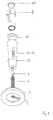
- FIG. 1 shows the basic concept of the lamp according to the invention. Is on a pedestal a threaded tube 3 or a telescopic holder for the lamp, i.e. preferably a halogen lamp 4 is arranged. This is optional but not mandatory the height position of the lamp within the lamp adjustable. Then that's it Illuminant surrounded by an outer body 12.
- the outer body contains one Slit, which in this example with sliding aperture means 13, 14 in this Representation is closed. However, these aperture means are in any gap width can be pushed open and closed.
- This outer body 12 receives the lamp body 8, which is fully inserted into the outer body 12.
- the lamp body surrounds the illuminant arranged in the interior of the outer body then directly. Also the lamp body has a slot.
- the outer wall of the lamp body 8 and the inner wall of the outer body 12 are in the sense of a sliding dimension in the Dimensions matched so that they fit snugly, but still light are movable.
- the lamp body 8 is now rotatable in the outer body.
- the Rotational position to each other then releases a resulting slot width to the outside, so that even the smallest vertical gap widths can be set. If so Aperture means 13, 14 are also pushed on, then there is also a additional adjustability of the slot length. This can be set to the extent that only one smallest spot can be set in one slot.
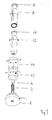
- a multi-stage base 1 a lamp is provided with a threaded tube 3, which in a central Opening 2 with internal thread is screwed in.
- the base 1 has a side Access 5 for the electrical lines 6 through the threaded tube 3 and are connected to a halogen lamp 4, the base 7 at the upper end of the Threaded tube 3 is attached.
- the threaded tube as a holder for the lamp 4 is not necessarily. It can also be a telescopic, made of sliding sleeves height-adjustable holder for the lamp, i.e. for the illuminant.
- a hollow cylindrical lamp body 8 is screwed on, the one Wall 10 and one in the wall 10 shown in the drawing Has longitudinal slot as a light opening 9.
- the top is Luminaire body 8 closed with a cap 11.
- At the top of the wall 10 of the lamp body 8 are two sleeves 13, 14 as the outer body 12 appropriate fits and in particular via recessed rubber rings 15, 16 in the arrow directions 17 continuously adjustable and attached self-adhesive. The Adjustment of these sleeves 13 and 14 gives the slit-shaped light opening 9 more or less free.
- All components are made of metal, especially light metal, with the exception such components as the halogen lamp including base, threaded tube, electrical Leads and the like that are not made of metal, in particular Allow light metal, such as the parts and components, the structure and the characterize special mode of action of lights according to the invention.
- the cap 11 can be provided with ventilation openings for heat dissipation, or be removed entirely for this purpose.
- the thread between the Luminaire body 8 and the threaded tube 3 is also a rotational movement of the Luminaire body 8 compared to the base 1 easily possible, the Light opening or the slot 9 as such can still be rotated through 360 °.
- the lamp body 8 can be coated on the inside to increase the luminous efficiency.
- the body forming the inner wall can also be the outer body be slotted.
- a shift or twist always causes one more or less clearance of the slit as a light emission opening.
- FIG 5 shows the representation of the lamp of Figure 4 again in perspective. There is the position of the individual elements in their technical context of effects shown. Otherwise, the individual elements are the same as in Figure 4 already shown.
- Figure 6 shows the lamp with a cylindrical lamp body 8 and a at least on the outside cubic outer body 12.
- the inner wall of the outer body is however also cylindrical, so that the inserted lamp body is guided in it and can be rotatably arranged.
- the aperture means 13 and 14 are as Outer cubes on the cubic outer body can now be moved so that they Cover the slit in the outer body more or less. The result is the same effect as already described in Figure 1, what the variable Adjustment of the slot length and the slot width affects.
- FIG. 7 shows a round system in which the lamp body 10, outer body 12 and the diaphragm means are cylindrical and can be pushed one above the other and / or one into the other in the manner described.
Landscapes
- Engineering & Computer Science (AREA)
- General Engineering & Computer Science (AREA)
- Non-Portable Lighting Devices Or Systems Thereof (AREA)
Abstract
Description
Die bisher bekannten Lichtquellen für die Raum- oder Objektbeleuchtung weisen den Nachteil auf, dass ihre Lichtführung starr ist. Es mangelt an Anpassungsfähigkeit für den jeweiligen Bedarfsfall.
Mehr noch. Es lassen sich mit diesem kompakten Leuchtensystem unterschiedliche Lichtaustrittsöffnungen und Spots erzeugen.
In vorteilhafter Ausgestaltung ist angegeben, dass der verstellbare Lichtspalt linear ist, so dass sich entgegen dem eingangs beschriebenen Stand der Technik eine definierte Spaltform ergibt.
Aufgrund Ihrer Vorteile ist die erfindungsgemäße Leuchte ein wichtiges Hilfsmittel für die Objektfotografie.
Wie ein Ausführungsbeispiel veranschaulicht, lässt die Erfindung nur minimales Streulicht zu.
Die erfindungsgemäße Leuchte ist ökonomisch, d.h., sie hat einen geringen Energieverbrauch (5-10 Watt).
Die erfindungsgemäße Leuchte ist platzsparend, und sie läßt sich an praktisch jedem Ort installieren.
Die Produktion einer erfindungsgemäßen Leuchte ist mit geringem Material - und Arbeitszeitaufwand möglich.
Die neue Leuchte gestattet eine sehr einfache Handhabung.
Die erfindungsgemäße Leuchte ist ein eigenständiges Gerät und erfordert keine Umbauten oder Einbauten oder dergleichen.
- Fig. 1:
- eine perspektivische Ansicht eines Ausführungsbeispiels einer erfindungsgemäßen Leuchte.
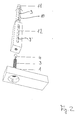
- Fig. 2:
- eine perspektivische Ansicht eines anderen Ausführungsbeispiels.
- Fig. 3:
- eine perspektivische Ansicht eines weiteren Ausführungsbeispiels.
- Fig. 4:
- Ausführungsbeispiel.
- Fig. 5:
- eine auseinandergezogene perspektivische Ansicht der Bauteile der Leuchte von Figur 4.
- Fig. 6:
- Leuchte mit kubischen Blendenmitteln aussen, sowie zylindrischem Leuchtenkörper und kubischem Aussenkörper.
- Fig. 7:
- Leuchte mit zylindrischen Blendenmitteln aussen, sowie zylindrischem Leuchtenkörper und zylindrischem Aussenkörper.
Figur 7 zeigt ein rundes System, bei welchem Leuchtenkörper 10, Aussenkörper 12 und die Blendenmittel zylindrisch sind und in der beschriebenen Weise übereinander und/oder ineinander schiebbar sind.
Claims (16)
- Leuchte, mit einem Leuchtenkörper (8), der einen von einer Wandung (10) umschlossenen Innenraum und eine Lichtquelle (4) in dem Innenraum aufweist, sowie mit mindestens einer Lichtöffnung (9) in der Wandung (10) durch die - wenn die Lichtquelle (4) eingeschaltet ist - mindestens ein Lichtstrahl von der Lichtquelle (4) nach außen fällt,
dadurch gekennzeichnet, dass mindestens ein Außenkörper (12) vorgesehen ist, der derart bewegbar an oder in der Wandung (10) des Leuchtenkörpers (8) angeordnet ist, dass Form und/oder Größe der Lichtöffnung (9) durch eine Veränderung der Position des Außenkörpers (12) an dem Leuchtenkörper (8) veränderbar sind. - Leuchte nach Anspruch 1,
dadurch gekennzeichnet, dass die Lichtöffnung (9) in der Wandung (10) so gestaltet ist, dass eine Bewegung des Außenkörpers (12) einen Lichtspalt erzeugt, der je nach Stellung von Aussenkörper (12) und Lichtöffnung (9) der Wandung (10) in seiner Spaltbreite variierbar ist. - Leuchte nach Anspruch 2,
dadurch gekennzeichnet, dass der verstellbare Lichtspalt linear ist. - Leuchte nach Anspruch 2 oder 3,
dadurch gekennzeichnet, dass in Zusammenwirken mit dem verstellbaren linearen Spalt über die Blendenmittel (13, 14) welche in etwa entlang der linearen Ausrichtung des Lichtspaltes verschiebbar sind und einen zweiten Lichtspalt in etwa orthogonal zum ersten Lichtspalt derart überlagern, dass der effektive Spalt sich sowohl in seiner Länge als auch in seiner Breite verstellen lässt. - Leuchte nach einem der vorhergehenden Ansprüche
dadurch gekennzeichnet, dass in den Blendenmitteln (13, 14) Zusätzlich feste Lichtaustrittsöffnungen vorgesehen sind, mit denen punktförmige Lichtaustrittsflächen erzeugt werden können. - Leuchte nach Anspruch 5,
dadurch gekennzeichnet, dass die punktförmigen Lichtaustrittsöffnungen mit optischen Linsenkörpern versehen sind. - Leuchte nach einem der vorhergehenden Ansprüche,
dadurch gekennzeichnet, dass hinter den Blendenmitteln (13, 14) optische Linsenkörper angeordnet sind. - Leuchte nach einem der vorhergehenden Ansprüche,
dadurch gekennzeichnet, dass innerhalb des Aussenkörpers (12) optische Linsenkörper angeordnet sind. - Leuchte nach einem der vorhergehenden Ansprüche,
dadurch gekennzeichnet, dass innerhalb der Wandung (10) optische Linsenkörper angeordnet sind. - Leuchte nach einem der vorhergehenden Ansprüche,
dadurch gekennzeichnet, dass innerhalb der Leuchte in Bezug auf die Lichtaustrittsöffnung bzw den Lichtaustrittsspalt ein Reflektor hinter dem Leuchtmittel (4) angeordnet ist, derart, dass das Leuchtmittel stets zwischen Reflektor und Lichtaustrittsöffnung liegt. - Leuchte nach Anspruch 10,
dadurch gekennzeichnet, dass der Reflektor an die Bewegung des Lichtspaltes bzw bewegungsmäßig an den Leuchtenkörper (8) oder den Aussenkörper (12) gekoppelt ist, derart, dass auch bei Drehung des Leuchtenkörpers (8) und/oder des Aussenkörpers (12) der Reflektor so mitgedreht wird, dass das Leuchtmittel stets zwischen Reflektor und Lichtspalt liegt. - Leuchte nach einem der vorhergehenden Ansprüche,
dadurch gekennzeichnet, dass die Blendenmittel (13, 14) innerhalb des Aussenkörpers (12) verschieblich angeordnet sind. - Leuchte nach einem der vorhergehenden Ansprüche,
dadurch gekennzeichnet, dass die Blendenmittel (13, 14) aussen am Aussenkörper (12) verschieblich angeordnet sind. - Leuchte nach einem der vorhergehenden Ansprüche,
dadurch gekennzeichnet, dass der Leuchtenkörper (8) ein Hohlzylinder und der oder die Außenkörper (13) jeweils einen Ring oder eine Hülse (13, 14) bilden, die die Wandung (10) des Leuchtenkörpers (8) umschließt und die Lichtöffnung (9) je nach ihrer Position mehr oder weniger verdeckt, so dass die Form und Größe des nach außen fallenden Lichtstrahls durch die jeweilige Position des oder der Außenkörper (12) bestimmt wird. - Leuchte nach einem der vorhergehenden Ansprüche,
dadurch gekennzeichnet, dass der die Wandung (10) bildende Körper einen ersten Längsschlitz (9) aufweist, der mit mindestens einem Längsschlitz (9') des Aussenkörpers durch Drehen oder Schieben mehr oder weniger zur Deckung gebracht werden kann. - Leuchte nach einem der vorhergehenden Ansprüche,
dadurch gekennzeichnet, dass der Leuchtenkörper (8), der Aussenkörper (12) und die Blendenmittel (13, 14) in Ihren Aussen- und/oder Innenabmessungen so aufeinander abgestimmt sind, das diese Teile nach Art eines funktionalen Gestaltungsbaukastens untereinander austauschbar sind, und die Teile zumindest mit einer Gleitpassung aufeinander verschiebbar/drehbar sind.
Applications Claiming Priority (2)
| Application Number | Priority Date | Filing Date | Title |
|---|---|---|---|
| DE2002159447 DE10259447B4 (de) | 2002-12-19 | 2002-12-19 | Leuchte mit veränderbarer Lichtstärkenverteilung |
| DE10259447 | 2002-12-19 |
Publications (2)
| Publication Number | Publication Date |
|---|---|
| EP1431655A2 true EP1431655A2 (de) | 2004-06-23 |
| EP1431655A3 EP1431655A3 (de) | 2005-12-07 |
Family
ID=32336465
Family Applications (1)
| Application Number | Title | Priority Date | Filing Date |
|---|---|---|---|
| EP03029042A Withdrawn EP1431655A3 (de) | 2002-12-19 | 2003-12-16 | Leuchte |
Country Status (2)
| Country | Link |
|---|---|
| EP (1) | EP1431655A3 (de) |
| DE (1) | DE10259447B4 (de) |
Cited By (3)
| Publication number | Priority date | Publication date | Assignee | Title |
|---|---|---|---|---|
| DE102005006758A1 (de) * | 2005-02-15 | 2006-08-24 | Norbert Wagner | Beleuchtungseinrichtung mit einer Lichtquelle und einem Leuchtengehäuse |
| DE102005046871A1 (de) * | 2005-09-30 | 2007-04-12 | Norbert Wagner | Beleuchtungseinrichtung mit einem mit Schlitz versehenen Gehäuse |
| GB2479021A (en) * | 2010-03-26 | 2011-09-28 | Gary Banks | Tubular lamp with movable reflectors giving side lighting or up lighting |
Citations (3)
| Publication number | Priority date | Publication date | Assignee | Title |
|---|---|---|---|---|
| US2374161A (en) | 1943-11-10 | 1945-04-24 | Kemper Thomas Company | Lamp shading device |
| DE858724C (de) | 1943-08-31 | 1952-12-08 | Heinz Dipl-Ing Peter | Lampe mit verstellbarer Lichtaustrittsoeffnung |
| DE29510758U1 (de) | 1995-07-03 | 1995-10-19 | Goeddertz, Stefan, 92637 Weiden | Lampe/mechanischer Dimmer |
Family Cites Families (4)
| Publication number | Priority date | Publication date | Assignee | Title |
|---|---|---|---|---|
| DE858727C (de) * | 1951-03-31 | 1952-12-08 | Josef Dipl-Ing Erz | Gluehlampe zu Beleuchtungs- und Signalzwecken fuer Kraftfahrzeuge |
| US4074124A (en) * | 1976-09-22 | 1978-02-14 | Maute Charles J | Illumination apparatus for simulating night, dawn and morning, mid-day and afternoon and dusk natural light conditions |
| DE3826161A1 (de) * | 1988-08-01 | 1990-02-08 | Stiers Unterhaltungselektronik | Lichtfaechergeraet |
| US5233198A (en) * | 1992-01-10 | 1993-08-03 | Changaris David G | Mechanical apparatus to ensure that only pulses of radiation are radiated in any specific direction |
-
2002
- 2002-12-19 DE DE2002159447 patent/DE10259447B4/de not_active Expired - Fee Related
-
2003
- 2003-12-16 EP EP03029042A patent/EP1431655A3/de not_active Withdrawn
Patent Citations (3)
| Publication number | Priority date | Publication date | Assignee | Title |
|---|---|---|---|---|
| DE858724C (de) | 1943-08-31 | 1952-12-08 | Heinz Dipl-Ing Peter | Lampe mit verstellbarer Lichtaustrittsoeffnung |
| US2374161A (en) | 1943-11-10 | 1945-04-24 | Kemper Thomas Company | Lamp shading device |
| DE29510758U1 (de) | 1995-07-03 | 1995-10-19 | Goeddertz, Stefan, 92637 Weiden | Lampe/mechanischer Dimmer |
Cited By (4)
| Publication number | Priority date | Publication date | Assignee | Title |
|---|---|---|---|---|
| DE102005006758A1 (de) * | 2005-02-15 | 2006-08-24 | Norbert Wagner | Beleuchtungseinrichtung mit einer Lichtquelle und einem Leuchtengehäuse |
| DE102005046871A1 (de) * | 2005-09-30 | 2007-04-12 | Norbert Wagner | Beleuchtungseinrichtung mit einem mit Schlitz versehenen Gehäuse |
| GB2479021A (en) * | 2010-03-26 | 2011-09-28 | Gary Banks | Tubular lamp with movable reflectors giving side lighting or up lighting |
| GB2479021B (en) * | 2010-03-26 | 2012-10-31 | Gary Banks | Lamp |
Also Published As
| Publication number | Publication date |
|---|---|
| EP1431655A3 (de) | 2005-12-07 |
| DE10259447A1 (de) | 2004-07-08 |
| DE10259447B4 (de) | 2005-02-03 |
Similar Documents
| Publication | Publication Date | Title |
|---|---|---|
| DE69802532T2 (de) | Beleuchtungseinrichtung | |
| DE2305666B2 (de) | Operationsleuchte | |
| DE102006019194A1 (de) | Mehrseitige Beleuchtungsanordnung mit Entblendung | |
| EP1431655A2 (de) | Leuchte | |
| DE10161468A1 (de) | Leuchte | |
| EP1626226B1 (de) | Leuchte mit rotationssymmetrischem Reflektor | |
| DE202004001178U1 (de) | Stehlampe, insbesondere mit verschiebbaren Lampenschirmen zur Installierung einer beliebigen Anzahl von Glühbirnen | |
| DE4332352C2 (de) | Leuchte mit einer Verstellvorrichtung für mindestens zwei Reflektoren | |
| DE102008022357B4 (de) | Leuchte, insbesondere Decken- oder Wandleuchte | |
| DE102004051661B3 (de) | Leuchte und Lichtquelleneinheit zur Ausleuchtung einer Gebäudefläche oder einer Gebäudeteilfläche | |
| DE1275493B (de) | Strassenleuchte | |
| DE2223728C3 (de) | Strahlerleuchte | |
| WO2006087172A1 (de) | Beleuchtungseinrichtung mit einer lichtquelle und einem leuchtengehäuse | |
| DE4413111A1 (de) | Asymmetrische Leuchte | |
| DE102004058750A1 (de) | Einseitig gesockelte Hochdruckentladungslampe | |
| EP0347700B1 (de) | Leuchte | |
| DE19527585C2 (de) | Leuchte | |
| DE102011055328B4 (de) | Blende mit mehreren schwenkbeweglich angeordneten Lamellen sowie eine mit einer solchen Blende ausgestattete Leuchte | |
| DE2833188A1 (de) | Beleuchtungskoerper | |
| DE69106016T2 (de) | Einen fächerförmigen Lichtstrahl erzeugende Beleuchtungsvorrichtung. | |
| DE9103102U1 (de) | Lampenschirm für eine Straßen- oder Platzleuchte | |
| DE102005046871A1 (de) | Beleuchtungseinrichtung mit einem mit Schlitz versehenen Gehäuse | |
| DE19509480A1 (de) | Leuchte | |
| DE19821762B4 (de) | Standleuchte mit variabler Abstrahlcharakteristik | |
| DE29512156U1 (de) | Leuchte |
Legal Events
| Date | Code | Title | Description |
|---|---|---|---|
| PUAI | Public reference made under article 153(3) epc to a published international application that has entered the european phase |
Free format text: ORIGINAL CODE: 0009012 |
|
| AK | Designated contracting states |
Kind code of ref document: A2 Designated state(s): AT BE BG CH CY CZ DE DK EE ES FI FR GB GR HU IE IT LI LU MC NL PT RO SE SI SK TR |
|
| AX | Request for extension of the european patent |
Extension state: AL LT LV MK |
|
| PUAL | Search report despatched |
Free format text: ORIGINAL CODE: 0009013 |
|
| AK | Designated contracting states |
Kind code of ref document: A3 Designated state(s): AT BE BG CH CY CZ DE DK EE ES FI FR GB GR HU IE IT LI LU MC NL PT RO SE SI SK TR |
|
| AX | Request for extension of the european patent |
Extension state: AL LT LV MK |
|
| 17P | Request for examination filed |
Effective date: 20060427 |
|
| AKX | Designation fees paid |
Designated state(s): AT BE BG CH CY CZ DE DK EE ES FI FR GB GR HU IE IT LI LU MC NL PT RO SE SI SK TR |
|
| 17Q | First examination report despatched |
Effective date: 20070327 |
|
| GRAP | Despatch of communication of intention to grant a patent |
Free format text: ORIGINAL CODE: EPIDOSNIGR1 |
|
| STAA | Information on the status of an ep patent application or granted ep patent |
Free format text: STATUS: THE APPLICATION IS DEEMED TO BE WITHDRAWN |
|
| 18D | Application deemed to be withdrawn |
Effective date: 20080701 |