EP1431659A1 - Stecksystem für Rohrverbindungen mit nichtlinearen kontinuierlichen Abschnitten - Google Patents
Stecksystem für Rohrverbindungen mit nichtlinearen kontinuierlichen Abschnitten Download PDFInfo
- Publication number
- EP1431659A1 EP1431659A1 EP03027803A EP03027803A EP1431659A1 EP 1431659 A1 EP1431659 A1 EP 1431659A1 EP 03027803 A EP03027803 A EP 03027803A EP 03027803 A EP03027803 A EP 03027803A EP 1431659 A1 EP1431659 A1 EP 1431659A1
- Authority
- EP
- European Patent Office
- Prior art keywords
- section
- pipe
- plug
- linear
- linear continuous
- Prior art date
- Legal status (The legal status is an assumption and is not a legal conclusion. Google has not performed a legal analysis and makes no representation as to the accuracy of the status listed.)
- Granted
Links
- 229910000831 Steel Inorganic materials 0.000 claims description 2
- 229910001220 stainless steel Inorganic materials 0.000 claims description 2
- 239000010935 stainless steel Substances 0.000 claims description 2
- 239000010959 steel Substances 0.000 claims description 2
- 238000007789 sealing Methods 0.000 description 11
- 239000007789 gas Substances 0.000 description 8
- 230000004858 capillary barrier Effects 0.000 description 5
- 238000005516 engineering process Methods 0.000 description 5
- 239000000919 ceramic Substances 0.000 description 4
- 238000002485 combustion reaction Methods 0.000 description 4
- 238000010276 construction Methods 0.000 description 4
- 238000003780 insertion Methods 0.000 description 4
- 230000037431 insertion Effects 0.000 description 4
- 239000012774 insulation material Substances 0.000 description 4
- 238000009418 renovation Methods 0.000 description 4
- 238000004378 air conditioning Methods 0.000 description 3
- 239000011324 bead Substances 0.000 description 3
- 230000000694 effects Effects 0.000 description 3
- 238000010438 heat treatment Methods 0.000 description 3
- 239000011810 insulating material Substances 0.000 description 3
- 238000004519 manufacturing process Methods 0.000 description 3
- 239000000463 material Substances 0.000 description 3
- 239000002557 mineral fiber Substances 0.000 description 3
- XLYOFNOQVPJJNP-UHFFFAOYSA-N water Substances O XLYOFNOQVPJJNP-UHFFFAOYSA-N 0.000 description 3
- QAOWNCQODCNURD-UHFFFAOYSA-N Sulfuric acid Chemical compound OS(O)(=O)=O QAOWNCQODCNURD-UHFFFAOYSA-N 0.000 description 2
- 230000032683 aging Effects 0.000 description 2
- 239000004744 fabric Substances 0.000 description 2
- 238000009434 installation Methods 0.000 description 2
- 239000004033 plastic Substances 0.000 description 2
- 238000003825 pressing Methods 0.000 description 2
- 230000008439 repair process Effects 0.000 description 2
- 239000003566 sealing material Substances 0.000 description 2
- 230000006641 stabilisation Effects 0.000 description 2
- 238000011105 stabilization Methods 0.000 description 2
- 238000009423 ventilation Methods 0.000 description 2
- YCKRFDGAMUMZLT-UHFFFAOYSA-N Fluorine atom Chemical compound [F] YCKRFDGAMUMZLT-UHFFFAOYSA-N 0.000 description 1
- GRYLNZFGIOXLOG-UHFFFAOYSA-N Nitric acid Chemical compound O[N+]([O-])=O GRYLNZFGIOXLOG-UHFFFAOYSA-N 0.000 description 1
- IOVCWXUNBOPUCH-UHFFFAOYSA-N Nitrous acid Chemical compound ON=O IOVCWXUNBOPUCH-UHFFFAOYSA-N 0.000 description 1
- LSNNMFCWUKXFEE-UHFFFAOYSA-N Sulfurous acid Chemical compound OS(O)=O LSNNMFCWUKXFEE-UHFFFAOYSA-N 0.000 description 1
- 238000004364 calculation method Methods 0.000 description 1
- 239000000470 constituent Substances 0.000 description 1
- 238000005520 cutting process Methods 0.000 description 1
- 229920001971 elastomer Polymers 0.000 description 1
- 239000011737 fluorine Substances 0.000 description 1
- 229910052731 fluorine Inorganic materials 0.000 description 1
- 230000005484 gravity Effects 0.000 description 1
- 230000020169 heat generation Effects 0.000 description 1
- 238000009413 insulation Methods 0.000 description 1
- 239000007769 metal material Substances 0.000 description 1
- 229910017604 nitric acid Inorganic materials 0.000 description 1
- GQPLMRYTRLFLPF-UHFFFAOYSA-N nitrous oxide Inorganic materials [O-][N+]#N GQPLMRYTRLFLPF-UHFFFAOYSA-N 0.000 description 1
- 229920001296 polysiloxane Polymers 0.000 description 1
- 238000010248 power generation Methods 0.000 description 1
- 239000005060 rubber Substances 0.000 description 1
- 125000006850 spacer group Chemical group 0.000 description 1
- 230000000087 stabilizing effect Effects 0.000 description 1
- 230000003319 supportive effect Effects 0.000 description 1
Images




Classifications
-
- F—MECHANICAL ENGINEERING; LIGHTING; HEATING; WEAPONS; BLASTING
- F23—COMBUSTION APPARATUS; COMBUSTION PROCESSES
- F23J—REMOVAL OR TREATMENT OF COMBUSTION PRODUCTS OR COMBUSTION RESIDUES; FLUES
- F23J13/00—Fittings for chimneys or flues
- F23J13/04—Joints; Connections
-
- F—MECHANICAL ENGINEERING; LIGHTING; HEATING; WEAPONS; BLASTING
- F16—ENGINEERING ELEMENTS AND UNITS; GENERAL MEASURES FOR PRODUCING AND MAINTAINING EFFECTIVE FUNCTIONING OF MACHINES OR INSTALLATIONS; THERMAL INSULATION IN GENERAL
- F16L—PIPES; JOINTS OR FITTINGS FOR PIPES; SUPPORTS FOR PIPES, CABLES OR PROTECTIVE TUBING; MEANS FOR THERMAL INSULATION IN GENERAL
- F16L39/00—Joints or fittings for double-walled or multi-channel pipes or pipe assemblies
- F16L39/005—Joints or fittings for double-walled or multi-channel pipes or pipe assemblies for concentric pipes
-
- F—MECHANICAL ENGINEERING; LIGHTING; HEATING; WEAPONS; BLASTING
- F16—ENGINEERING ELEMENTS AND UNITS; GENERAL MEASURES FOR PRODUCING AND MAINTAINING EFFECTIVE FUNCTIONING OF MACHINES OR INSTALLATIONS; THERMAL INSULATION IN GENERAL
- F16L—PIPES; JOINTS OR FITTINGS FOR PIPES; SUPPORTS FOR PIPES, CABLES OR PROTECTIVE TUBING; MEANS FOR THERMAL INSULATION IN GENERAL
- F16L59/00—Thermal insulation in general
- F16L59/14—Arrangements for the insulation of pipes or pipe systems
- F16L59/16—Arrangements specially adapted to local requirements at flanges, junctions, valves or the like
- F16L59/18—Arrangements specially adapted to local requirements at flanges, junctions, valves or the like adapted for joints
- F16L59/182—Joints with sleeve or socket
-
- F—MECHANICAL ENGINEERING; LIGHTING; HEATING; WEAPONS; BLASTING
- F24—HEATING; RANGES; VENTILATING
- F24F—AIR-CONDITIONING; AIR-HUMIDIFICATION; VENTILATION; USE OF AIR CURRENTS FOR SCREENING
- F24F13/00—Details common to, or for air-conditioning, air-humidification, ventilation or use of air currents for screening
- F24F13/02—Ducting arrangements
-
- F—MECHANICAL ENGINEERING; LIGHTING; HEATING; WEAPONS; BLASTING
- F23—COMBUSTION APPARATUS; COMBUSTION PROCESSES
- F23J—REMOVAL OR TREATMENT OF COMBUSTION PRODUCTS OR COMBUSTION RESIDUES; FLUES
- F23J2213/00—Chimneys or flues
- F23J2213/20—Joints; Connections
- F23J2213/202—Joints; Connections between duct or stack sections
Definitions
- the invention relates to a connector system for pipe connections with non-linear continuous sections for use in industrial, domestic and in automotive field.
- Plug-in system for pipe connections for supply and / or Discharge of gases in use are particularly in the area of exhaust systems and Ventilation and air conditioning technology.
- Plug-in systems for pipe connections in the Automotive engineering and also in the stationary area such as in combined heat and power plants, where Exhaust gases derived from an engine are in use.
- Typical combustion plants are heat generation plants and engines, such as those used for Water heating, for heating purposes, for power generation, for drive purposes, as Combined heat and power plants or the like in domestic, industrial and automotive Area.
- Plug systems are suitable for new buildings as well as for the renovation and repair of Old plants.
- Heating systems can also be used in combination, e.g. to simultaneous guidance of two gases, for example via the outer tube, one Heating system can be supplied with combustion air, while the inner tube the exhaust / the exhaust air discharges.
- systems can also be double-walled and pre-assembled insulating material may be provided.
- Typical insulation materials are e.g. Mineral fibers, ceramic fabrics, ceramic tiles, or the like.
- European patent EP 0 780 635 B1 relates to a chimney pipe for the Chimney renovation from several pipe sections, each a conically expanded End and a tapered end with the same cone angles and through Inserting the tapered end into the expanded end can be connected to each other.
- conical sections have the property sensitive to damage such as e.g. Transport damage, to react because the linear surface in case of damage no longer allows the desired form fit.
- sealing materials e.g. Sealing rings, sealing lips or sealing pastes are used
- additional clamping elements e.g. Pipe clamps can be used to meet the required To achieve tightness.
- the exhaust gases also contain aggressive constituents, such as SO 2 , SO 3 , NO, NO 2 , NO 3 . If these dissolve in water, which is also part of the combustion air in the form of water vapor, a highly aggressive condensate forms.
- sealing materials such as e.g. Rubbers on Silicone base or fluorine base cannot be used or can only be used with restrictions, as these due to sulfurous components, e.g. sulfurous acid or sulfuric acid, and / or nitrous components such as e.g. nitrous acid or nitric acid, in the exhaust gases or the condensate of the combustion air and even by concentration can be destroyed.
- sulfurous components e.g. sulfurous acid or sulfuric acid
- nitrous components such as e.g. nitrous acid or nitric acid
- the European patent application EP 1 188 979 A2 relates to a pipe connection which in addition to the already known connecting device a pretensioning device in Has the shape of spring clips, in such a way that in their operative position a Axial direction holding force is exerted on the pipe sections.
- Pipe clamps or similar elements act radially on the pipe connection. A Axial securing of the connection can only achieve this insufficiently.
- the invention has for its object to provide a connector system for pipe connections To provide a reliable seal. It is still the job of Invention to provide a connector system for pipe connections that is simple is mountable. It is also an object of the invention to provide a plug-in system for To provide pipe connections that are both horizontal and vertical Use seals. It is a further object of the invention to provide a plug-in system for Pipe connections that provide further leak tightness on use supportive means waived or minimized. It is also an object of the invention to provide a connector system for pipe connections that is also not collinear Pipe connections with reliable tightness and better self-locking provides.
- a plug-in system for pipe connections with one end of a single-walled tube as a plug-in part and one end of a single-walled tube as Sleeve part is formed, and both the male part and the sleeve part one have non-linear continuous section.
- the plug-in part is the end piece of a tube and has an enlarged end.
- the configuration of the expansion to the expanded end can be carried out in a suitable manner respectively.
- the expansion can be linear in sections, but is also any other design possible, for example a non-linear, continuous course.
- the expansion is followed by a non-linear continuous section.
- the design of the non-linear continuous section can be different Have shapes.
- the nonlinear continuous section preferably has a constant curvature, however, it would also be possible to have a continuously changing, e.g. one monotonous to provide changing curvature.
- the sleeve part is the end piece of a pipe and has an enlarged end.
- the configuration of the expansion to the expanded end can be carried out in a suitable manner respectively.
- the expansion can be linear in sections, but is also any other design possible, for example a non-linear continuous course.
- the expansion is followed by a non-linear continuous section.
- the design of the non-linear continuous section can in turn be done have different shapes.
- This non-linear continuous section preferably also has a constant one Curvature, but it would also be possible to have a continuously changing, e.g. a to provide monotonically changing curvature.
- the sleeve part can have a receptacle at the upper end.
- the recording can be configured in a suitable manner Sections can be linear in sections, but any other design is also possible, for example a non-linear, continuous course.
- inventive Pipe system continues to offer the possibility even pipes that are not in their axes are collinear to connect with the help of a joint-like connection at the same time Fulfillment of the tightness requirements.
- the two pipe ends form fit together and offer the required tightness, even if the axes of the pipes are not collinear.
- clamping elements there are no further clamping elements to maintain tightness required.
- clamping elements can be used in environments where there is a risk of vibration supporting stabilization of the connection can be used.
- sealing elements can also on the use of other, partly strong attack and / or aging processes underlying sealing elements, such as Sealing lips, sealing rings or sealing pastes different bases are waived.
- the non-linear, continuous shape of the sections distributes itself Effects of force, e.g. through transport-typical impacts, better on the overall structure. There this varies, such actions are mechanically better absorbed and it there is no essential, permanent plastic jeopardizing the tightness Deformation.
- the plug-in system according to the invention offers the possibility of self-locking the pipes to be easily detachable in both horizontal and vertical alignment. This can by appropriate choice of the non-linear continuous section, e.g. B. by choice of a corresponding radius.
- the plug-in system according to the invention can have a bead, which as Capillary barrier and / or serves as a moisture collector and an outlet of condensate prevented.
- the receptacle of the sleeve part can be designed so that it as Stop line for attaching and aligning a clamping band is used if the Attachment of such a tape should be necessary.
- the socket part can be designed so that it tolerances, e.g. manufacturing-related tolerances and / or damage, e.g. Transport damage, des Insert part takes.
- the tube end of the plug-in part can have a cylindrical section which to further stiffen the pipe and in particular the non-linear one continuous section leads.
- tubes are made of a flat material by stamping or cutting can be worked out in a raw form and in further steps Pipe blanks are bent and welded. Further steps include forming the pipe ends to the aforementioned non-linear continuous sections.
- the above-mentioned systems can be both single and double-walled and in a double-walled version either with insulating material and / or the Possibility to carry another gas.
- inner tubes and outer tubes can be used have different or the same curvature.
- stabilization between the pipes can also take place be inserted, either by inserting an insulation material, or by Spacers.
- Typical insulation materials are e.g. Mineral fibers, ceramic fabrics, ceramic fleece, or the like. As a preferred material for insulation Mineral fiber-based insulation material preferred.
- the pipe system according to the invention is for all nominal sizes, for the exhaust or Ventilation systems according to the technical design / calculation are applicable.
- Fig. 1a is a male part and in Fig. 1b a corresponding sleeve part Embodiment A shown.
- the plug-in part is the end piece of a pipe 1 with a nominal cross section DN and has an end 2.3 extended over the nominal cross-section DN.
- the design of the Widening 2 from the nominal diameter DN to the section can be done in a suitable manner and is only shown as an example as a linear expansion in sections. To the Expansion 2 closes an area with a non-linear, continuous section 3 on.
- section 3 has a constant curvature, i.e. the section forms a section of a circle.
- the section has a fixed outside radius R1 and Length H2.
- the spatial body can be rotated by rotating this section of the circle describe the tube axis as a spherical segment.
- the sleeve part is the end piece of a pipe 8 with the nominal cross section DN, as in Fig. 1b, and has an end 7, 6, 5 which is enlarged beyond the nominal cross section DN.
- the Design of the widening 7 from the nominal diameter DN on the section can in is suitably done only as an example as a linear expansion in sections shown.
- the widening 7 could also have a bead as a capillary barrier.
- To the Widening 7 closes an area with a non-linear, continuous section 6 on.
- section 6 has a constant curvature, i.e. the section forms a section of a circle.
- the section has a fixed inner radius R1 and Length H1.
- the spatial body can be rotated by rotating this section of the circle describe the tube axis as a spherical segment.
- the sleeve part can have a receptacle 5 at the upper end.
- the Design of the receptacle 5 can be done in a suitable manner is only exemplary as shown linearly in sections.
- the receptacle is 5 of the socket part so that it acts as a stop line for the attachment and Alignment of a clamping band is used if the attachment of such a band should be required.
- the execution of the receptacle 5 allows the socket part be designed so that they tolerances, e.g. manufacturing tolerances, and / or Damage, e.g. Transport damage, the insertion part picks up when inserted.
- Fig. 2a is a male part and in Fig. 2b a corresponding sleeve part Embodiment B shown.
- the plug-in part is the end piece of a tube 11 with a nominal cross section DN and has an end 12, 13, 14 widened over the nominal cross section DN.
- the design the widening 12 from the nominal diameter DN to the section can be suitably is shown only by way of example as a linear expansion in sections. To the Widening 12 closes an area with a non-linear, continuous Section 13.
- section 13 has a constant curvature, i.e. the section forms a section of a circle.
- the section has a fixed outside radius R2 and the Length H6.
- the spatial body can be rotated by rotating this section of the circle describe the tube axis as a spherical segment.
- the insertion part can have a cylindrical section 14 at the lower end exhibit.
- the design of section 14 is a cylindrical section with a Length resulting from the difference between H4 and H6.
- the cylindrical section 14 has the nominal diameter DN.
- the cylindrical section 14 can be in length (H4-H6) be shorter than section 13. The length is only dimensioned exemplary, other suitable length dimensions are also possible.
- the present embodiment of the cylindrical section 14 serves a further one Stiffening of the pipe around the pipe end and especially the nonlinear, continuous section 13 further from damage and deformation, e.g. to protect by transport damage.
- the sleeve part as shown in Fig. 2b, is the end piece of a tube 18 with the Nominal cross section DN and has an end 17, 16, 15 which is expanded beyond the nominal cross section DN on.
- the configuration of the widening 17 from the nominal diameter DN to the enlarged part can be done in a suitable manner is only exemplary as linear in sections Widening shown. Furthermore, the widening has a length that results from the Difference of H3 and H5 results.
- the widening 17 has a diameter that is larger than the nominal diameter DN. It preferably has a diameter that turns out to be suitable for section 14.
- the widening 17 can be in length (H3-H5) be shorter than section 16.
- the length dimensioning is only an example, other suitable length dimensions are also possible.
- the Widening 17 also have a bead as a capillary barrier.
- section 16 has a constant curvature, i.e. the section forms a section of a circle.
- the section has a fixed inner radius R1 and has the Length H5.
- the spatial body can be rotated by rotating this section of the circle describe the tube axis as a spherical segment.
- the sleeve part has a receptacle 15 at the upper end.
- the design the recording 15 can be done in a suitable manner is only exemplary as linear recording shown in sections.
- the Recording 15 of the socket part designed so that it as a stop line for attachment and alignment of a clamping band is used if the attachment of such a band should be required.
- the execution of the receptacle 15 of the socket part allows be designed so that they tolerances, e.g. manufacturing tolerances, and / or Damage, e.g. Transport damage, the insertion part picks up when inserted.
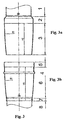
- Fig. 3a is a male part and in Fig. 3b a corresponding sleeve part Embodiment C shown, which differs from embodiment A only by this differs in that a capillary barrier 4 is provided in section 6 of the sleeve part.
- Fig. 4 shows an embodiment D of the invention, which is a double-walled connector system concerns.
- the connection of the Plug systems would generally be realized by means of a clamping band, not shown.
- FIG. 5 shows a further embodiment E of a double-walled plug-in system.
- the pipes of the male and female parts are through one marked self-locking design.
- the invention thus provides a pipe system with a positive metallic seal available, as sections 3 and 6 or 13 and 16 when merging through the
- the choice of identical curves lies in a form-fitting manner.
- sealing elements such as Sealing lips, sealing rings or sealing pastes different bases are waived.
- the non-linear continuous shape of the sections 3, 13, 6, 16 distributes itself Effects of force, e.g. through transport-typical impacts, better on the overall structure.
Landscapes
- Engineering & Computer Science (AREA)
- General Engineering & Computer Science (AREA)
- Mechanical Engineering (AREA)
- Chemical & Material Sciences (AREA)
- Combustion & Propulsion (AREA)
- Quick-Acting Or Multi-Walled Pipe Joints (AREA)
- Rigid Pipes And Flexible Pipes (AREA)
- Branch Pipes, Bends, And The Like (AREA)
- Pipe Accessories (AREA)
- Electric Cable Installation (AREA)
Abstract
Description
- Fig. 1a ein Einsteckteil einer Ausführungsform A der Erfindung,
- Fig. 1b ein Muffenteil einer Ausführungsform A der Erfindung,
- Fig. 2a ein Einsteckteil einer Ausführungsform B der Erfindung,
- Fig. 2b ein Muffenteil einer Ausführungsform B der Erfindung,
- Fig. 3a ein Einsteckteil einer Ausführungsform C der Erfindung,
- Fig. 3b ein Muffenteil einer Ausführungsform C der Erfindung,
- Fig. 4 ein Einsteck- und Muffenteil einer Ausführungsform D der Erfindung,
- Fig. 4 ein Einsteck- und Muffenteil einer Ausführungsform E der Erfindung.
- 1.
- Rohr, Einsteckteil
- 2.
- Aufweitung, Einsteckteil
- 3.
- nichtlinearer kontinuierlicher Abschnitt, Einsteckteil
- 4.
- Kapillarsperre
- 5.
- Aufnahme, Muffenteil
- 6.
- nichtlinearer kontinuierlicher Abschnitt; Muffenteil
- 7.
- Aufweitung, Muffenteil
- 8.
- Rohr, Muffenteil
- 9. 10. 11.
- Rohr, Einsteckteil
- 12.
- Aufweitung, Einsteckteil
- 13.
- nichtlinearer kontinuierlicher Abschnitt, Einsteckteil
- 14.
- zylindrischer Abschnitt, Muffenteil
- 15.
- Aufnahme, Muffenteil
- 16.
- nichtlinearer kontinuierlicher Abschnitt; Muffenteil
- 17.
- Aufweitung, Muffenteil
- 18.
- Rohr, Muffenteil
Claims (7)
- Stecksystem für einwandige Rohrverbindungen, wobei ein Ende eines einwandigen Rohrs als Einsteckteil und ein Ende eines anderen einwandigen Rohrs als Muffenteil ausgebildet ist, dadurch gekennzeichnet, dass sowohl das Einsteckteil als auch das Muffenteil einen nichtlinearen kontinuierlichen Abschnitt aufweisen.
- Stecksystem für doppelwandige Rohrverbindungen, wobei ein Ende eines doppelwandigen Rohrs als Einsteckteil und ein Ende eines anderen doppelwandigen Rohrs als Muffenteil ausgebildet ist, dadurch gekennzeichnet, dass sowohl das Einsteckteil als auch das Muffenteil einen nichtlinearen kontinuierlichen Abschnitt aufweisen.
- Stecksystem für doppelwandige Rohrverbindungen gemäß Anspruch 2, dadurch gekennzeichnet, dass der nichtlinearen kontinuierlichen Abschnitt der Innenrohre und Außenrohre gleiche Krümmung aufweist.
- Stecksystem für doppelwandige Rohrverbindungen gemäß Anspruch 2, dadurch gekennzeichnet, dass der nichtlinearen kontinuierlichen Abschnitt der Innenrohre und Außenrohre ungleiche Krümmungen aufweisen.
- Stecksystem für Rohrverbindungen gemäß einem der vorhergehenden Ansprüche 1 bis 4, dadurch gekennzeichnet, dass der nichtlinear kontinuierliche Abschnitt eine konstante Krümmung aufweist.
- Stecksystem für Rohrverbindungen gemäß einem der vorhergehenden Ansprüche 1 bis 4, dadurch gekennzeichnet, dass der nichtlinear kontinuierliche Abschnitt eine sich monoton ändernde Krümmung aufweist.
- Stecksystem für Rohrverbindungen gemäß einem der vorhergehenden Ansprüche, dadurch gekennzeichnet, dass die Rohre aus Stahl, vorzugsweise Edelstahl sind.
Applications Claiming Priority (2)
| Application Number | Priority Date | Filing Date | Title |
|---|---|---|---|
| DE10260563 | 2002-12-21 | ||
| DE10260563 | 2002-12-21 |
Publications (2)
| Publication Number | Publication Date |
|---|---|
| EP1431659A1 true EP1431659A1 (de) | 2004-06-23 |
| EP1431659B1 EP1431659B1 (de) | 2007-04-04 |
Family
ID=32336583
Family Applications (1)
| Application Number | Title | Priority Date | Filing Date |
|---|---|---|---|
| EP03027803A Expired - Lifetime EP1431659B1 (de) | 2002-12-21 | 2003-12-03 | Stecksystem für Rohrverbindungen mit nichtlinearen kontinuierlichen Abschnitten |
Country Status (3)
| Country | Link |
|---|---|
| EP (1) | EP1431659B1 (de) |
| AT (1) | ATE358800T1 (de) |
| DE (1) | DE50306957D1 (de) |
Cited By (1)
| Publication number | Priority date | Publication date | Assignee | Title |
|---|---|---|---|---|
| FR2885200A1 (fr) * | 2005-04-28 | 2006-11-03 | Fldh Soc Par Actions Simplifie | Conduit de fumee ou analogue |
Families Citing this family (1)
| Publication number | Priority date | Publication date | Assignee | Title |
|---|---|---|---|---|
| EP2871416A1 (de) | 2013-11-06 | 2015-05-13 | eka edelstahlkamine gmbh | Adapterrohr für Rohrelement mit variabler Länge |
Citations (6)
| Publication number | Priority date | Publication date | Assignee | Title |
|---|---|---|---|---|
| DE810906C (de) * | 1949-09-17 | 1951-08-13 | Roesle Geb | Kugelgelenkkupplung fuer Blechrohre |
| EP0286488B1 (de) * | 1987-04-10 | 1990-12-12 | Daniel Urion | Luftdichtes Rauchleitungselement mit doppelten und wärmeisolierten Wänden |
| DE9101262U1 (de) * | 1990-02-02 | 1991-04-25 | Joh. Vaillant Gmbh U. Co, 5630 Remscheid | Einrichtung zur Verbindung zweier Leitungsabschnitte |
| DE19519073A1 (de) * | 1994-05-24 | 1995-11-30 | Sem Schneider Elementebau Gmbh | Vorrichtung zur Verbindung von Rohrleitungsabschnitten untereinander |
| US6253712B1 (en) * | 1999-12-22 | 2001-07-03 | Gregory G. Johnson | Positionable and expandable tube system having slotted tube segments |
| EP0798513B1 (de) * | 1996-03-23 | 2002-07-17 | Karl Schräder Nachfolger Inh. Karl-Heinz Schräder | Rohrabschnitt eines doppelwandigen Kaminrohrs für den Schornsteinbau |
-
2003
- 2003-12-03 EP EP03027803A patent/EP1431659B1/de not_active Expired - Lifetime
- 2003-12-03 DE DE50306957T patent/DE50306957D1/de not_active Expired - Lifetime
- 2003-12-03 AT AT03027803T patent/ATE358800T1/de active
Patent Citations (6)
| Publication number | Priority date | Publication date | Assignee | Title |
|---|---|---|---|---|
| DE810906C (de) * | 1949-09-17 | 1951-08-13 | Roesle Geb | Kugelgelenkkupplung fuer Blechrohre |
| EP0286488B1 (de) * | 1987-04-10 | 1990-12-12 | Daniel Urion | Luftdichtes Rauchleitungselement mit doppelten und wärmeisolierten Wänden |
| DE9101262U1 (de) * | 1990-02-02 | 1991-04-25 | Joh. Vaillant Gmbh U. Co, 5630 Remscheid | Einrichtung zur Verbindung zweier Leitungsabschnitte |
| DE19519073A1 (de) * | 1994-05-24 | 1995-11-30 | Sem Schneider Elementebau Gmbh | Vorrichtung zur Verbindung von Rohrleitungsabschnitten untereinander |
| EP0798513B1 (de) * | 1996-03-23 | 2002-07-17 | Karl Schräder Nachfolger Inh. Karl-Heinz Schräder | Rohrabschnitt eines doppelwandigen Kaminrohrs für den Schornsteinbau |
| US6253712B1 (en) * | 1999-12-22 | 2001-07-03 | Gregory G. Johnson | Positionable and expandable tube system having slotted tube segments |
Cited By (1)
| Publication number | Priority date | Publication date | Assignee | Title |
|---|---|---|---|---|
| FR2885200A1 (fr) * | 2005-04-28 | 2006-11-03 | Fldh Soc Par Actions Simplifie | Conduit de fumee ou analogue |
Also Published As
| Publication number | Publication date |
|---|---|
| DE50306957D1 (de) | 2007-05-16 |
| ATE358800T1 (de) | 2007-04-15 |
| EP1431659B1 (de) | 2007-04-04 |
Similar Documents
| Publication | Publication Date | Title |
|---|---|---|
| DE3317061A1 (de) | Flanschverbindungsanordnung | |
| DE10103385C2 (de) | Abgasanlage mit Mehrfachbelegung | |
| EP0437260A1 (de) | Keramisches Innenrohr zum Auskleiden eines Schornsteins. | |
| EP2133613B1 (de) | Anschlussverbindung, insbesondere zum Verbinden von Solarkollektoren | |
| DE69724763T2 (de) | Aus einzelnen elementen zusammensteckbare rohrleitung aus metall, insbesondere für die rauchgasabführung | |
| EP0643250B1 (de) | Doppelwandiges Rohrleitungssystem | |
| EP2183518B1 (de) | Schutzkappe für einen steckfitting | |
| EP0393221B1 (de) | Wärmetauscher | |
| EP4158233B1 (de) | Steckverbinder sowie daraus gebildete steckerbaugruppe | |
| EP1431659A1 (de) | Stecksystem für Rohrverbindungen mit nichtlinearen kontinuierlichen Abschnitten | |
| CH619524A5 (en) | Releasable pipe connection, especially for plastic pipes | |
| EP1028282A2 (de) | Anschlussverbindung und Anschlusselement für ringgewellte Schläuche | |
| EP1199536A2 (de) | Wärmetauscher, insbesondere für Schwimmbäder | |
| DE102008048972B4 (de) | Strahlrohranordnung mit einer Verbindungseinrichtung | |
| EP2626610B1 (de) | Vorrichtung zum Verbinden von Rohrabschnitten | |
| DE102006024122A1 (de) | Vorrichtung zur Verbindung zweier Sammelrohre bei Kollektoren für Solaranlagen | |
| EP0939270B1 (de) | Strahlrohranordnung | |
| DE102018123475A1 (de) | Verbindungselement für doppelwandige Abgasleitungsabschnitte und Abgasleitungssystem | |
| DE102017207053A1 (de) | Abgasrohr sowie Verfahren zum Ablängen eines Abgasrohres | |
| DE20108840U1 (de) | Verbindung für Rohre oder Rohrformteile | |
| DE4231760C2 (de) | Steckverbindung für Einsatzrohre aus Edelstahl, insbesondere für Rauch-, Abgas-, Be- und Entlüftungs- Systeme und Verwendung derselben | |
| DE102004038079B4 (de) | Steckpassverbinder für Behälter von Wärmeübertragern | |
| DE10160379B4 (de) | Kupplung für Rohre und Verfahren zu ihrem Aufbau | |
| DE166726C (de) | ||
| EP2327915A2 (de) | Wellrohrkompensator |
Legal Events
| Date | Code | Title | Description |
|---|---|---|---|
| PUAI | Public reference made under article 153(3) epc to a published international application that has entered the european phase |
Free format text: ORIGINAL CODE: 0009012 |
|
| AK | Designated contracting states |
Kind code of ref document: A1 Designated state(s): AT BE BG CH CY CZ DE DK EE ES FI FR GB GR HU IE IT LI LU MC NL PT RO SE SI SK TR |
|
| AX | Request for extension of the european patent |
Extension state: AL LT LV MK |
|
| 17P | Request for examination filed |
Effective date: 20041026 |
|
| AKX | Designation fees paid |
Designated state(s): AT BE BG CH CY CZ DE DK EE ES FI FR GB GR HU IE IT LI LU MC NL PT RO SE SI SK TR |
|
| 17Q | First examination report despatched |
Effective date: 20050310 |
|
| GRAP | Despatch of communication of intention to grant a patent |
Free format text: ORIGINAL CODE: EPIDOSNIGR1 |
|
| GRAS | Grant fee paid |
Free format text: ORIGINAL CODE: EPIDOSNIGR3 |
|
| GRAA | (expected) grant |
Free format text: ORIGINAL CODE: 0009210 |
|
| AK | Designated contracting states |
Kind code of ref document: B1 Designated state(s): AT BE BG CH CY CZ DE DK EE ES FI FR GB GR HU IE IT LI LU MC NL PT RO SE SI SK TR |
|
| PG25 | Lapsed in a contracting state [announced via postgrant information from national office to epo] |
Ref country code: SI Free format text: LAPSE BECAUSE OF FAILURE TO SUBMIT A TRANSLATION OF THE DESCRIPTION OR TO PAY THE FEE WITHIN THE PRESCRIBED TIME-LIMIT Effective date: 20070404 Ref country code: FI Free format text: LAPSE BECAUSE OF FAILURE TO SUBMIT A TRANSLATION OF THE DESCRIPTION OR TO PAY THE FEE WITHIN THE PRESCRIBED TIME-LIMIT Effective date: 20070404 |
|
| REG | Reference to a national code |
Ref country code: GB Ref legal event code: FG4D Free format text: NOT ENGLISH |
|
| REG | Reference to a national code |
Ref country code: CH Ref legal event code: EP |
|
| REF | Corresponds to: |
Ref document number: 50306957 Country of ref document: DE Date of ref document: 20070516 Kind code of ref document: P |
|
| REG | Reference to a national code |
Ref country code: IE Ref legal event code: FG4D Free format text: LANGUAGE OF EP DOCUMENT: GERMAN |
|
| PG25 | Lapsed in a contracting state [announced via postgrant information from national office to epo] |
Ref country code: SE Free format text: LAPSE BECAUSE OF FAILURE TO SUBMIT A TRANSLATION OF THE DESCRIPTION OR TO PAY THE FEE WITHIN THE PRESCRIBED TIME-LIMIT Effective date: 20070704 |
|
| PG25 | Lapsed in a contracting state [announced via postgrant information from national office to epo] |
Ref country code: ES Free format text: LAPSE BECAUSE OF FAILURE TO SUBMIT A TRANSLATION OF THE DESCRIPTION OR TO PAY THE FEE WITHIN THE PRESCRIBED TIME-LIMIT Effective date: 20070715 |
|
| REG | Reference to a national code |
Ref country code: CH Ref legal event code: NV Representative=s name: SCHMAUDER & PARTNER AG PATENTANWALTSBUERO |
|
| PG25 | Lapsed in a contracting state [announced via postgrant information from national office to epo] |
Ref country code: PT Free format text: LAPSE BECAUSE OF FAILURE TO SUBMIT A TRANSLATION OF THE DESCRIPTION OR TO PAY THE FEE WITHIN THE PRESCRIBED TIME-LIMIT Effective date: 20070904 |
|
| NLV1 | Nl: lapsed or annulled due to failure to fulfill the requirements of art. 29p and 29m of the patents act | ||
| ET | Fr: translation filed | ||
| GBV | Gb: ep patent (uk) treated as always having been void in accordance with gb section 77(7)/1977 [no translation filed] |
Effective date: 20070404 |
|
| REG | Reference to a national code |
Ref country code: IE Ref legal event code: FD4D |
|
| PG25 | Lapsed in a contracting state [announced via postgrant information from national office to epo] |
Ref country code: NL Free format text: LAPSE BECAUSE OF FAILURE TO SUBMIT A TRANSLATION OF THE DESCRIPTION OR TO PAY THE FEE WITHIN THE PRESCRIBED TIME-LIMIT Effective date: 20070404 Ref country code: DK Free format text: LAPSE BECAUSE OF FAILURE TO SUBMIT A TRANSLATION OF THE DESCRIPTION OR TO PAY THE FEE WITHIN THE PRESCRIBED TIME-LIMIT Effective date: 20070404 Ref country code: IE Free format text: LAPSE BECAUSE OF FAILURE TO SUBMIT A TRANSLATION OF THE DESCRIPTION OR TO PAY THE FEE WITHIN THE PRESCRIBED TIME-LIMIT Effective date: 20070404 Ref country code: CZ Free format text: LAPSE BECAUSE OF FAILURE TO SUBMIT A TRANSLATION OF THE DESCRIPTION OR TO PAY THE FEE WITHIN THE PRESCRIBED TIME-LIMIT Effective date: 20070404 Ref country code: BG Free format text: LAPSE BECAUSE OF FAILURE TO SUBMIT A TRANSLATION OF THE DESCRIPTION OR TO PAY THE FEE WITHIN THE PRESCRIBED TIME-LIMIT Effective date: 20070704 |
|
| PLBE | No opposition filed within time limit |
Free format text: ORIGINAL CODE: 0009261 |
|
| STAA | Information on the status of an ep patent application or granted ep patent |
Free format text: STATUS: NO OPPOSITION FILED WITHIN TIME LIMIT |
|
| PG25 | Lapsed in a contracting state [announced via postgrant information from national office to epo] |
Ref country code: SK Free format text: LAPSE BECAUSE OF FAILURE TO SUBMIT A TRANSLATION OF THE DESCRIPTION OR TO PAY THE FEE WITHIN THE PRESCRIBED TIME-LIMIT Effective date: 20070404 |
|
| 26N | No opposition filed |
Effective date: 20080107 |
|
| PG25 | Lapsed in a contracting state [announced via postgrant information from national office to epo] |
Ref country code: IT Free format text: LAPSE BECAUSE OF FAILURE TO SUBMIT A TRANSLATION OF THE DESCRIPTION OR TO PAY THE FEE WITHIN THE PRESCRIBED TIME-LIMIT Effective date: 20070404 Ref country code: GB Free format text: LAPSE BECAUSE OF FAILURE TO SUBMIT A TRANSLATION OF THE DESCRIPTION OR TO PAY THE FEE WITHIN THE PRESCRIBED TIME-LIMIT Effective date: 20070404 Ref country code: GR Free format text: LAPSE BECAUSE OF FAILURE TO SUBMIT A TRANSLATION OF THE DESCRIPTION OR TO PAY THE FEE WITHIN THE PRESCRIBED TIME-LIMIT Effective date: 20070705 |
|
| PG25 | Lapsed in a contracting state [announced via postgrant information from national office to epo] |
Ref country code: RO Free format text: LAPSE BECAUSE OF FAILURE TO SUBMIT A TRANSLATION OF THE DESCRIPTION OR TO PAY THE FEE WITHIN THE PRESCRIBED TIME-LIMIT Effective date: 20070404 |
|
| BERE | Be: lapsed |
Owner name: EKA EDELSTAHLKAMINE G.M.B.H. Effective date: 20071231 |
|
| PG25 | Lapsed in a contracting state [announced via postgrant information from national office to epo] |
Ref country code: MC Free format text: LAPSE BECAUSE OF NON-PAYMENT OF DUE FEES Effective date: 20071231 |
|
| PG25 | Lapsed in a contracting state [announced via postgrant information from national office to epo] |
Ref country code: BE Free format text: LAPSE BECAUSE OF NON-PAYMENT OF DUE FEES Effective date: 20071231 |
|
| PG25 | Lapsed in a contracting state [announced via postgrant information from national office to epo] |
Ref country code: EE Free format text: LAPSE BECAUSE OF FAILURE TO SUBMIT A TRANSLATION OF THE DESCRIPTION OR TO PAY THE FEE WITHIN THE PRESCRIBED TIME-LIMIT Effective date: 20070404 |
|
| PG25 | Lapsed in a contracting state [announced via postgrant information from national office to epo] |
Ref country code: CY Free format text: LAPSE BECAUSE OF FAILURE TO SUBMIT A TRANSLATION OF THE DESCRIPTION OR TO PAY THE FEE WITHIN THE PRESCRIBED TIME-LIMIT Effective date: 20070404 |
|
| REG | Reference to a national code |
Ref country code: CH Ref legal event code: PCAR Free format text: SCHMAUDER & PARTNER AG PATENT- UND MARKENANWAELTE VSP;ZWAENGIWEG 7;8038 ZUERICH (CH) |
|
| PG25 | Lapsed in a contracting state [announced via postgrant information from national office to epo] |
Ref country code: LU Free format text: LAPSE BECAUSE OF NON-PAYMENT OF DUE FEES Effective date: 20071203 |
|
| PG25 | Lapsed in a contracting state [announced via postgrant information from national office to epo] |
Ref country code: HU Free format text: LAPSE BECAUSE OF FAILURE TO SUBMIT A TRANSLATION OF THE DESCRIPTION OR TO PAY THE FEE WITHIN THE PRESCRIBED TIME-LIMIT Effective date: 20071005 Ref country code: TR Free format text: LAPSE BECAUSE OF FAILURE TO SUBMIT A TRANSLATION OF THE DESCRIPTION OR TO PAY THE FEE WITHIN THE PRESCRIBED TIME-LIMIT Effective date: 20070404 |
|
| REG | Reference to a national code |
Ref country code: FR Ref legal event code: PLFP Year of fee payment: 13 |
|
| REG | Reference to a national code |
Ref country code: FR Ref legal event code: PLFP Year of fee payment: 14 |
|
| REG | Reference to a national code |
Ref country code: FR Ref legal event code: PLFP Year of fee payment: 15 |
|
| PGFP | Annual fee paid to national office [announced via postgrant information from national office to epo] |
Ref country code: DE Payment date: 20191217 Year of fee payment: 17 |
|
| PGFP | Annual fee paid to national office [announced via postgrant information from national office to epo] |
Ref country code: FR Payment date: 20191218 Year of fee payment: 17 |
|
| PGFP | Annual fee paid to national office [announced via postgrant information from national office to epo] |
Ref country code: AT Payment date: 20191213 Year of fee payment: 17 Ref country code: CH Payment date: 20191220 Year of fee payment: 17 |
|
| REG | Reference to a national code |
Ref country code: DE Ref legal event code: R119 Ref document number: 50306957 Country of ref document: DE |
|
| REG | Reference to a national code |
Ref country code: CH Ref legal event code: PL |
|
| REG | Reference to a national code |
Ref country code: AT Ref legal event code: MM01 Ref document number: 358800 Country of ref document: AT Kind code of ref document: T Effective date: 20201203 |
|
| PG25 | Lapsed in a contracting state [announced via postgrant information from national office to epo] |
Ref country code: AT Free format text: LAPSE BECAUSE OF NON-PAYMENT OF DUE FEES Effective date: 20201203 Ref country code: FR Free format text: LAPSE BECAUSE OF NON-PAYMENT OF DUE FEES Effective date: 20201231 |
|
| PG25 | Lapsed in a contracting state [announced via postgrant information from national office to epo] |
Ref country code: LI Free format text: LAPSE BECAUSE OF NON-PAYMENT OF DUE FEES Effective date: 20201231 Ref country code: DE Free format text: LAPSE BECAUSE OF NON-PAYMENT OF DUE FEES Effective date: 20210701 Ref country code: CH Free format text: LAPSE BECAUSE OF NON-PAYMENT OF DUE FEES Effective date: 20201231 |