EP1431722A2 - Capteur de pression différentielle pour la mesure du niveau du liquide dans un récipient - Google Patents
Capteur de pression différentielle pour la mesure du niveau du liquide dans un récipient Download PDFInfo
- Publication number
- EP1431722A2 EP1431722A2 EP03019059A EP03019059A EP1431722A2 EP 1431722 A2 EP1431722 A2 EP 1431722A2 EP 03019059 A EP03019059 A EP 03019059A EP 03019059 A EP03019059 A EP 03019059A EP 1431722 A2 EP1431722 A2 EP 1431722A2
- Authority
- EP
- European Patent Office
- Prior art keywords
- pressure
- pressure sensor
- tank
- differential pressure
- liquid
- Prior art date
- Legal status (The legal status is an assumption and is not a legal conclusion. Google has not performed a legal analysis and makes no representation as to the accuracy of the status listed.)
- Granted
Links
- 239000007788 liquid Substances 0.000 title claims abstract description 76
- WTHDKMILWLGDKL-UHFFFAOYSA-N urea;hydrate Chemical compound O.NC(N)=O WTHDKMILWLGDKL-UHFFFAOYSA-N 0.000 claims abstract description 13
- XSQUKJJJFZCRTK-UHFFFAOYSA-N Urea Chemical compound NC(N)=O XSQUKJJJFZCRTK-UHFFFAOYSA-N 0.000 claims description 11
- 239000004202 carbamide Substances 0.000 claims description 11
- 239000000463 material Substances 0.000 claims description 9
- 239000003638 chemical reducing agent Substances 0.000 claims description 8
- 238000002485 combustion reaction Methods 0.000 claims description 7
- 229920001971 elastomer Polymers 0.000 claims description 4
- 239000012528 membrane Substances 0.000 claims description 4
- 239000002184 metal Substances 0.000 claims description 4
- 229910052751 metal Inorganic materials 0.000 claims description 4
- 239000000806 elastomer Substances 0.000 claims description 3
- 229920001169 thermoplastic Polymers 0.000 claims description 3
- 239000004416 thermosoftening plastic Substances 0.000 claims description 3
- 239000007789 gas Substances 0.000 description 13
- 238000005259 measurement Methods 0.000 description 7
- 238000001739 density measurement Methods 0.000 description 6
- 238000011156 evaluation Methods 0.000 description 5
- 238000000034 method Methods 0.000 description 5
- 230000002706 hydrostatic effect Effects 0.000 description 4
- 238000010521 absorption reaction Methods 0.000 description 3
- 238000013461 design Methods 0.000 description 3
- 239000002283 diesel fuel Substances 0.000 description 3
- XLYOFNOQVPJJNP-UHFFFAOYSA-N water Substances O XLYOFNOQVPJJNP-UHFFFAOYSA-N 0.000 description 3
- -1 IXEF Polymers 0.000 description 2
- 230000001133 acceleration Effects 0.000 description 2
- 238000009530 blood pressure measurement Methods 0.000 description 2
- 239000003990 capacitor Substances 0.000 description 2
- 230000001419 dependent effect Effects 0.000 description 2
- 239000000446 fuel Substances 0.000 description 2
- 238000002604 ultrasonography Methods 0.000 description 2
- 238000012935 Averaging Methods 0.000 description 1
- 229920002943 EPDM rubber Polymers 0.000 description 1
- 229920000459 Nitrile rubber Polymers 0.000 description 1
- 229920002302 Nylon 6,6 Polymers 0.000 description 1
- 239000002033 PVDF binder Substances 0.000 description 1
- 239000004696 Poly ether ether ketone Substances 0.000 description 1
- 229910000831 Steel Inorganic materials 0.000 description 1
- 238000010009 beating Methods 0.000 description 1
- JUPQTSLXMOCDHR-UHFFFAOYSA-N benzene-1,4-diol;bis(4-fluorophenyl)methanone Chemical compound OC1=CC=C(O)C=C1.C1=CC(F)=CC=C1C(=O)C1=CC=C(F)C=C1 JUPQTSLXMOCDHR-UHFFFAOYSA-N 0.000 description 1
- 238000009833 condensation Methods 0.000 description 1
- 230000005494 condensation Effects 0.000 description 1
- 238000010276 construction Methods 0.000 description 1
- 230000002596 correlated effect Effects 0.000 description 1
- 230000003247 decreasing effect Effects 0.000 description 1
- 238000001514 detection method Methods 0.000 description 1
- 238000005265 energy consumption Methods 0.000 description 1
- 239000004744 fabric Substances 0.000 description 1
- 239000000945 filler Substances 0.000 description 1
- 239000011888 foil Substances 0.000 description 1
- 230000008014 freezing Effects 0.000 description 1
- 238000007710 freezing Methods 0.000 description 1
- 229920006168 hydrated nitrile rubber Polymers 0.000 description 1
- 238000004519 manufacturing process Methods 0.000 description 1
- 150000002739 metals Chemical class 0.000 description 1
- 239000000203 mixture Substances 0.000 description 1
- 238000012986 modification Methods 0.000 description 1
- 230000004048 modification Effects 0.000 description 1
- 239000004033 plastic Substances 0.000 description 1
- 229920002530 polyetherether ketone Polymers 0.000 description 1
- 229920000069 polyphenylene sulfide Polymers 0.000 description 1
- 239000004810 polytetrafluoroethylene Substances 0.000 description 1
- 229920001343 polytetrafluoroethylene Polymers 0.000 description 1
- 229920002981 polyvinylidene fluoride Polymers 0.000 description 1
- 239000005060 rubber Substances 0.000 description 1
- 238000007711 solidification Methods 0.000 description 1
- 230000008023 solidification Effects 0.000 description 1
- 239000010959 steel Substances 0.000 description 1
- 230000009897 systematic effect Effects 0.000 description 1
- 238000012549 training Methods 0.000 description 1
Images


Classifications
-
- G—PHYSICS
- G01—MEASURING; TESTING
- G01F—MEASURING VOLUME, VOLUME FLOW, MASS FLOW OR LIQUID LEVEL; METERING BY VOLUME
- G01F23/00—Indicating or measuring liquid level or level of fluent solid material, e.g. indicating in terms of volume or indicating by means of an alarm
- G01F23/14—Indicating or measuring liquid level or level of fluent solid material, e.g. indicating in terms of volume or indicating by means of an alarm by measurement of pressure
- G01F23/18—Indicating, recording or alarm devices actuated electrically
Definitions
- the invention relates to a differential pressure sensor for Measuring the level of liquid in a tank Dosing system, with a liquid in the tank, in particular urea-water solution, is filled, and a use of this differential pressure sensor for determination the density of a liquid.
- the fill level is known from the prior art a liquid in a tank with the help of pressure sensors to investigate.
- the Pressure difference between two measuring points can be the height a water column can be measured.
- DE 197 55 056 A1 discloses a reference print by filling a measuring tube up to a certain one Provide height.
- a disadvantage of the known prior art is that a reliable level measurement only with additional Providing a liquid column of known height is possible.
- the subject of the independent claim the advantage of a simple and robust construction, the especially with regard to the solidification of a Liquid used urea-water solution at -11 Degrees Celsius is important.
- Differential pressure sensor can be used in particular for continuous Measuring the level of liquid in a tank for one Dosing system for aggressive liquids can be used and can be used with different tank types.
- a differential pressure sensor By taking a differential pressure sensor at least a first, non-deformable, liquid-resistant pressure transmitters especially for It is to create measurement of the pressure at the bottom of the tank in a simple and inexpensive way possible Height of aggressive liquids in a tank for one Dosing system to determine the shape of the tank can be any.
- the pressure transmitter is particularly resistant to urea-water solution or to liquids which are used as reducing agents for reducing NO x in exhaust gases from internal combustion engines.
- the pressure transmitter runs across the entire height of the tank to the bottom. Lines associated with pressure transmitters can be arranged inside or outside the tank.
- the shape of the pressure transmitter can be any, depending on the design of the tank.
- the pressure transmitter has a material which is not deformable due to the hydrostatic pressure of the liquid.
- the differential pressure sensor at least a first, by the hydrostatic pressure of the Liquid pressure transducer that is as easily deformable as possible, in particular has a membrane.
- the pressure tight Pressure transmitters can be easily deformed Pressure transducers, in particular a flexible membrane made of Rubber, plastic or metal can consist of two Chambers are divided. One chamber is with the Measuring unit of the differential pressure sensor connected. If the pressure in the chambers differs, it bulges the membrane towards the lower pressure.
- Embodiment of the invention can be a pressure sensor Bellows with a low spring constant.
- training as a liquid would be one filled balloon or a sack made of a tear-resistant Foil or a tear-resistant fabric is conceivable.
- the Differential pressure sensor forms a closed system, whereby the pressure transmitting medium is in the system.
- the disadvantage of an open line would be that it has a would represent liquid trap. In this can by Sloshing of the tank contents or condensation from the Gas phase liquid can be conveyed into it. Conversely, can liquid in the line due to impacts from the Line to be promoted. This results in random signal changes that a level measurement to disturb.
- the differential pressure sensor advantageously has at least one due to the hydrostatic pressure of the liquid deformable, liquid-resistant, second Pressure transmitter on.
- This second pressure transmitter can in same way as the first pressure transmitter with one Pressure transducer to be completed.
- the measuring unit of the Differential pressure sensor positioned at any height his. If two pressure sensors are used, this has the Advantage that the measuring unit used Differential pressure sensor not against that in the tank existing liquid, but only against that in the Media present media must be resistant. This can be particularly advantageous if the in the tank existing liquid can freeze. Will one in correspondingly against the one in the tank Liquid-resistant measuring unit of the differential pressure sensor used, so can on the second pressure sensor to be dispensed with. It is also possible on the second Pressure transmitters to be omitted if the measuring unit of the Differential pressure sensor directly with the one in the tank Liquid or the gas phase above Can be brought in contact.
- both the first pressure transmitter, as well as the second pressure transmitter in the form of a elongated hollow profile.
- a pressure-transmitting medium This can for example air or oil.
- a pressure transducer the so-called measuring pressure transducer, arranged at the bottom of the container.
- the so-called reference pressure sensor is in the top of the tank, near the top of the tank.
- the reference pressure sensor serves measuring the gas pressure above the liquid level, a temperature-independent and therefore safe determination to ensure the fill level in the tank.
- the pressure-transmitting medium Due to the expansion of the measuring pressure sensor at the bottom of the tank, a signal is transmitted to the measuring unit of the differential pressure sensor via the pressure-transmitting medium.
- the pressure-transmitting medium should be able to expand or contract without the pressure within the pressure transmitter or the pressure sensor deviating from the ambient pressure.
- the pressure-transmitting medium is designed in such a way that pressure fluctuations in the environment do not lead to the pressure within the pressure transmitter or the pressure sensor differing from the ambient pressure.
- the pressure transducers ideally have the lowest possible spring constant. Furthermore, the pressure-transmitting medium has the lowest possible compressibility and the lowest possible coefficient of thermal expansion.
- the material of a pressure transmitter is expedient and a pressure sensor against the liquid in the tank, especially resistant to urea. Is an advantage it when the material of a pressure transmitter and one Pressure sensor a urea-resistant thermoplastic or urea-resistant elastomer or metal.
- Thermoplastics such as IXEF, PA66, PTFE, PPS compositions, PEEK or PVDF, turn out to be particularly suitable materials, in particular opposite Are urea resistant.
- elastomers like BR, CR, HNBR, NR, FPM, EPDM or NBR, as well as metals such as V4A steel, are suitable materials.
- a comparison of the characteristic of the differential pressure sensor is possible if both the measuring pressure sensor and the Reference pressure transducers are arranged in the tank that the liquid in the tank is both pressure transducer can enclose when the tank is completely filled.
- the characteristic curve is adjusted when the tank level rises higher than the reference pressure sensor. Then that's it Signal at the measuring unit of the differential pressure sensor regardless of the fill level of the tank.
- the match is also possible, if as described above, on one second pressure transducer or pressure transmitter omitted becomes. In this case the tank must be filled with liquid be filled that the liquid level both the Pressure sensor as well as the measuring unit of the Reference pressure sensor exceeds.
- the differential pressure sensor can be used in liquids which serve as reducing agents for reducing the NO x emissions of the exhaust gas of an internal combustion engine.
- the Pressure transducers and pressure transmitters installed in the tank by mechanical protection, in particular by a Protected sheathing. This ensures that the Pressure transducers and pressure transmitters against any Beating frozen blocks of urea-water solution is protected.
- the differential pressure sensor according to the invention can used to determine the density of a liquid become.
- the urea dosing system such use easily recognize whether the tank with a liquid other than a urea-water solution, z. B. with water or diesel fuel, was filled.
- the density of the pressure transmitting medium is as close as possible to that of the vehicle user in the tank liquid medium to be filled. Through this measure possible, by sloping or accelerating the Measurement errors caused by the vehicle are minimized.
- the two Pressure transmitter not vertically one above the other but in to arrange two spatial directions offset. At a inclined vehicle would look at such Arrangement of the pressure transmitters is not a systematic one Measurement errors result (due to too little effective Measuring height is not systematically too low or Level displayed). The effective measuring height is in randomly alternately increased and decreased. The The signal is evaluated by averaging over several Measured values, so there is a correct signal.
- FIG. 1 shows a metering system 4 with a metering device 9 and a tank 3 for aggressive liquids 2.
- the liquid 2 passes from the tank 3 via a line 10 to the metering device 9.
- the metering system 4 can be used to add liquid, in particular reducing agent, to the To convey the exhaust tract of an internal combustion engine so that the NO x emission of the exhaust gas can be reduced.
- the differential pressure sensor 1 shows the level of the Liquid 2 in the tank 3 of the dosing system 4.
- the Differential pressure sensor 1 has a first pressure transmitter 5 on which of the above the tank 3 Measuring unit 11 of the differential pressure sensor 1 over the entire Height of the tank 3 runs to the bottom of the tank 3.
- At the The end of the first pressure transmitter 5 is a first one Pressure sensor 7 arranged.
- the first pressure sensor 7 has an easily deformable material.
- This Pressure sensor 7 represents the measuring pressure sensor second pressure sensor 12 is located in the upper area of the tank 3 and represents the reference pressure transducer.
- the differential pressure sensor 1 forms a closed system. Enclose pressure transmitters 5, 6 and pressure transducers 7, 12 a pressure-transmitting medium 8 tight.
- the pressure-transmitting medium 8 transmits pressure changes on first pressure transducer 7 to the measuring unit 11.
- Dependence on the hydrostatic pressure at the pressure sensor 7 can the level of the liquid 2 in the tank 3 like follows.
- the measured differential pressure ⁇ p is consequently linearly dependent on the level h fl of the liquid 2 in the tank 3. Since the other quantities in the above equation are known, the respective level of the liquid results from this.
- the characteristic curve of the differential pressure sensor 1 can be compared if the tank level rises higher than that Reference pressure transducer. The signal is then from the Level independently.
- a full tank can be recognized by a control unit, if on the one hand a sudden increase in the tank level is recognized and on the other hand a quantity of liquid Tank is removed without any change in the Differential pressure signal is observed.
- the removal of the For example, liquid can be Track diesel fuel tanks by the engine amount of fuel supplied is tracked in the control unit.
- Another criterion for a full tank can be be used that no or only when driving slight fluctuations in that measured by the measuring unit 11 Differential pressure signal can be observed.
- the differential pressure sensor 1 'shown in FIG Dosing system 4 has largely the same components as the differential pressure sensor 1 from Figure 1.
- On the first Pressure transmitter 5 is also a branch 20 provided which the first pressure transmitter 5 and the first pressure sensor 7 with a measuring unit for Density measurement 21 connects.
- the measuring unit for Density measurement 21 has a third pressure transmitter 25 on.
- At the end of the third pressure transmitter 25 is a third pressure sensor 27 arranged.
- the third Pressure sensor 27, which is used to measure the density of the Liquid 2 is formed, is via the measuring unit Density measurement 21 with the first pressure sensor 7, which is arranged in the lower region of the tank 3, united. With a sufficiently precise drift-free measuring unit for Density measurement 21 can be carried out without an adjustment being necessary the density measurement is done when the tank 3 is full.
- the exemplary embodiment shown in FIG. 2 can be used to provide evidence that the tank 3 has been filled with a liquid other than a urea-water solution.
- a liquid other than a urea-water solution For example, it is conceivable that water or diesel fuel could get into the tank 3.
- the density of the pressure-transmitting medium 8 is as close as possible to the density of the liquid 2 to be filled into the tank 3. Measurement errors caused by inclined standing or acceleration of the vehicle during driving are thus minimized.
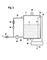
- Figure 3 shows an alternative with a tank and a Dosing system connected differential pressure sensor arrangement.
- a first pressure receiving element 77 At the The bottom of the tank is located, for example, centrally arranged, a first pressure receiving element 77, and in a height H above the bottom of the tank is a second Pressure receiving element 78 arranged.
- the tank is like this dimensioned that its maximum fill level at which the tank is defined as "full”, is smaller than the height H, see above that the second pressure sensing element even when the tank is full is above the liquid level.
- the second Pressure absorption element 78 is connected via a signal line 79 an evaluation circuit 80 is connected, as is the first Pressure recording element 77 connected to the circuit 80.
- At the output of circuit 81 At the output of circuit 81 is a pressure signal line connected with a signal input one not control unit shown is connected.
- the tank 3 has a filler neck 82 in the upper region.
- a line 88 is connected close to the ground, via a Feed pump 84 to an electrically via the control unit controllable metering valve 87 leads. Via the metering valve can the liquid contained in the tank, for example, in the exhaust tract of a motor vehicle are introduced.
- the control unit controls the Function of the electrically controllable feed pump, the electrically controllable metering valve and the electrically controllable pressure regulator depending on the signal of the Line pressure sensor 85 and not further here displayed data such as the speed, the Load of the motor vehicle engine and possibly other Signals from exhaust gas sensors arranged in the exhaust tract.
- the the signal applied to the pressure signal line 81 serves the purpose Control unit for detecting the level in the tank, so that a fuel level indicator can be controlled with it or that in time before reaching a certain lower Level warning in the dashboard of a truck can be issued, for example, a 32.5% Urea water solution needs to be refilled in order continues to meet the legal norms To ensure exhaust gas aftertreatment.
- the level and the pressure signal of the Pressure absorption element 77 are depending on Tank version specific and in a characteristic curve in the Control unit stored.
- the detection of the level is preferably done with the vehicle stationary when refueling or idle to avoid errors caused by sloshing Exclude reducing agents while driving. With increased Ambient temperature can reach up to 60 degrees Celsius the changed vapor pressure of the reducing agent Set increased pressure in the tank, which indicates the level signal would falsify on line 81 if it was on alone based on a signal from the first pressure recording element 77 would.
- the Consumption is based on the control data of the dosage or the dosing valve (dosing pressure, temperature, Control duration, control frequency etc.) determined and ongoing or at certain intervals from the last one actually measured level subtracted. The difference is then the new current level. With the vehicle stationary additionally via a pressure measurement in the tank Adjustment with regard to the fill level can be carried out. This increases the security when determining the Fill level for the reducing agent to fulfill statutory on-board diagnostic guidelines.
- the evaluation circuit 80 by a special configuration of the pressure receiving element 77 are replaced, in which the Signal line 79 replaced by an airtight pipe that prevailing in the upper area of the tank Gas pressure leads to the pressure receiving element 77.
- the second Pressure absorption element 78 is in this case by a Pressure medium replaced by that in the top Part of the tank protruding open end of the pipeline is formed is.
- the pressure receiving element 77 then generates at appropriate mechanical design an electrical Signal representing the pressure difference between the Liquid pressure at the bottom of the tank and the gas pressure in the corresponds to the upper area of the tank.
- pressure media for example an open end of a pressure transmitter deformable part (pressure sensor) for closing the open end of a pressure transmitter or a Understanding pressure element, which is an electrical Signal that corresponds to the pressure or Differential pressure correlated.
Landscapes
- Physics & Mathematics (AREA)
- Fluid Mechanics (AREA)
- General Physics & Mathematics (AREA)
- Measurement Of Levels Of Liquids Or Fluent Solid Materials (AREA)
- Exhaust Gas After Treatment (AREA)
- Measuring Fluid Pressure (AREA)
Applications Claiming Priority (4)
| Application Number | Priority Date | Filing Date | Title |
|---|---|---|---|
| DE10258864 | 2002-12-17 | ||
| DE10258864 | 2002-12-17 | ||
| DE10324009 | 2003-05-27 | ||
| DE10324009A DE10324009A1 (de) | 2002-12-17 | 2003-05-27 | Differenzdrucksensor zur Messung der Höhe der Flüssigkeit in einem Tank, insbesondere dem Harnstofftank eines Harnstoffdosiersystems |
Publications (3)
| Publication Number | Publication Date |
|---|---|
| EP1431722A2 true EP1431722A2 (fr) | 2004-06-23 |
| EP1431722A3 EP1431722A3 (fr) | 2005-11-16 |
| EP1431722B1 EP1431722B1 (fr) | 2010-10-13 |
Family
ID=32395022
Family Applications (1)
| Application Number | Title | Priority Date | Filing Date |
|---|---|---|---|
| EP20030019059 Expired - Lifetime EP1431722B1 (fr) | 2002-12-17 | 2003-08-22 | Capteur de pression différentielle pour la mesure du niveau du liquide dans un récipient |
Country Status (1)
| Country | Link |
|---|---|
| EP (1) | EP1431722B1 (fr) |
Cited By (3)
| Publication number | Priority date | Publication date | Assignee | Title |
|---|---|---|---|---|
| EP2995927A1 (fr) * | 2014-09-15 | 2016-03-16 | Hoppe Bordmesstechnik GmbH | Procede de determination d'une masse combustible et d'une densite de combustible |
| CN109029632A (zh) * | 2018-10-09 | 2018-12-18 | 洛阳源和科技有限公司 | 一种用于液位检测的差压控制器及测量方法 |
| EP3408471B1 (fr) | 2016-01-29 | 2020-03-04 | Zodiac Pool Care Europe | Robot nettoyeur de piscine et procédé d'utilisation d'un tel robot |
Families Citing this family (2)
| Publication number | Priority date | Publication date | Assignee | Title |
|---|---|---|---|---|
| CN104280094A (zh) * | 2014-10-22 | 2015-01-14 | 广东美的生活电器制造有限公司 | 水壶水位检测装置、水壶及水壶水位检测方法 |
| CN109764933B (zh) * | 2016-01-15 | 2020-11-27 | 庞极洲 | 一种差压传感装置及其构成的液位测量装置 |
Family Cites Families (5)
| Publication number | Priority date | Publication date | Assignee | Title |
|---|---|---|---|---|
| DE3714956A1 (de) * | 1987-05-06 | 1988-11-17 | Brombach Hansjoerg | Vorrichtung zum ueberwachen von regenueberlaeufen |
| DE3929344A1 (de) * | 1989-01-19 | 1990-07-26 | Holzer Walter | Fuellstandsanzeige |
| DE4112559A1 (de) * | 1991-04-17 | 1992-10-22 | Bosch Gmbh Robert | Fluessigkeitsbehaelter mit hydrostatischem fuellstandsmesser |
| US5245869A (en) * | 1991-10-01 | 1993-09-21 | Boston Advanced Technologies, Inc. | High accuracy mass sensor for monitoring fluid quantity in storage tanks |
| DE19638476A1 (de) * | 1995-09-20 | 1997-04-30 | Norbert Hoffmann | Füllstandssensor |
-
2003
- 2003-08-22 EP EP20030019059 patent/EP1431722B1/fr not_active Expired - Lifetime
Cited By (6)
| Publication number | Priority date | Publication date | Assignee | Title |
|---|---|---|---|---|
| EP2995927A1 (fr) * | 2014-09-15 | 2016-03-16 | Hoppe Bordmesstechnik GmbH | Procede de determination d'une masse combustible et d'une densite de combustible |
| CN105424080A (zh) * | 2014-09-15 | 2016-03-23 | 霍佩博德梅斯特赫尼克公司 | 测定燃料质量和燃料密度的方法 |
| CN105424080B (zh) * | 2014-09-15 | 2019-11-05 | 霍佩博德梅斯特赫尼克公司 | 测定燃料质量和燃料密度的方法 |
| EP3408471B1 (fr) | 2016-01-29 | 2020-03-04 | Zodiac Pool Care Europe | Robot nettoyeur de piscine et procédé d'utilisation d'un tel robot |
| CN109029632A (zh) * | 2018-10-09 | 2018-12-18 | 洛阳源和科技有限公司 | 一种用于液位检测的差压控制器及测量方法 |
| CN109029632B (zh) * | 2018-10-09 | 2025-01-03 | 洛阳源和科技有限公司 | 一种用于液位检测的差压控制器及测量方法 |
Also Published As
| Publication number | Publication date |
|---|---|
| EP1431722B1 (fr) | 2010-10-13 |
| EP1431722A3 (fr) | 2005-11-16 |
Similar Documents
| Publication | Publication Date | Title |
|---|---|---|
| DE10324009A1 (de) | Differenzdrucksensor zur Messung der Höhe der Flüssigkeit in einem Tank, insbesondere dem Harnstofftank eines Harnstoffdosiersystems | |
| EP1924825B1 (fr) | Unite de mesure a ultrasons presentant une fonction integree de determination de l'humidite | |
| DE3036347C2 (fr) | ||
| DE102016219834B4 (de) | Verfahren und Vorrichtung zur Überwachung des Tankinhalts eines Vorratstanks eines Abgasnachbehandlungssystems | |
| EP2705257B1 (fr) | Dispositif de séparation de media, en particulier accumulateur hydraulique, y compris appareil de mesure correspondant et méthode de mesure | |
| EP2035821B1 (fr) | Utilisation d'un dispositif dans usine de production de biogas et procédé de détermination ultrasonore des concentrations de constituants d'un mélange gazeux de biogaz. | |
| DE102010004615A1 (de) | Verfahren zur Bestimmung der aus einem Tank entnommenen Menge einer Flüssigkeit | |
| DE102013108158A1 (de) | Verfahren zur Herstellung eines Tanks mit einem kalibrierten Sensor | |
| DE112007000456T5 (de) | Eingetauchter Kraftstofffüllstandssensor | |
| DE102006013263A1 (de) | Verfahren zur Bestimmung einer Konzentration eines Bestandteils einer Flüssigkeit in einem Kraftfahrzeug | |
| EP2863215B1 (fr) | Dispositif de capteur destiné à détecter les propriétés d'un milieu fluidique | |
| WO2019105774A1 (fr) | Capteur ultrasonique, unité intégrée à un réservoir équipée d'un capteur ultrasonique | |
| DE10312100A1 (de) | Vorrichtung zur Messung eines Füllstandes einer Flüssigkeit in einem Behälter | |
| EP1431722A2 (fr) | Capteur de pression différentielle pour la mesure du niveau du liquide dans un récipient | |
| EP2488836A1 (fr) | Dispositif et procédé de mesure du niveau de remplissage dans des récipients de forme quelconque, notamment à l'intérieur de réservoirs de véhicule à moteur | |
| DE102014226137A1 (de) | Verfahren zur Bestimmung eines Füllstands eines Flüssigkeitstanks in einem Kraftfahrzeug | |
| DE112017004108T5 (de) | Messung der Eigenschaften und des Typs einer Flüssigkeit anhand einer temperaturabhängigen Änderungsrate einer Flüssigkeitsmessung | |
| DE102009038744A1 (de) | Anordnung zur Füllstandsmessung | |
| DE102016222849B4 (de) | Verfahren zur Kalibrierung einer Anzeige eines Füllstands | |
| DE102012001580A1 (de) | Verfahren zur Ermittlung eines Füllvolumens einer Verbrauchsflüssigkeit in einem Vorratsbehälter eines Kraftfahrzeugs | |
| DE102013109277B4 (de) | Vorrichtung zur Bestimmung oder Überwachung einer Prozessgröße | |
| DE19800054A1 (de) | Meßvorrichtung für eine Kraftstoffanzeige | |
| WO2012072666A1 (fr) | Procédé de détermination d'un volume instantané d'un liquide dans un réservoir, notamment pour un véhicule à moteur | |
| DE102011119673A1 (de) | Akustischer Wellenleiter-Sensor zur Bestimmung von Eigenschaften einer Flüssigkeit sowie seine Verwendung | |
| DE102020114636A1 (de) | Integrierter Sensor zur Erfassung eines minimalen Grenzstandes und eines Füllstandes, Anordnung eines solchen Sensors an einem Behälter und Verfahren zum Betreiben eines solchen Sensors |
Legal Events
| Date | Code | Title | Description |
|---|---|---|---|
| PUAI | Public reference made under article 153(3) epc to a published international application that has entered the european phase |
Free format text: ORIGINAL CODE: 0009012 |
|
| AK | Designated contracting states |
Kind code of ref document: A2 Designated state(s): AT BE BG CH CY CZ DE DK EE ES FI FR GB GR HU IE IT LI LU MC NL PT RO SE SI SK TR |
|
| AX | Request for extension of the european patent |
Extension state: AL LT LV MK |
|
| PUAL | Search report despatched |
Free format text: ORIGINAL CODE: 0009013 |
|
| AK | Designated contracting states |
Kind code of ref document: A3 Designated state(s): AT BE BG CH CY CZ DE DK EE ES FI FR GB GR HU IE IT LI LU MC NL PT RO SE SI SK TR |
|
| AX | Request for extension of the european patent |
Extension state: AL LT LV MK |
|
| RIC1 | Information provided on ipc code assigned before grant |
Ipc: 7G 01F 23/16 B Ipc: 7G 01F 23/18 A |
|
| 17P | Request for examination filed |
Effective date: 20060516 |
|
| AKX | Designation fees paid |
Designated state(s): DE FR GB IT |
|
| 17Q | First examination report despatched |
Effective date: 20061220 |
|
| GRAP | Despatch of communication of intention to grant a patent |
Free format text: ORIGINAL CODE: EPIDOSNIGR1 |
|
| GRAS | Grant fee paid |
Free format text: ORIGINAL CODE: EPIDOSNIGR3 |
|
| GRAA | (expected) grant |
Free format text: ORIGINAL CODE: 0009210 |
|
| AK | Designated contracting states |
Kind code of ref document: B1 Designated state(s): DE FR GB IT |
|
| REG | Reference to a national code |
Ref country code: GB Ref legal event code: FG4D Free format text: NOT ENGLISH |
|
| REF | Corresponds to: |
Ref document number: 50313179 Country of ref document: DE Date of ref document: 20101125 Kind code of ref document: P |
|
| PLBE | No opposition filed within time limit |
Free format text: ORIGINAL CODE: 0009261 |
|
| STAA | Information on the status of an ep patent application or granted ep patent |
Free format text: STATUS: NO OPPOSITION FILED WITHIN TIME LIMIT |
|
| 26N | No opposition filed |
Effective date: 20110714 |
|
| REG | Reference to a national code |
Ref country code: DE Ref legal event code: R097 Ref document number: 50313179 Country of ref document: DE Effective date: 20110714 |
|
| PG25 | Lapsed in a contracting state [announced via postgrant information from national office to epo] |
Ref country code: IT Free format text: LAPSE BECAUSE OF FAILURE TO SUBMIT A TRANSLATION OF THE DESCRIPTION OR TO PAY THE FEE WITHIN THE PRESCRIBED TIME-LIMIT Effective date: 20101013 |
|
| GBPC | Gb: european patent ceased through non-payment of renewal fee |
Effective date: 20110822 |
|
| REG | Reference to a national code |
Ref country code: FR Ref legal event code: ST Effective date: 20120430 |
|
| REG | Reference to a national code |
Ref country code: DE Ref legal event code: R119 Ref document number: 50313179 Country of ref document: DE Effective date: 20120301 |
|
| PG25 | Lapsed in a contracting state [announced via postgrant information from national office to epo] |
Ref country code: GB Free format text: LAPSE BECAUSE OF NON-PAYMENT OF DUE FEES Effective date: 20110822 Ref country code: FR Free format text: LAPSE BECAUSE OF NON-PAYMENT OF DUE FEES Effective date: 20110831 |
|
| PG25 | Lapsed in a contracting state [announced via postgrant information from national office to epo] |
Ref country code: DE Free format text: LAPSE BECAUSE OF NON-PAYMENT OF DUE FEES Effective date: 20120301 |