EP1431735A2 - Zusatz von Geruchstoffen zu Wasserstoff durch Verwendung von Geruchstoffen bei Wasserstoffspeichermaterialien - Google Patents
Zusatz von Geruchstoffen zu Wasserstoff durch Verwendung von Geruchstoffen bei Wasserstoffspeichermaterialien Download PDFInfo
- Publication number
- EP1431735A2 EP1431735A2 EP03028744A EP03028744A EP1431735A2 EP 1431735 A2 EP1431735 A2 EP 1431735A2 EP 03028744 A EP03028744 A EP 03028744A EP 03028744 A EP03028744 A EP 03028744A EP 1431735 A2 EP1431735 A2 EP 1431735A2
- Authority
- EP
- European Patent Office
- Prior art keywords
- odorant
- container
- interior volume
- hydrogen
- hydrogen gas
- Prior art date
- Legal status (The legal status is an assumption and is not a legal conclusion. Google has not performed a legal analysis and makes no representation as to the accuracy of the status listed.)
- Withdrawn
Links
Images
Classifications
-
- G—PHYSICS
- G01—MEASURING; TESTING
- G01M—TESTING STATIC OR DYNAMIC BALANCE OF MACHINES OR STRUCTURES; TESTING OF STRUCTURES OR APPARATUS, NOT OTHERWISE PROVIDED FOR
- G01M3/00—Investigating fluid-tightness of structures
- G01M3/02—Investigating fluid-tightness of structures by using fluid or vacuum
- G01M3/04—Investigating fluid-tightness of structures by using fluid or vacuum by detecting the presence of fluid at the leakage point
- G01M3/20—Investigating fluid-tightness of structures by using fluid or vacuum by detecting the presence of fluid at the leakage point using special tracer materials, e.g. dye, fluorescent material, radioactive material
-
- Y—GENERAL TAGGING OF NEW TECHNOLOGICAL DEVELOPMENTS; GENERAL TAGGING OF CROSS-SECTIONAL TECHNOLOGIES SPANNING OVER SEVERAL SECTIONS OF THE IPC; TECHNICAL SUBJECTS COVERED BY FORMER USPC CROSS-REFERENCE ART COLLECTIONS [XRACs] AND DIGESTS
- Y02—TECHNOLOGIES OR APPLICATIONS FOR MITIGATION OR ADAPTATION AGAINST CLIMATE CHANGE
- Y02E—REDUCTION OF GREENHOUSE GAS [GHG] EMISSIONS, RELATED TO ENERGY GENERATION, TRANSMISSION OR DISTRIBUTION
- Y02E60/00—Enabling technologies; Technologies with a potential or indirect contribution to GHG emissions mitigation
- Y02E60/30—Hydrogen technology
- Y02E60/32—Hydrogen storage
Definitions
- the present invention relates to fluid leak detection, and in particular to the leak detection of gases by odor generated by adding odiferous materials to the gases.
- hydrogen gas is emerging as a leading candidate for the fuel of choice.
- hydrogen may be obtained from an abundant, renewable, resource, water.
- Odorization of gases for leak detection is well known in the natural gas and petroleum gas industries.
- a paper by M.J. Usher Proc. Int. Scho. Hydrocarbon Meas . 73 rd , pages 743-48 (1998)) reviews the history, application, compounds, and safety practices in selecting and applying odorants in the natural gas industry. Mixing small quantities of odorants with gases is a substantially universal practice in natural and petroleum gases.
- a paper by I. Katuran Proc. Int. Sch. Hydrocarbon Meas., 64 th , pages 325-30 (1989) reports on natural gas odorants, their safety and handling precautions, handling techniques, and methods of adding odorants to gases.
- the PEM fuel cells are sulfur intolerant because sulfur compounds poison the noble metal catalysts used in these fuel cells. If sulfur-containing odorants are used, it would be necessary to remove sulfur containing materials, like mercaptan odorants, from the feed gas using materials like zinc oxide. The sulfur containing materials, like thiophenes, cannot be removed by zinc oxide and may require a hydrodesulfurization process, using hydrogen gas, to remove sulfur. This all will add to the cost of the process.
- a further complexity for hydrogen fuel comes from the nature of the hydrogen flame propagation. When gases burn in air, their flames propagate upwards with greater ease than they propagate downwards. This is primarily due to the natural convection of hot burnt gases in an upward direction. For petroleum gases, propane and methane, the upward and downward propagating lean limits of combustion are approximately the same. However, for hydrogen, since they differ by a factor of 2.5 , the amount of odorant needed for leak detection in hydrogen could be > 2.5 times that needed for methane or propane. The higher quantity of the odorant needed for hydrogen odor detection further complicates the sulfur poisoning problems for hydrogen gas used in the PEM fuel cells.
- gases included in this category are, for example, nitrogen, carbon monoxide, nitrogen trifluoride, ethylene oxide, carbon tetrafluoride and other perfluoro gases.
- odorant agents are sulfur compounds, e.g., mercaptans (tetrabutyl mercaptan, isopropyl mercaptan, normal propyl mercaptan, secondary butyl mercaptans, ethyl mercaptans, normal butyl mercaptan, etc.), thiophenes (tetrahydrothiophene), sulfides (dimethyl sulfide, methyl ethyl sulfide), etc.
- the chemicals used are also expected to have certain other attributes, such as low vapor pressure (high boiling point), low freezing point, low specific gravity so that they are fully dispersed in the gas, and appropriate thermal properties (e.g., they will not freeze at appropriate temperatures and will not cause over odorization in the hot weather).
- the general quality requirements, as specified for sulfur containing odorants in ISO/DIS 13734, are: (1) a cloud point of less than -30 degrees Celsius, (2) a boiling point of less than 130 degrees Celsius, and (3) evaporation residue of less than 0.2 %.
- odorants further will likely include an odorant concentration high enough to allow detection with a fuel gas concentration of 1/5 the lean limit of combustion. These requirements exist for natural gas (SAE J 1616, NFPA 52-1992) and petroleum gas (NFPA 58-1989).
- Natural gases are generally stored, distributed and used at relatively low pressures (50-500 psi). Hydrogen gas on the other hand is stored and transported at very elevated pressures (up to 10,000 psi). At normal operating temperatures, the odorants added to the high pressure gas storage tend to condense at the bottom of the storage vessels. This results in a non-uniform distribution and release of the odorants with the gas, causing a risk of over and under odorization, thereby taking the reliability away from the leak detection method by the human senses.
- a traditional method of using odorants is to meter a predetermined amount of the odorant into the gas stream either continuously in the pipeline or on a batch basis in the storage tanks.
- Electronic odorant injection systems (refer Zeck, DO53017A) have been designed that inject a prescribed amount of the odorants into the gas stream proportional to its flow rate.
- An electronic odorization system has five duties that it must perform to provide a safe source of natural gas. Combined, these duties insure that enough odorant is injected to make the gas properly detectable to human beings. These duties include:
- the typical full-featured electronic delivery odorant system should incorporate the following major components:
- Dispensing of the odorants may be done either in the gas tank or in the gas delivery pipes. Since the odorants are added to the bulk gas, their concentration varies throughout the tank. The odorant concentration in the delivered gas also is dependent on the speed at which the gas is dispensed. At low dispensing speeds, odorants get adsorbed on the delivery pipe walls, resulting in low odorant concentration in the bulk gas.
- odorants in hydrogen gas storage and delivery systems in which the odorants are distributed in the bulk gas in such a way that it maintains an almost constant concentration of the odorant in it throughout the supply of the gas.
- the present invention is an apparatus and a method for dispensing an odorant to a hydrogen gas. There are several embodiments of the apparatus and the method, as discussed below.
- a first embodiment of the apparatus for dispensing an odorant to a hydrogen gas includes at least one container, at least one odorant material, and at least one hydrogen storage material. Each container has an interior volume. The at least one odorant material, which has at least one detectable odor, is disposed in the interior volume of a first container. The at least one hydrogen storage material is disposed in the interior volume of the first container or in the interior volume of a second container.
- the odorant material and the hydrogen storage material are randomly mixed in the interior volume of the at least one container.
- at least a portion of the odorant material is in a first layer and at least a portion of the hydrogen storage material is in a second layer adjacent the first layer.
- the detectable odor is detectable by a sense of smell of a living being.
- At least a portion of the odorant material is sorbed on a sorbent.
- a form of energy is applied to the odorant material and to the hydrogen storage material and/or the at least one container is partially depressurized, thereby releasing an amount of the hydrogen gas from the hydrogen storage material and at least a portion of the odorant material from the sorbent.
- the portion of the odorant material released is a predetermined quantity.
- At least a portion of the odorant material is selected from a group consisting of derivatives of acrylic acid, alkyl esters of C 4 to C 7 , carboxylic acids, and combinations thereof.
- at least a portion of the odorant material is encapsulated by a polymer selected from a group consisting of a rubbery polymer, a glassy polymer, and combinations thereof, the rubbery polymer being selected from a group consisting of polydimethyl siloxanes, polyphasphazenes, and combinations thereof, and the glassy polymer being selected from a group consisting of polyimides, polysulfones, polyamides, polyarylates, polyolefins, polyetherketones, polycarbonates, and combinations thereof.
- Another embodiment of the apparatus of the present invention is similar to the first embodiment but includes a means for transmitting the hydrogen gas from the at least one container to a storage vessel or an end user.
- the means for transmitting comprises at least one conduit in fluid communication with the at least one container.
- the apparatus for dispensing an odorant to a hydrogen gas there are multiple elements.
- the first element is a first container having a first interior volume
- the second element is a second container having a second interior volume.
- At least one odorant material having at least one detectable odor is disposed in the first interior volume
- at least one hydrogen storage material is disposed in the second interior volume.
- Another element is at least one conduit having a first end in fluid communication with the first container and a second end in fluid communication with the second container.
- An additional element is a mixing means in fluid communication with the conduit. The mixing means is adapted to mix a flow of the hydrogen gas transmitted to the second end of the conduit from the second interior volume with a flow of at least a portion of the odorant material transmitted to the first end of the conduit from the first interior volume.
- Another embodiment is similar to the last embodiment described above but includes a means for transmitting a mixture of the hydrogen gas and the odorant material from the mixing means to a storage vessel or an end user.
- the means for transmitting comprises at least another conduit in fluid communication with the mixing means.
- the first embodiment is a method for dispensing an odorant to a hydrogen gas, which method includes multiple steps.
- the first step is to provide at least one container, each container having an interior volume.
- the second step is to provide at least one odorant material sorbed on a sorbent and disposed in the interior volume of a first container, the odorant material having at least one detectable odor.
- the third step is to provide at least one hydrogen storage material disposed in the interior volume of the first container or the interior volume of a second container.
- the fourth step is to apply a form of energy to the odorant material and to the hydrogen storage material and/or to partially depressurize the at least one container, thereby releasing an amount of the hydrogen gas from the hydrogen storage material and at least a portion of the odorant material from the sorbent.
- the portion of the odorant material released is a predetermined quantity.
- at least a portion of the odorant material is selected from a group consisting of derivatives of acrylic acid, alkyl esters of C 4 to C 7 , carboxylic acids, and combinations thereof.
- At least a portion of the odorant material is encapsulated by a polymer selected from a group consisting of a rubbery polymer, a glassy polymer, and combinations thereof, the rubbery polymer being selected from a group consisting of polydimethyl siloxanes, polyphasphazenes, and combinations thereof, and the glassy polymer being selected from a group consisting of polyimides, polysulfones, polyamides, polyarylates, polyolefins, polyetherketones, polycarbonates, and combinations thereof.
- Another embodiment of the method is similar to the first embodiment of the method but includes the further step of transmitting the hydrogen gas from the at least one container to a storage vessel or an end user.
- the first step is to provide a first container having a first interior volume.
- the second step is to provide a second container having a second interior volume.
- the third step is to provide at least one odorant material disposed in the first interior volume, the odorant material having at least one detectable odor.
- the fourth step is to provide at least one hydrogen storage material disposed in the second interior volume.
- the fifth step is to provide at least one conduit having a first end in fluid communication with the first container and a second end in fluid communication with the second container.
- the sixth step is to transmit a flow of the hydrogen gas to the second end of the conduit from the second interior volume.
- the seventh step is to transmit a flow of at least a portion of the odorant material to the first end of the conduit from the first interior volume.
- the eighth step is to withdraw from the conduit at least a portion of the hydrogen gas and at least a portion of the odorant material.
- the ninth step is to mix the hydrogen gas and the odorant material withdrawn from the conduit, thereby forming a mixture of the hydrogen gas and the odorant material.
- At least a portion of the odorant material is selected from a group consisting of derivatives of acrylic acid, alkyl esters of C 4 to C 7 , carboxylic acids, and combinations thereof.
- At least a portion of the odorant material is encapsulated by a polymer selected from a group consisting of a rubbery polymer, a glassy polymer, and combinations thereof, the rubbery polymer being selected from a group consisting of polydimethyl siloxanes, polyphasphazenes, and combinations thereof, and the glassy polymer being selected from a group consisting of polyimides, polysulfones, polyamides, polyarylates, polyolefins, polyetherketones, polycarbonates, and combinations thereof.
- Another embodiment of the method of the present invention is similar to the last embodiment described above but includes the further step of transmitting at least a portion of the mixture of the hydrogen gas and the odorant material to a storage vessel or an end user.
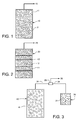
- FIG. 1 is a simplified, partial, cross-sectional view of a vessel containing odorant sorbents and hydrogen storage materials in accordance with one embodiment of the present invention
- FIG. 2 is a simplified, partial, cross-sectional view of layers of odorant sorbents and adjacent layers of hydrogen storage materials in accordance with another embodiment of the invention.
- FIG. 3 is a simplified, cross-sectional view of two vessels - - one containing odorant sorbents and the other containing hydrogen storage materials in accordance with another embodiment of the present invention.
- the present invention is directed to a system and method which can be used for the addition of odorants for use in gas leak detection.
- An odorant is contained within a sorption medium (sorbent) and is reversibly combined in various ways with a hydrogen storage material where the stored hydrogen is, at a particular temperature and H 2 pressure, in equilibrium with H 2 gas that is in contact with it.
- the odorant reversibly immobilized in a suitable carrier, is used in several different configurations in conjunction with the hydrogen storage material.
- the solid hydrogen storage material and the solid sorbed odorant are mixed randomly in one vessel or container.
- the hydrogen storage material and the sorbed odorant are arranged in discreet layers in the same vessel.
- the sorbed odorant and the hydrogen storage material are contained in two separate vessels connected to a common gas manifold.
- the gas exiting the vessel containing the hydrogen storage material will have acquired the amount of the odorant that is adequate to give the exiting gas an odor detectable by the human sense of smell.
- the hydrogen storage material may be a metal alloy which chemically reacts in a reversible manner with hydrogen to form a metal hydride.
- Metal hydrides are solids which contain hydrogen in a chemically bound form, from which H 2 can be released either by heating or by reducing the partial pressure of the H 2 above the solid, or by a combination of the two processes. See G. Sandrock in J. Alloys and Compounds 293-295 (1999) 877-888.
- the hydrogen storage material may be a composition that is based on carbon, such as carbon nanotubes or carbon-metal hydride compositions. See, for example, EP 1 209119 A2 (2002) by Air Products and Chemicals, Inc.
- Any practical hydrogen storage material functions by having a strong physical or chemical, yet reversible, interaction with the gas.
- Sulfur containing compounds which are the most commonly used odorants for natural gas, will likely interfere with this hydrocarbon binding mechanism, thus inhibiting or even precluding the storage of hydrogen.
- non-sulfur containing odorants are highly preferred, including compounds such as the acrylic acid derivatives identified in WO 00/11120, and the butyric, vaoleric, and caporic acid esters that are advocated as fuel odorants in JP 2002 060766-A to Nippon Oil Co. Ltd.
- the odorant material is sorped or occluded in an appropriate solid medium hydrogen storage material and a predetermined quantity of the sorbed odorant material is mixed with the hydrogen storage materials from which hydrogen is being generated.
- a key feature of the invention is that it offers a high degree of dispersion of the sorbed odorant through the bed of hydrogen carrying material as well as a large interfacial surface area between the two, such that the solid-occluded odorant is more uniformly delivered from the gas container.
- FIG.1 shows a simplified, partial cross section of a vessel 10 containing odorant sorbent 11 and particles of hydrogen storage material 12.
- the hydrogen storage material particles and the particles containing the sorbed odorants are distributed randomly in the vessel 10.
- hydrogen is released from its carrier hydrogen storage material 12 and a predetermined quantity of odorant is released from the odorant sorbent 11.
- the co-released hydrogen gas and odorant are thus mixed in the sorbent bed vessel and transmitted from this vessel 10 to an outlet 15.
- FIG. 2 shows a simplified, partial cross section of a vessel 20 in which odorant sorbent 11 and the particles of hydrogen storage material 12 are placed in an orderly fashion in layers.
- a distribution mesh 13 may be used between adjacent layers.
- FIG 3 shows a simplified, partial cross section of hydrogen storage material containing vessel 40 and an odorant sorbent containing vessel 30.
- the hydrogen storage material 41 and the odorant sorbent 31 are placed in two separate vessels (30, 40) which may or may not have a common heating source.
- a common manifold 34 connects the two vessels.
- Example 1 Preparation of a sorbed or occluded odorant.
- a solution of the odoriferous material in a volatile solvent is used to fill the pores of an appropriate porous material, such as a sorption clay, zeolites, carbon, a cellulosic or polymeric sorption media.
- the volatile solvent is then evaporated leaving behind the adsorbed odorant.
- the odorants can also be encapsulated in an appropriate organic polymer medium.
- the odoriferous material solution is made at a concentration of 0.01 % w/w to 90% w/w either in aqueous or non aqueous solvent/solvent mixtures of relatively high volatility solvents in which the odoriferous materials are soluble.
- the thin encapsulating layer is formed on the odorant film, for example, using a rubbery polymer such as polydimethyl siloxane amongst other rubbery materials and glassy polymers such as polyimides, polysulfones, polyamides, polyarylates, polyolefins, and the like.
- a rubbery polymer such as polydimethyl siloxane amongst other rubbery materials and glassy polymers such as polyimides, polysulfones, polyamides, polyarylates, polyolefins, and the like.
- an over coating is then made by dissolving a rubbery or glassy film forming polymer in an appropriate volatile solvent at a concentration ranging from 0.1 % to 10 % solution depending on the thickness
- Example 2 The odorant material can be sorbed with an appropriate substrate where it exists in a liquid condensed form and is held therein by capillary action. This odorant containing sorbed material is placed in the storage vessel in a predetermined quantity. At the temperature and pressure of the gas, the odorant material establishes equilibrium with the gas and provides the needed concentration that is required to generate an odor in the leaking gas.
- Example 3 The odorant sorbed on an appropriate medium is mixed in a pre-determined ratio with the hydrogen storage material.
- the mixing of the two components is in a random fashion as shown in Figure 1.
- the hydrogen storage material is heated to release hydrogen, the required quantity of the odorant is released as well, thereby mixing the hydrogen gas with the non de-sorbed odorant in such a way that any leaking hydrogen from the system has a detectible specific odor associated with it.
- Example 4 The odorant sorbed within an appropriate medium is placed in discrete layers along with the hydrogen storage material layers in a fashion as shown in Figure 2 in a pre-determined ratio.
- the hydrogen storage material is heated and/or the pressure is lowered to release hydrogen, it releases with it the required quantity of the odorant as well, thereby mixing the hydrogen gas with the sorbent in such a way that the leaking hydrogen has a specific odor associated with it.
- Example 5 The sorbent and the hydrogen storage material are placed in separate vessels as shown in Figure 3. Both can be maintained at the same temperature or at different temperatures to generate hydrogen and the odorant. The two are mixed in a mixing tee or the like to provide a mixture of hydrogen and odorant.
Landscapes
- Physics & Mathematics (AREA)
- General Physics & Mathematics (AREA)
- Filling Or Discharging Of Gas Storage Vessels (AREA)
- Separation Of Gases By Adsorption (AREA)
- Hydrogen, Water And Hydrids (AREA)
- Solid-Sorbent Or Filter-Aiding Compositions (AREA)
Applications Claiming Priority (2)
| Application Number | Priority Date | Filing Date | Title |
|---|---|---|---|
| US10/321,326 US7024869B2 (en) | 2002-12-16 | 2002-12-16 | Addition of odorants to hydrogen by incorporating odorants with hydrogen storage materials |
| US321326 | 2002-12-16 |
Publications (2)
| Publication Number | Publication Date |
|---|---|
| EP1431735A2 true EP1431735A2 (de) | 2004-06-23 |
| EP1431735A3 EP1431735A3 (de) | 2006-01-25 |
Family
ID=32393002
Family Applications (1)
| Application Number | Title | Priority Date | Filing Date |
|---|---|---|---|
| EP03028744A Withdrawn EP1431735A3 (de) | 2002-12-16 | 2003-12-12 | Zusatz von Geruchstoffen zu Wasserstoff durch Verwendung von Geruchstoffen bei Wasserstoffspeichermaterialien |
Country Status (3)
| Country | Link |
|---|---|
| US (1) | US7024869B2 (de) |
| EP (1) | EP1431735A3 (de) |
| CA (1) | CA2452466C (de) |
Cited By (1)
| Publication number | Priority date | Publication date | Assignee | Title |
|---|---|---|---|---|
| EP1464693A3 (de) * | 2003-04-01 | 2006-03-01 | Hewlett-Packard Development Company, L.P. | Leckdetektion bei Brennstoffzellen |
Families Citing this family (15)
| Publication number | Priority date | Publication date | Assignee | Title |
|---|---|---|---|---|
| JP5145667B2 (ja) * | 2006-08-03 | 2013-02-20 | トヨタ自動車株式会社 | 水素供給装置 |
| US7915047B2 (en) | 2007-11-19 | 2011-03-29 | Los Alamos National Security, Llc | Coating for leak detection and method |
| DE102009000508A1 (de) * | 2008-07-29 | 2010-02-04 | Robert Bosch Gmbh | Speicherbehälter und Verfahren zum verlustreduzierten Speichern eines Brennstoffs |
| US11268875B2 (en) * | 2016-11-22 | 2022-03-08 | Redline Detection, Llc | Method and apparatus for fluid leak detection |
| US12251991B2 (en) | 2020-08-20 | 2025-03-18 | Denso International America, Inc. | Humidity control for olfaction sensors |
| US11760169B2 (en) | 2020-08-20 | 2023-09-19 | Denso International America, Inc. | Particulate control systems and methods for olfaction sensors |
| US11636870B2 (en) | 2020-08-20 | 2023-04-25 | Denso International America, Inc. | Smoking cessation systems and methods |
| US11828210B2 (en) | 2020-08-20 | 2023-11-28 | Denso International America, Inc. | Diagnostic systems and methods of vehicles using olfaction |
| US11932080B2 (en) | 2020-08-20 | 2024-03-19 | Denso International America, Inc. | Diagnostic and recirculation control systems and methods |
| US12017506B2 (en) | 2020-08-20 | 2024-06-25 | Denso International America, Inc. | Passenger cabin air control systems and methods |
| US11881093B2 (en) | 2020-08-20 | 2024-01-23 | Denso International America, Inc. | Systems and methods for identifying smoking in vehicles |
| US11813926B2 (en) | 2020-08-20 | 2023-11-14 | Denso International America, Inc. | Binding agent and olfaction sensor |
| US12269315B2 (en) | 2020-08-20 | 2025-04-08 | Denso International America, Inc. | Systems and methods for measuring and managing odor brought into rental vehicles |
| US11760170B2 (en) | 2020-08-20 | 2023-09-19 | Denso International America, Inc. | Olfaction sensor preservation systems and methods |
| US12377711B2 (en) | 2020-08-20 | 2025-08-05 | Denso International America, Inc. | Vehicle feature control systems and methods based on smoking |
Family Cites Families (8)
| Publication number | Priority date | Publication date | Assignee | Title |
|---|---|---|---|---|
| US3140156A (en) * | 1960-06-09 | 1964-07-07 | Auergesellschaft Gmbh | Canister with olfactory warner |
| US3907515A (en) * | 1972-10-02 | 1975-09-23 | San Diego Gas & Electric Co | Apparatus for odorizing liquid natural gas |
| US5792661A (en) * | 1997-03-31 | 1998-08-11 | The United States Of America As Represented By The Secretary Of The Army | Method of detecting leaks in sealed containers |
| BR9911824A (pt) * | 1998-07-03 | 2001-03-27 | Toyota Motor Co Ltd | Método e sistema de armazenamento de gás, e material de oclusão para gás |
| DE19837066A1 (de) | 1998-08-17 | 2000-02-24 | Haarmann & Reimer Gmbh | Odorierung von Gas |
| US6063632A (en) | 1998-11-12 | 2000-05-16 | Perkins; Gary | Water leak detection |
| JP2002029701A (ja) * | 2000-07-10 | 2002-01-29 | Toyota Motor Corp | 水素供給装置および該水素供給装置を備える燃料電池装置、並びに水素検出方法 |
| US6672077B1 (en) * | 2001-12-11 | 2004-01-06 | Nanomix, Inc. | Hydrogen storage in nanostructure with physisorption |
-
2002
- 2002-12-16 US US10/321,326 patent/US7024869B2/en not_active Expired - Fee Related
-
2003
- 2003-12-09 CA CA002452466A patent/CA2452466C/en not_active Expired - Fee Related
- 2003-12-12 EP EP03028744A patent/EP1431735A3/de not_active Withdrawn
Cited By (1)
| Publication number | Priority date | Publication date | Assignee | Title |
|---|---|---|---|---|
| EP1464693A3 (de) * | 2003-04-01 | 2006-03-01 | Hewlett-Packard Development Company, L.P. | Leckdetektion bei Brennstoffzellen |
Also Published As
| Publication number | Publication date |
|---|---|
| CA2452466C (en) | 2007-12-11 |
| EP1431735A3 (de) | 2006-01-25 |
| US7024869B2 (en) | 2006-04-11 |
| US20040126889A1 (en) | 2004-07-01 |
| CA2452466A1 (en) | 2004-06-16 |
Similar Documents
| Publication | Publication Date | Title |
|---|---|---|
| US20040126888A1 (en) | Double walled vessels for odorant containments | |
| US7024869B2 (en) | Addition of odorants to hydrogen by incorporating odorants with hydrogen storage materials | |
| US7192459B2 (en) | Addition of odorants to gases for leak detection | |
| US7229831B2 (en) | Leak site odorization for gas leak detection | |
| US7811688B2 (en) | Hydrogen odorants and odorant selection method | |
| US20040115818A1 (en) | Leak detection by reactions at the leak site | |
| WO2009067146A1 (en) | Coating for leak detection and method | |
| US6820464B2 (en) | Odorized seals for the detection of gas leak | |
| WO2008156191A1 (ja) | ガス用着臭剤およびそのガス用着臭剤を用いた都市ガス製造方法 | |
| EP0875714A1 (de) | Verfahren und Vorrichtung zur Behandlung vom Verdampfungsverlustgas in einem Tieftemperatur Flüssigkeitsbehälter | |
| Laine et al. | Permeability of polyethylene film to organic vapors | |
| CA2452462A1 (en) | Double walled vessels for odorant containments | |
| Glushkov et al. | Kinetic properties of gas-phase combustion of gel fuels based on oil-filled cryogels | |
| JP3522493B2 (ja) | 可搬式兼取替式燃料ガスタンク | |
| KR100264820B1 (ko) | 가스연료흡수저장고형연료및그제조방법 | |
| JP4598896B2 (ja) | 燃料電池システム用燃料 | |
| KR20200050099A (ko) | 부취제 주입 장치 | |
| JP2025079540A (ja) | 油膜付燃料及び非混和性油脂 | |
| KR200150179Y1 (ko) | 카세트식 가스봄베 | |
| cycle XXXIII | Department of Industrial Engineering | |
| CA2196941A1 (en) | Dual containment assembly | |
| JP3801874B2 (ja) | 燃料ガスへの着臭剤添加方法 | |
| Pannikottu et al. | A New Fuel Permeation Test Set-up for SAE J1737 to Determine Hydrocarbon Liquid Losses Through Tubes, Hoses and Fittings | |
| Porter | MARINE INERT GAS SYSTEMS | |
| Highway et al. | DIRECTORATE FOR ENGINEERING SCIENCES RUlE:\lAKI}; GADMlN. PRCDG |
Legal Events
| Date | Code | Title | Description |
|---|---|---|---|
| PUAI | Public reference made under article 153(3) epc to a published international application that has entered the european phase |
Free format text: ORIGINAL CODE: 0009012 |
|
| AK | Designated contracting states |
Kind code of ref document: A2 Designated state(s): AT BE BG CH CY CZ DE DK EE ES FI FR GB GR HU IE IT LI LU MC NL PT RO SE SI SK TR |
|
| AX | Request for extension of the european patent |
Extension state: AL LT LV MK |
|
| PUAL | Search report despatched |
Free format text: ORIGINAL CODE: 0009013 |
|
| AK | Designated contracting states |
Kind code of ref document: A3 Designated state(s): AT BE BG CH CY CZ DE DK EE ES FI FR GB GR HU IE IT LI LU MC NL PT RO SE SI SK TR |
|
| AX | Request for extension of the european patent |
Extension state: AL LT LV MK |
|
| 17P | Request for examination filed |
Effective date: 20060209 |
|
| AKX | Designation fees paid |
Designated state(s): AT BE BG CH CY CZ DE DK EE ES FI FR GB GR HU IE IT LI LU MC NL PT RO SE SI SK TR |
|
| STAA | Information on the status of an ep patent application or granted ep patent |
Free format text: STATUS: THE APPLICATION IS DEEMED TO BE WITHDRAWN |
|
| 18D | Application deemed to be withdrawn |
Effective date: 20100701 |