EP1431736A2 - Odorisation d'un lieu de fuite pour la détection d'une fuite de gaz - Google Patents
Odorisation d'un lieu de fuite pour la détection d'une fuite de gaz Download PDFInfo
- Publication number
- EP1431736A2 EP1431736A2 EP03028745A EP03028745A EP1431736A2 EP 1431736 A2 EP1431736 A2 EP 1431736A2 EP 03028745 A EP03028745 A EP 03028745A EP 03028745 A EP03028745 A EP 03028745A EP 1431736 A2 EP1431736 A2 EP 1431736A2
- Authority
- EP
- European Patent Office
- Prior art keywords
- odorant
- layer
- semi
- wall
- permeable material
- Prior art date
- Legal status (The legal status is an assumption and is not a legal conclusion. Google has not performed a legal analysis and makes no representation as to the accuracy of the status listed.)
- Withdrawn
Links
- 238000001514 detection method Methods 0.000 title description 14
- 239000003205 fragrance Substances 0.000 claims abstract description 239
- 239000000463 material Substances 0.000 claims abstract description 186
- 239000012530 fluid Substances 0.000 claims abstract description 40
- 239000007789 gas Substances 0.000 claims description 130
- 238000000034 method Methods 0.000 claims description 43
- 239000012298 atmosphere Substances 0.000 claims description 36
- 229920000642 polymer Polymers 0.000 claims description 34
- 230000008786 sensory perception of smell Effects 0.000 claims description 24
- UFHFLCQGNIYNRP-UHFFFAOYSA-N Hydrogen Chemical compound [H][H] UFHFLCQGNIYNRP-UHFFFAOYSA-N 0.000 claims description 20
- 229910052739 hydrogen Inorganic materials 0.000 claims description 20
- 239000001257 hydrogen Substances 0.000 claims description 19
- QMMFVYPAHWMCMS-UHFFFAOYSA-N Dimethyl sulfide Chemical compound CSC QMMFVYPAHWMCMS-UHFFFAOYSA-N 0.000 claims description 18
- WQAQPCDUOCURKW-UHFFFAOYSA-N butanethiol Chemical group CCCCS WQAQPCDUOCURKW-UHFFFAOYSA-N 0.000 claims description 18
- 229920001971 elastomer Polymers 0.000 claims description 13
- SUVIGLJNEAMWEG-UHFFFAOYSA-N propane-1-thiol Chemical compound CCCS SUVIGLJNEAMWEG-UHFFFAOYSA-N 0.000 claims description 12
- KJRCEJOSASVSRA-UHFFFAOYSA-N propane-2-thiol Chemical compound CC(C)S KJRCEJOSASVSRA-UHFFFAOYSA-N 0.000 claims description 12
- RWSOTUBLDIXVET-UHFFFAOYSA-N Dihydrogen sulfide Chemical class S RWSOTUBLDIXVET-UHFFFAOYSA-N 0.000 claims description 8
- LSDPWZHWYPCBBB-UHFFFAOYSA-N Methanethiol Chemical compound SC LSDPWZHWYPCBBB-UHFFFAOYSA-N 0.000 claims description 7
- 239000004952 Polyamide Substances 0.000 claims description 7
- 239000004642 Polyimide Substances 0.000 claims description 7
- 229920002492 poly(sulfone) Polymers 0.000 claims description 7
- 229920002647 polyamide Polymers 0.000 claims description 7
- 229920001230 polyarylate Polymers 0.000 claims description 7
- 229920001721 polyimide Polymers 0.000 claims description 7
- 229930192474 thiophene Natural products 0.000 claims description 7
- 150000003577 thiophenes Chemical class 0.000 claims description 7
- NIXOWILDQLNWCW-UHFFFAOYSA-N Acrylic acid Chemical class OC(=O)C=C NIXOWILDQLNWCW-UHFFFAOYSA-N 0.000 claims description 6
- XYWDPYKBIRQXQS-UHFFFAOYSA-N di-isopropyl sulphide Natural products CC(C)SC(C)C XYWDPYKBIRQXQS-UHFFFAOYSA-N 0.000 claims description 6
- 235000013870 dimethyl polysiloxane Nutrition 0.000 claims description 6
- DNJIEGIFACGWOD-UHFFFAOYSA-N ethanethiol Chemical group CCS DNJIEGIFACGWOD-UHFFFAOYSA-N 0.000 claims description 6
- WXEHBUMAEPOYKP-UHFFFAOYSA-N methylsulfanylethane Chemical compound CCSC WXEHBUMAEPOYKP-UHFFFAOYSA-N 0.000 claims description 6
- 229920000435 poly(dimethylsiloxane) Polymers 0.000 claims description 6
- 229920000515 polycarbonate Polymers 0.000 claims description 6
- 239000004417 polycarbonate Substances 0.000 claims description 6
- RAOIDOHSFRTOEL-UHFFFAOYSA-N tetrahydrothiophene Chemical compound C1CCSC1 RAOIDOHSFRTOEL-UHFFFAOYSA-N 0.000 claims description 6
- 150000003568 thioethers Chemical class 0.000 claims description 6
- 150000005215 alkyl ethers Chemical class 0.000 claims description 5
- 150000001735 carboxylic acids Chemical class 0.000 claims description 5
- 229920001643 poly(ether ketone) Polymers 0.000 claims description 5
- 229920000098 polyolefin Polymers 0.000 claims description 5
- 239000000758 substrate Substances 0.000 claims description 2
- 239000010410 layer Substances 0.000 description 144
- 238000000576 coating method Methods 0.000 description 69
- 239000011248 coating agent Substances 0.000 description 54
- 239000002904 solvent Substances 0.000 description 25
- 235000019645 odor Nutrition 0.000 description 23
- VNWKTOKETHGBQD-UHFFFAOYSA-N methane Chemical compound C VNWKTOKETHGBQD-UHFFFAOYSA-N 0.000 description 20
- 239000000446 fuel Substances 0.000 description 13
- 239000012528 membrane Substances 0.000 description 10
- 239000000203 mixture Substances 0.000 description 10
- NINIDFKCEFEMDL-UHFFFAOYSA-N Sulfur Chemical compound [S] NINIDFKCEFEMDL-UHFFFAOYSA-N 0.000 description 9
- 229910052717 sulfur Inorganic materials 0.000 description 9
- 239000011593 sulfur Substances 0.000 description 9
- 239000003345 natural gas Substances 0.000 description 8
- 239000010408 film Substances 0.000 description 6
- 239000003208 petroleum Substances 0.000 description 6
- 238000001704 evaporation Methods 0.000 description 5
- 239000007788 liquid Substances 0.000 description 5
- -1 perfluoro Chemical group 0.000 description 5
- 239000011148 porous material Substances 0.000 description 5
- 239000011877 solvent mixture Substances 0.000 description 5
- ATUOYWHBWRKTHZ-UHFFFAOYSA-N Propane Chemical compound CCC ATUOYWHBWRKTHZ-UHFFFAOYSA-N 0.000 description 4
- XLOMVQKBTHCTTD-UHFFFAOYSA-N Zinc monoxide Chemical compound [Zn]=O XLOMVQKBTHCTTD-UHFFFAOYSA-N 0.000 description 4
- 239000012466 permeate Substances 0.000 description 4
- 239000007787 solid Substances 0.000 description 4
- 239000004215 Carbon black (E152) Substances 0.000 description 3
- 230000008020 evaporation Effects 0.000 description 3
- 229930195733 hydrocarbon Natural products 0.000 description 3
- 150000002430 hydrocarbons Chemical class 0.000 description 3
- 229920006254 polymer film Polymers 0.000 description 3
- 230000008569 process Effects 0.000 description 3
- 239000002356 single layer Substances 0.000 description 3
- 238000001179 sorption measurement Methods 0.000 description 3
- 239000000126 substance Substances 0.000 description 3
- XLYOFNOQVPJJNP-UHFFFAOYSA-N water Substances O XLYOFNOQVPJJNP-UHFFFAOYSA-N 0.000 description 3
- IJGRMHOSHXDMSA-UHFFFAOYSA-N Atomic nitrogen Chemical compound N#N IJGRMHOSHXDMSA-UHFFFAOYSA-N 0.000 description 2
- 230000008901 benefit Effects 0.000 description 2
- 238000009835 boiling Methods 0.000 description 2
- 239000003054 catalyst Substances 0.000 description 2
- 238000005345 coagulation Methods 0.000 description 2
- 230000015271 coagulation Effects 0.000 description 2
- 229920001688 coating polymer Polymers 0.000 description 2
- 238000002485 combustion reaction Methods 0.000 description 2
- 150000001875 compounds Chemical class 0.000 description 2
- 238000004132 cross linking Methods 0.000 description 2
- 238000005538 encapsulation Methods 0.000 description 2
- 150000002431 hydrogen Chemical class 0.000 description 2
- 239000011261 inert gas Substances 0.000 description 2
- 230000009965 odorless effect Effects 0.000 description 2
- 239000003209 petroleum derivative Substances 0.000 description 2
- 239000002574 poison Substances 0.000 description 2
- 231100000614 poison Toxicity 0.000 description 2
- 239000001294 propane Substances 0.000 description 2
- 238000012552 review Methods 0.000 description 2
- 239000002594 sorbent Substances 0.000 description 2
- 150000003464 sulfur compounds Chemical class 0.000 description 2
- 239000010409 thin film Substances 0.000 description 2
- 239000011787 zinc oxide Substances 0.000 description 2
- SMZOUWXMTYCWNB-UHFFFAOYSA-N 2-(2-methoxy-5-methylphenyl)ethanamine Chemical compound COC1=CC=C(C)C=C1CCN SMZOUWXMTYCWNB-UHFFFAOYSA-N 0.000 description 1
- UGFAIRIUMAVXCW-UHFFFAOYSA-N Carbon monoxide Chemical compound [O+]#[C-] UGFAIRIUMAVXCW-UHFFFAOYSA-N 0.000 description 1
- IAYPIBMASNFSPL-UHFFFAOYSA-N Ethylene oxide Chemical compound C1CO1 IAYPIBMASNFSPL-UHFFFAOYSA-N 0.000 description 1
- 229920002125 Sokalan® Polymers 0.000 description 1
- 239000003125 aqueous solvent Substances 0.000 description 1
- 230000015572 biosynthetic process Effects 0.000 description 1
- 229910002091 carbon monoxide Inorganic materials 0.000 description 1
- 230000008859 change Effects 0.000 description 1
- 238000006243 chemical reaction Methods 0.000 description 1
- 239000003795 chemical substances by application Substances 0.000 description 1
- 239000000701 coagulant Substances 0.000 description 1
- 239000011247 coating layer Substances 0.000 description 1
- 238000009833 condensation Methods 0.000 description 1
- 230000005494 condensation Effects 0.000 description 1
- 239000003431 cross linking reagent Substances 0.000 description 1
- 230000007547 defect Effects 0.000 description 1
- 238000006477 desulfuration reaction Methods 0.000 description 1
- 230000023556 desulfurization Effects 0.000 description 1
- 238000011161 development Methods 0.000 description 1
- 239000004205 dimethyl polysiloxane Substances 0.000 description 1
- 238000001035 drying Methods 0.000 description 1
- 239000000428 dust Substances 0.000 description 1
- 238000005516 engineering process Methods 0.000 description 1
- 238000009472 formulation Methods 0.000 description 1
- 238000007710 freezing Methods 0.000 description 1
- 230000008014 freezing Effects 0.000 description 1
- 239000002737 fuel gas Substances 0.000 description 1
- 230000006870 function Effects 0.000 description 1
- 230000005484 gravity Effects 0.000 description 1
- 238000010438 heat treatment Methods 0.000 description 1
- 230000000873 masking effect Effects 0.000 description 1
- 230000007246 mechanism Effects 0.000 description 1
- 238000002156 mixing Methods 0.000 description 1
- 230000004048 modification Effects 0.000 description 1
- 238000012986 modification Methods 0.000 description 1
- QKCGXXHCELUCKW-UHFFFAOYSA-N n-[4-[4-(dinaphthalen-2-ylamino)phenyl]phenyl]-n-naphthalen-2-ylnaphthalen-2-amine Chemical compound C1=CC=CC2=CC(N(C=3C=CC(=CC=3)C=3C=CC(=CC=3)N(C=3C=C4C=CC=CC4=CC=3)C=3C=C4C=CC=CC4=CC=3)C3=CC4=CC=CC=C4C=C3)=CC=C21 QKCGXXHCELUCKW-UHFFFAOYSA-N 0.000 description 1
- 229910052757 nitrogen Inorganic materials 0.000 description 1
- 229910017464 nitrogen compound Inorganic materials 0.000 description 1
- 150000002830 nitrogen compounds Chemical class 0.000 description 1
- 229910000510 noble metal Inorganic materials 0.000 description 1
- 231100000572 poisoning Toxicity 0.000 description 1
- 230000000607 poisoning effect Effects 0.000 description 1
- 239000004584 polyacrylic acid Substances 0.000 description 1
- 239000005518 polymer electrolyte Substances 0.000 description 1
- 229920002689 polyvinyl acetate Polymers 0.000 description 1
- 239000011118 polyvinyl acetate Substances 0.000 description 1
- 229920002451 polyvinyl alcohol Polymers 0.000 description 1
- 235000019422 polyvinyl alcohol Nutrition 0.000 description 1
- 239000000843 powder Substances 0.000 description 1
- 238000010248 power generation Methods 0.000 description 1
- 230000001902 propagating effect Effects 0.000 description 1
- 238000002407 reforming Methods 0.000 description 1
- 238000011160 research Methods 0.000 description 1
- 238000005201 scrubbing Methods 0.000 description 1
- 238000000926 separation method Methods 0.000 description 1
- 238000005507 spraying Methods 0.000 description 1
- 239000004094 surface-active agent Substances 0.000 description 1
- 229920001059 synthetic polymer Polymers 0.000 description 1
- TXEYQDLBPFQVAA-UHFFFAOYSA-N tetrafluoromethane Chemical compound FC(F)(F)F TXEYQDLBPFQVAA-UHFFFAOYSA-N 0.000 description 1
- 231100000331 toxic Toxicity 0.000 description 1
- 230000002588 toxic effect Effects 0.000 description 1
- 239000002341 toxic gas Substances 0.000 description 1
- 229920003169 water-soluble polymer Polymers 0.000 description 1
- 239000010457 zeolite Substances 0.000 description 1
Images
Classifications
-
- G—PHYSICS
- G01—MEASURING; TESTING
- G01M—TESTING STATIC OR DYNAMIC BALANCE OF MACHINES OR STRUCTURES; TESTING OF STRUCTURES OR APPARATUS, NOT OTHERWISE PROVIDED FOR
- G01M3/00—Investigating fluid-tightness of structures
- G01M3/02—Investigating fluid-tightness of structures by using fluid or vacuum
- G01M3/04—Investigating fluid-tightness of structures by using fluid or vacuum by detecting the presence of fluid at the leakage point
- G01M3/20—Investigating fluid-tightness of structures by using fluid or vacuum by detecting the presence of fluid at the leakage point using special tracer materials, e.g. dye, fluorescent material, radioactive material
- G01M3/22—Investigating fluid-tightness of structures by using fluid or vacuum by detecting the presence of fluid at the leakage point using special tracer materials, e.g. dye, fluorescent material, radioactive material for pipes, cables or tubes; for pipe joints or seals; for valves; for welds; for containers, e.g. radiators
- G01M3/223—Investigating fluid-tightness of structures by using fluid or vacuum by detecting the presence of fluid at the leakage point using special tracer materials, e.g. dye, fluorescent material, radioactive material for pipes, cables or tubes; for pipe joints or seals; for valves; for welds; for containers, e.g. radiators for pipe joints or seals
Definitions
- the present invention relates to fluid leak detection, and in particular to the leak detection of gases by odor generated by adding odiferous materials to the gases at the leak site.
- hydrogen gas is emerging as a leading candidate for the fuel of choice.
- hydrogen may be obtained from an abundant, renewable, resource, water.
- Odorization of gases for leak detection is well known in the natural gas and petroleum gas industries.
- a paper by M.J. Usher Proc. Int. Scho. Hydrocarbon Meas. 73 rd , pages 743-48 (1998)) reviews the history, application, compounds, and safety practices in selecting and applying odorants in the natural gas industry. Mixing small quantities of odorants with gases is a substantially universal practice in natural and petroleum gases.
- a paper by I. Katuran Proc. Int. Sch. Hydrocarbon Meas ., 64 th , pages 325-30 (1989) reports on natural gas odorants, their safety and handling precautions, handling techniques, and methods of adding odorants to gases.
- the PEM fuel cells are sulfur intolerant because sulfur compounds poison the noble metal catalysts used in these fuel cells. If sulfur-containing odorants are used, it would be necessary to remove sulfur containing materials, like mercaptan odorants, from the feed gas using materials like zinc oxide. The sulfur containing materials, like thiophenes, cannot be removed by zinc oxide and may require a hydrodesulfurization process, using hydrogen gas, to remove sulfur. This all will add to the cost of the process.
- a further complexity for hydrogen fuel comes from the nature of the hydrogen flame propagation. When gases burn in air, their flames propagate upwards with greater ease than they propagate downwards. This is primarily due to the natural convection of hot burnt gases in an upward direction. For petroleum gases, propane and methane, the upward and downward propagating lean limits of combustion are approximately the same. However, for hydrogen, since they differ by a factor of 2.5 , the amount of odorant needed for leak detection in hydrogen could be > 2.5 times that needed for methane or propane. The higher quantity of the odorant needed for hydrogen odor detection further complicates the sulfur poisoning problems for hydrogen gas used in the PEM fuel cells.
- gases included in this category are, for example, nitrogen, carbon monoxide, nitrogen trifluoride, ethylene oxide, carbon tetrafluoride and other perfluoro gases.
- odorant agents are sulfur compounds, e.g. , mercaptans (tetrabutyl mercaptan, isopropyl mercaptan, normal propyl mercaptan, secondary butyl mercaptans, ethyl mercaptans, normal butyl mercaptan, etc.), thiophenes (tetrahydrothiophene), sulfides (dimethyl sulfide, methyl ethyl sulfide), etc.
- the chemicals used are also expected to have certain other attributes, such as low vapor pressure (high boiling point), low freezing point, low specific gravity so that they are fully dispersed in the gas, and appropriate thermal properties (e.g. , they will not freeze at appropriate temperatures and will not cause over odorization in the hot weather).
- the general quality requirements, as specified for sulfur containing odorants in ISO/DIS 13734, are: (1) a cloud point of less than -30 degrees Celsius, (2) a boiling point of less than 130 degrees Celsius, and (3) evaporation residue of less than 0.2 %.
- odorants further will likely include an odorant concentration high enough to allow detection with a fuel gas concentration of 1/5 the lean limit of combustion. These requirements exist for natural gas (SAE J 1616, NFPA 52-1992) and petroleum gas (NFPA 58-1989).
- the present invention is an apparatus and method for detecting a leak of a fluid from a vessel.
- the fluid leaking from the vessel is leaking to a surrounding atmosphere.
- the fluid is a pressurized gas.
- a first embodiment is an apparatus for detecting a leak of a fluid from a vessel having an inner wall and an outer wall.
- the apparatus includes at least one odorant layer adjacent the inner wall or the outer wall, and at least one semi-permeable material layer adjacent the odorant layer.
- the odorant layer is adjacent the outer wall and is disposed between the outer wall and the semi-permeable layer. In another variation, the odorant layer is adjacent the inner wall and is disposed between the inner wall and the semi-permeable material layer.
- the fluid is hydrogen.
- at least a portion of the fluid is a gas stored and/or transported in the vessel.
- at least a portion of the gas is at or above an ambient pressure.
- At least a portion of the odorant layer contains at least one odorant material containing at least one odor detectable by a sense of smell of living being.
- a flow of the fluid is transmitted through both the semi-permeable material layer and the odorant layer, at least a portion of the odorant layer containing at least one odorant material having at least one detectable odor, whereby the flow of the fluid picks up and transmits a portion of the odorant material into a surrounding atmosphere.
- the detectable odor is detectable by a sense of smell of a living being.
- At least a portion of the odorant layer is supported on an inert substrate.
- at least one odorant material is encapsulated in at least one medium in or on at least a portion of the odorant layer.
- At least a portion of the odorant layer contains at least one odorant material selected from a group consisting of mercaptans (tetrabutyl mercaptan, isopropyl mercaptan, normal propyl mercaptan, secondary butyl mercaptans, ethyl mercaptans, normal butyl mercaptan), thiophenes (tetrahydrothiophene), sulfides (dimethyl sulfide, methyl ethyl sulfide), and combinations thereof, and odorants selected from a group consisting of derivatives of acrylic acid, alkyl ethers of C 4 -C 7 , carboxylic acids, and combinations thereof.
- mercaptans tetrabutyl mercaptan, isopropyl mercaptan, normal propyl mercaptan, secondary butyl mercaptans, ethyl mercaptans, normal butyl
- the semi-permeable material layer is a polymer selected from a group consisting of a rubbery polymer, a glassy polymer, and combinations thereof, the rubbery polymer being selected from a group consisting of polydimethyl siloxanes, poly phasphazenes, and combinations thereof, and the glassy polymer being selected from a group consisting of polyimides, polysulfones, polyamides, polyarylates, polyolefins, polyetherketones, polycarbonates, and combinations thereof.
- Another embodiment of the apparatus of the present invention is an apparatus for detecting a leak of a fluid from a vessel having an inner wall and an outer wall, which apparatus includes four elements.
- the first element is a first odorant layer adjacent the inner wall.
- the second element is a first semi-permeable material layer adjacent the first odorant layer, the first odorant layer being disposed between the wall and the first semi-permeable material layer.
- the third element is a second odorant layer adjacent the outer wall.
- the fourth element is a second semi-permeable material layer adjacent the second odorant layer, the second odorant layer being disposed between the outer wall and the second semi-permeable material layer.
- One such embodiment is an apparatus for detecting a leak of a fluid from a vessel having a wall.
- the apparatus includes at least one semi-permeable material layer adjacent the wall, and at least one odorant layer disposed between the wall and the semi-permeable material layer.
- Another embodiment is an apparatus for detecting a leak of a pressurized gas from a storage vessel to a surrounding atmosphere, the vessel having an inner wall and an outer wall.
- the apparatus includes two elements.
- the first element is at least one odorant layer adjacent the inner wall or the outer wall, at least a portion of the odorant layer containing at least one odorant material having at least one odor detectable by a sense of smell of a human.
- the second element is at least one semi-permeable material layer adjacent the odorant layer, at least a portion of the semi-permeable material layer being permeable by the gas but not by the odorant material.
- a flow of the gas leaking from the vessel passes through both the semi-permeable material layer and the odorant layer, and the flow of the gas thereby picks up and transmits to the surrounding atmosphere a portion of the odorant material having at least one odor detectable by a sense of smell of the human.
- Another embodiment is an apparatus for detecting a leak of a pressurized gas from a storage vessel to a surrounding atmosphere, the vessel having a wall.
- This embodiment also has two elements.
- the first element is at least one semi-permeable material layer adjacent the wall, at least a portion of the semi-permeable material layer being permeable by the gas.
- the second element is at least one odorant layer disposed between the wall and the semi-permeable material layer, at least a portion of the odorant layer containing at least one odor detectable by a sense of smell of a human, wherein the semi-permeable material layer is not permeable by the odorant material.
- a flow of the gas leaking from the vessel passes through both the semi-permeable material layer and the odorant layer, and the flow of the gas thereby picks up and transmits to the surrounding atmosphere a portion of the odorant material having at least one odor detectable by a sense of smell of the human.
- Another aspect of the present invention is a vessel having an apparatus as in any one of the above-described embodiments or in any one of the variations or variants thereof.
- the first embodiment is a method for detecting a flow of a fluid leaking from a vessel to a surrounding atmosphere, the vessel having an inner wall and an outer wall.
- the method includes multiple steps.
- the first step is to provide at least one odorant layer adjacent the inner wall or the outer wall, at least a portion of the odorant layer containing at least one odorant material having at least one detectable odor.
- the second step is to provide at least one semi-permeable material layer adjacent the odorant layer, at least a portion of the semi-permeable material layer being permeable by the fluid but not by the odorant material.
- the third step is to transmit the flow of the fluid through both the odorant layer and the semi-permeable material layer, whereby the flow of the fluid picks up and transmits a portion of the odorant material into the surrounding atmosphere.
- the fourth step is to detect the detectable odor in the surrounding atmosphere.
- the fluid is hydrogen.
- the detectable odor is detectable by a sense of smell of a living being.
- at least a portion of the fluid is a gas stored and/or transported in the vessel.
- at least a portion of the gas is at or above an ambient pressure.
- At least a portion of the odorant layer contains at least one odorant material selected from a group consisting of mercaptans (tetrabutyl mercaptan, isopropyl mercaptan, normal propyl mercaptan, secondary butyl mercaptans, ethyl mercaptans, normal butyl mercaptan), thiophenes (tetrahydrothiophene), sulfides (dimethyl sulfide, methyl ethyl sulfide), and combinations thereof, and odorants selected from a group consisting of derivatives of acrylic acid, alkyl ethers of C 4 -C 7 , carboxylic acids, and combinations thereof.
- mercaptans tetrabutyl mercaptan, isopropyl mercaptan, normal propyl mercaptan, secondary butyl mercaptans, ethyl mercaptans, normal butyl
- the semi-permeable material layer is a polymer selected from a group consisting of a rubbery polymer, a glassy polymer, and combinations thereof, the rubbery polymer being selected from a group consisting of polydimethyl siloxanes, poly phasphazenes, and combinations thereof, and the glassy polymer being selected from a group consisting of polyimides, polysulfones, polyamides, polyarylates, polyolefins, polyetherketones, polycarbonates, and combinations thereof.
- another embodiment is a method for detecting a flow of a fluid leaking from a vessel to a surrounding atmosphere, the vessel having a wall.
- the method includes multiple steps.
- the first step is to provide at least one semi-permeable material layer adjacent the wall, at least a portion of the semi-permeable material layer being permeable by the fluid.
- the second step is to provide at least one odorant layer disposed between the wall and the semi-permeable material layer, at least a portion of the odorant layer containing at least one odorant material having at least one detectable odor, wherein the semi-permeable material layer is not permeable by the odorant material.
- the third step is to transmit a flow of the fluid through both the odorant layer and the semi-permeable material layer, whereby the flow of the fluid picks up and transmits a portion of the odorant material into the surrounding atmosphere.
- the fourth step is to detect the detectable odor in the surrounding atmosphere.
- Another embodiment is a method for detecting a flow of a pressurized gas leaking from a storage vessel to a surrounding atmosphere, the vessel having an inner wall and an outer wall.
- the method includes multiple steps.
- the first step is to provide at least one odorant layer adjacent the inner wall or the outer wall, at least a portion of the odorant layer containing at least one odorant material having at least one detectable odor detectable by a sense of smell of human.
- the second step is to provide at least one semi-permeable material layer adjacent the odorant layer, at least a portion of the semi-permeable material layer being permeable by the gas but not by the odorant material.
- the third step is to transmit the flow of the gas through both the odorant layer and the semi-permeable material layer, whereby the flow of the gas picks up and transmits a portion of the odorant material into the surrounding atmosphere.
- the fourth step is to detect by the sense of smell of the human the detectable odor in the surrounding atmosphere.
- Yet another embodiment is a method for detecting a flow of a pressurized gas leaking from a storage vessel to a surrounding atmosphere, the vessel having a wall.
- the method includes multiple steps. The first is to provide at least one semi-permeable layer adjacent the wall, at least a portion of the semi-permeable material layer being permeable by the gas.
- the second step is to provide at least one odorant layer disposed between the wall and the semi-permeable material layer, at least a portion of the odorant layer containing at least one odorant material having at least one detectable odor detectable by a sense of smell of a human, wherein the semi-permeable material layer is not permeable by the odorant material.
- the third step is to transmit the flow of the gas through both the odorant layer and the semi-permeable material layer, whereby the flow of the gas picks up and transmits a portion of the odorant material into the surrounding atmosphere.
- the fourth step is to detect by the sense of smell of the human the detectable odor in the surrounding atmosphere.
- one or more additional semi-permeable materials or permeable material layers could be placed in between the vessel wall and the odorant layer and/or in between the odorant layer and the semi-permeable material layer employed in the present invention, as described in the embodiments above. Such arrangements would still function in accordance with the present invention as long as the additional semi-permeable or permeable materials are permeable to the stored gas and/or to at least a portion of the odorant material from the odorant material layer, as appropriate.
- the additional semi-permeable or permeable material in such an arrangement could be in any of the following forms: solid, liquid, gaseous, or multiphase.
- the term "adjacent” as used herein means next to, nearby, or in close proximity, but also covers situations where one or more additional semi-permeable or permeable materials are positioned in between the odorant layer and the vessel wall and/or in between the odorant layer and the semi-permeable material layer utilized in the present invention. In such situations, if the additional semi-permeable or permeable materials are permeable to at least a portion of the odorant material, then the odorant material layer is considered to be "adjacent" the vessel wall, or "adjacent" the semi-permeable material layer utilized in the present invention, despite the fact that there are one or more intervening or intermediate additional materials.
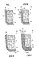
- FIG. 1 is a simplified, partial, cross-sectional view of a vessel in accordance with one embodiment of the present invention
- FIG. 2 is a simplified, partial, enlarged, cross-sectional view of the vessel of FIG. 1 showing a leak point of gas through the vessel wall;
- FIG. 3 is a simplified, partial, cross-sectional view of a vessel in accordance with another embodiment of the present invention.
- FIG. 4 is a simplified, partial, cross-sectional view of a vessel in accordance with yet another embodiment of the present invention.
- a novel system and method for leak detection for non-odorous, flammable and toxic gases are provided in which odorants are not mixed in the bulk gas but are placed in the path of the gas leak.
- the odorants are encapsulated between an appropriate semi-permeable material layer and the walls of the gas storage vessels and piping.
- the term "vessel" is intended to include any vessel, piping, or piping system capable of containing a pressurized gas.
- the properties of the semi-permeable material layer are such that it permits the transport of the stored gases into the encapsulated space where the odorants are placed, but does not permit the transport of the odoriferous substances into the bulk gas or the surrounding atmosphere.
- the odorants may be encapsulated by coating them onto the interior and/or exterior surfaces of the vessels over which a coating ( e.g. , a layer) of a semi-permeable material is placed.
- Odorants also may be encapsulated in between two layers of the semi-permeable materials of similar or different gas transport properties.
- gas leak In the event of a gas leak from a vessel, gas will travel from the bulk storage area within the vessel to the gas leak spot due to the gas pressure gradient. For the leaking gas to travel from the bulk storage area to the leak spot, it must permeate through the semi-permeable material layer and pass through the encapsulated odorants. As the gas passes thought the odorants, the gas carries with it the odorant materials and releases a mixture of the gas and odorant materials from the leak spot. The gas leak, therefore, may be detected by the smell of the odorant. Thus, a gas leak may be detected without contaminating the bulk gas supply.
- the odorant material volatility is such that it has a certain vapor pressure at the storage temperature and it diffuses into the leaking gas to impart to it a detectable amount of the odorant.
- the odorants can be physically carried (entrained) by the high pressure leaking gas to impart a detectable amount of odorant in the gas. Both of these mechanisms may prevail at any given time during the leak of the gas from the vessel.
- the semi-permeable material layer encapsulating the odorant may be coated on the interior surface, the exterior surface, or both the interior and exterior surfaces of the gas storage vessel, the piping and appurtenances.
- the term "appurtenance" is intended to include fittings, valves, meters, and any other devices or objects attached to the vessel and piping which include part of the total gas storage space.
- the encapsulation of the odorant materials in the semi- permeable layer may be accomplished by any of several methods known to those skilled in the art of encapsulation. Several of these methods are given below as examples.
- the application of the odorant encapsulated semi- permeable layer on the interior surface, the exterior surface, or both the interior and exterior surfaces of the gas storage vessel, piping and appurtenances may be done by a variety of methods also given in the examples.
- FIG.1 shows a simplified portion of a cross section of a vessel 10 in accordance with one embodiment of the present invention.
- the vessel 10 has a vessel wall 16 having an inner wall 20 where an odorant layer 14 is located.
- the odorant layer 14 fully covers the entire interior of the vessel 10.
- a semi-permeable material layer 12 is located over the odorant layer 14 on the inner wall of the vessel 10 to fully cover the odorant layer 14.
- the semi-permeable material layer 12 for example, a polymer film, encapsulates the odorant layer 14, which preferably is in the form of a liquid or semi-solid film.
- FIG. 3 illustrates a simplified portion of a cross section of a vessel 30 in accordance with another embodiment of the present invention.
- the vessel 30 has a vessel wall 32 or walls.
- the odorant layer 34 is coated on the outer wall 38 of the vessel wall 32 such that the entire outer surface of the vessel 30 and any appurtenances are completely covered with the odorant layer 34.
- the semi-permeable material layer 36 completely covers the odorant layer 34. Since the gas leaking from vessel wall 32 has to permeate through the odorant layer 34 before the gas reaches the semi-permeable material layer 36, the leaking gas carries with it an appropriate amount (e.g.
- FIG. 4 illustrates a simplified portion of a cross section of a vessel 50 in accordance with another embodiment of the present invention.
- This embodiment combines the benefits of the two embodiments illustrated in Fig. 1 and Fig. 3.
- the vessel 50 has a vessel wall 52 or walls.
- a first odorant layer 54a and a second odorant layer 54b are coated on the inner wall 56 and the outer wall 58 respectively to fully coat the inner wall 56 and the outer wall 58, including any appurtenances.
- a first semi-permeable material layer 60a is located over the first odorant layer 54a and a second semi-permeable material layer 60b is located over the second odorant layer 54b to fully encapsulate the odorant layers (54a, 54b).
- the leaking gas has to permeate through the first semi-permeable material layer 60a, the first odorant layer 54a, the vessel wall 52, and then through the second odorant layer 54b and the second semi-permeable material layer 60b.
- the leaking gas carries with it an appropriate amount (e.g. , about 1-10 mg S/cubic meter gas or more) of the odorant material from the odorant layers (54a, 54b), thus imparting an odor in the leaking gas.
- Example 1 A solution of the odoriferous materials in appropriate solvent is prepared in a concentration of 0.01% to 99.99% w/w.
- the odoriferous materials used are: mercaptans (tetrabutyl mercaptan, isopropyl mercaptan, normal propyl mercaptan, secondary butyl mercaptans, ethyl mercaptans, normal butyl mercaptan, etc.), thiophenes (tetrahydrothiophene), sulfides (dimethyl sulfide, methyl ethyl sulfide), and the like, and combinations thereof, and odorants selected from a group consisting of derivatives of acrylic acid, alkyl ethers of C 4 -C 7 , carboxylic acids, and combinations thereof.
- the solvents used are polar or non-polar or mixtures thereof, depending on the nature of the odorant selected.
- the nature of the solvent is such that it dissolves the odorants, has a relatively high volatility, wets the surfaces over which it is coated and is capable of forming a continuous thin film of liquid or semi-solid odorant solution on the vessel surfaces.
- a thin film of the coating solution is made on the surface of the vessel by contacting the coating solution to the surfaces and drying out the solvents, such that a continuous layer of the odorant is left on the surfaces.
- a single or multiple coating of the odorant solution is done on the surface to create an odorant layer which covers almost all of the desired surface.
- the odorant layer is then subsequently encapsulated by coating over it a single or multiple continuous layer of a semi-permeable or microporous polymeric or non-polymeric material layer which has characteristics such that it permits the transport of the gas through it but does not permit permeation of the odorant.
- the material used to form an encapsulating layer over the odorant film for example, is made using a rubbery polymer such as polydimethyl siloxane amongst other rubbery materials and glassy polymers such as polyimides, polysulfones, polyamides, polyarylates, polyolefins, polycarbonates and the like.
- the encapsulating coating on the vessel surfaces and on the appurtenance surfaces may be accomplished by several methods.
- the art of forming polymeric semi-permeable membranes and microporous membranes is well documented in textbooks, for example, in R.E. Kesting and A.K. Fritzsche, Polymeric Gas Separation Membranes, Wiley (1983) and in R.E. Kesting, Synthetic Polymer Membranes, Wiley (1985).
- the art of making microporous inorganic membranes is well documented, for example, in C.J. Brinker and G.W. Scherer, Sol-Gel Science, Academic Press (1990). In one simple method, the coating solution is filled in the vessel and its appurtenances.
- the coating solution is then drained and the surfaces are dried by volatilization of the solvents, either by natural evaporation or by forced evaporation caused by heating the surfaces, using air or inert gas circulation or the combination thereof.
- the nature of the solvent used in these coatings is such that it does not dissolve the odorant coating that is already on the surface.
- a spray coating method or other methods known to those skilled in the coating art can do the coatings.
- Pre-prepared semi-permeable material layers in the form of membranes may also be placed on the odorant layer to encapsulate the odorant layer. Such semi-permeable membranes can either be commercially purchased or fabricated separately using the known art described, for example, in the references cited herein.
- an over coating is then made by dissolving a rubbery or glassy film forming polymer in an appropriate volatile solvent at a concentration ranging from 0.1 % to 10% w/w/ solution depending on the thickness of the coating needed.
- the nature of the solvent used for these coatings is such that it does not dissolve the odorant coating that is already on the surface.
- Single layer or multiple coatings are made to assure that the odorant layer is fully encapsulated between the surface of the vessel and the coating polymer.
- Example 2 The odoriferous material in Example 1 is mixed with an appropriate polymer to make a coating solution capable of forming a film on the surface of the vessel and its appurtenances.
- a 0.01 - 10 % w/w solution of a water soluble polymer coating material from the family of polyacrylic acid, polyvinyl acetate, poly vinyl alcohols, etc. is mixed with 0.01-100% w/w of the odoriferous materials solution to form the odoriferous coating solution.
- a single layer or multi-layer coating of this material is applied to the walls of the gas vessel.
- the odorant / polymer coating is then encapsulated by making an additional layer of rubbery or glassy polymers over it as described in Example 1.
- Example 3 The first coating of the odoriferous material in Example 1 is made in an appropriate polymer coating material that is capable of forming a film on the surface of the vessel and accessories.
- a 0.01 - 10 % w/w solution of a non-aqueous solvent coating material from the family of polydimethyl siloxanes, polyphasphazenes, and the like, is mixed with 0.01-100% w/w of the odoriferous materials and the appropriate surfaces are coated with them.
- a single layer or multi-layer coating of this material is applied to the walls of the gas vessel.
- the odorant/polymer coating is then encapsulated by making an additional layer of rubbery or glassy polymers as taught in Example 1.
- Example 4 The coating described in Example 3 is cross linked by using cross linking agents in the coating solution and/or using external means, e.g. , heat, irradiation, and the like, to cross link the coating.
- a cross linked coating may be structurally stronger and less prone to the attack of the solvents than a non-cross linked coating.
- the art of making coatings of the rubbery materials and their cross-linking is taught by J.H. Henis and M.K. Tripodi in U.S. Patent No. 4,230,463 and described in a paper published in the Journal of Membrane Science, 8, 233 (1981).
- Example 5 The coating described in Example 4 is encapsulated in a polymer layer as given in Example 1 but is cross linked using similar cross linking methods as used in Example 4.
- Example 6 The coatings in Examples 1 to 5 are a mix of individual polymer layers of cross linked and uncross linked polymers in several possible manners.
- Example 7 The coatings made in Examples 1 to 6 where the initial layer (in contact with the vessel or appurtenances surfaces) and the final layer (in contact with the gas, when the vessel is filled) coatings do not contain odorant materials. The odorant is sandwiched between the two coating layers. These coatings are made in a similar manner as described in Example 1.
- Example 8 The coatings in Example 7 are made using a glassy polymer such as polysulfone, polyamide, polyimide, polyarylate and other appropriate polymers.
- a glassy polymer such as polysulfone, polyamide, polyimide, polyarylate and other appropriate polymers.
- Example 9 The coating in Examples 1 to 7 are made using glassy polymers with an overlay of the rubbery polymer or a rubbery polymer with an overlay of glassy polymers, in any combination, depending on the number of total layers desired.
- Example 10 to Example 14 A glassy polymer solution is made in an appropriate solvent (Example 10), solvent mixture (Example 11), solvent / nonsolvent mixture (Example 12), solvent/poreformer mixer (Example 13) or solvent / nonsolvent / poreformer mixer (Example 14) in a polymer concentration from 0.5% to 50% polymer depending on the nature of the polymer, solvent, nonsolvent and poreformer used in a given solution.
- the solution is coated in the vessel and the appurtenances as in Example 1 and the solvent is evaporated. The resulting coating may have a microporous network.
- the coating is dried and the pores are filled with a 0.01-100 % w/w solution of the odorant by contacting that solution with the microporous coating.
- the odorant material is drawn in the pores either by sorption or by capillary suction.
- the odorant material is sorbed in the microporous coating by sorption of the vapors of the odorant material.
- the coating is encapsulated by making a semi- permeable coating on top of it as in Example 1.
- Example 15 In the coating solution in Examples 10-14, 0.01 - 50 % of the odorant material in relation to the weight of the coating polymer is added to the coating solution.
- the resulting microporous coatings contain the odorants in its bulk.
- the coating is encapsulated by making a semi-permeable coating on top of it as in Example 1.
- Example 20 to Example 24 A dense coating is laid on the vessel surface prior to laying a microporous coating as in Examples 10-14. This is accomplished by making a 0.01 - 50 % solution of a glassy or rubbery polymer in an appropriate solvent or solvent mixture and contacting with the appropriate surfaces and evaporating the solvents to leave a thin dense polymer film on the said surfaces. The coatings discussed in Examples 15 to 19 are then formed over it.
- Example 25 to Example 29 in addition to a dense coating on the vessel surface, an additional dense coating is laid on the surface exposed to the gas as well. This is done by making a 0.01 - 50 % solution of a glassy or rubbery polymer in an appropriate solvent or solvent mixture and contacting with the appropriate surfaces and evaporating the solvents to leave a thin dense polymer film on the said surfaces.
- Example 30 A glassy polymer, such as polysulfone, polyimide, polyetherketone, polycarbonate, polyamide, polyarylate, etc., is made in a 0.01- 50 % w/w solution in a solvent, solvent mixture or solvent mixture containing pore formers at appropriate concentrations and is coated on the vessel surfaces.
- the coating is then coagulated in an appropriate coagulant solution, preferably water or water containing minor amounts of solvents, non-solvents or surfactants.
- the coagulation is done at a temperature from 1 degree Celsius to 80 degrees Celsius depending on the nature of the pore structure desired for the coating.
- the coating is either dried by use of heat and forced convection or goes through a solvent exchange in order to minimize the pore collapse.
- the dried coating is then exposed with the odoriferous materials either in their solution or in the vapors formed to impregnate the dried coating with the odiferous materials.
- Example 31 In Example 30, an additional dense layer is placed on top of the asymmetric coating containing the odorant materials formed as in Example 1.
- Example 32 A dense layer of polymer is laid on the surface of the vessel prior to laying the asymmetric film of Example 31.
- Example 33 to Examples 64 Coatings performed in Examples 1 to 32 are done on the exterior surface of the gas storage vessel and the appurtenances.
- Examples 65 to 96 Coatings are performed on the surfaces of the gas storage vessel and appurtenances on both sides of the vessel, surfaces exposed to the gas as in Examples 1 to 31, and on the surfaces away from the gas as in Examples 33 to 64.
- the liquid odorants can be immobilized on the solid sorbents such as clays, zeolites, cellulosic materials (e.g. , saw dust), polymer powder, and the like.
- a solution of 0.01 - 100% w/w of the odorant in an appropriate aqueous or nonaqueous solvent is mixed with the sorbents and the solvent is removed by volitilization by heat or forced by air or inert gas circulation.
- the immobilized odorant is used in Examples 1 to 96 for the formation of the encapsulated odorant coatings.
Landscapes
- Physics & Mathematics (AREA)
- General Physics & Mathematics (AREA)
- Examining Or Testing Airtightness (AREA)
- Emergency Alarm Devices (AREA)
Applications Claiming Priority (2)
| Application Number | Priority Date | Filing Date | Title |
|---|---|---|---|
| US321311 | 2002-12-16 | ||
| US10/321,311 US7229831B2 (en) | 2002-12-16 | 2002-12-16 | Leak site odorization for gas leak detection |
Publications (2)
| Publication Number | Publication Date |
|---|---|
| EP1431736A2 true EP1431736A2 (fr) | 2004-06-23 |
| EP1431736A3 EP1431736A3 (fr) | 2006-01-18 |
Family
ID=32393001
Family Applications (1)
| Application Number | Title | Priority Date | Filing Date |
|---|---|---|---|
| EP03028745A Withdrawn EP1431736A3 (fr) | 2002-12-16 | 2003-12-12 | Odorisation d'un lieu de fuite pour la détection d'une fuite de gaz |
Country Status (3)
| Country | Link |
|---|---|
| US (1) | US7229831B2 (fr) |
| EP (1) | EP1431736A3 (fr) |
| CA (1) | CA2452465C (fr) |
Families Citing this family (22)
| Publication number | Priority date | Publication date | Assignee | Title |
|---|---|---|---|---|
| US20040115818A1 (en) * | 2002-12-16 | 2004-06-17 | Puri Pushpinder Singh | Leak detection by reactions at the leak site |
| US7915047B2 (en) | 2007-11-19 | 2011-03-29 | Los Alamos National Security, Llc | Coating for leak detection and method |
| US8206854B2 (en) | 2008-05-21 | 2012-06-26 | Enersol Inc., N.A.L.P. | Hydrogen odorization |
| AU2010336001B2 (en) * | 2009-12-21 | 2014-11-06 | Shreepad Krishna Bhat | Leak detection device |
| FR2965556B1 (fr) * | 2010-09-30 | 2013-08-02 | Sartorius Stedim Biotech Sa | Detection de l'integrite d'une poche souple, fermee, etanche, en matiere plastique, destinee a recevoir et proteger un produit ou un dispositif biopharmaceutique |
| US8529846B1 (en) * | 2011-10-26 | 2013-09-10 | The United States of America as Represented by the Department of Navy | Composite health monitoring/damage mitigation using multi-component microcapsules |
| DE102017203607A1 (de) | 2017-03-06 | 2018-09-06 | Bayerische Motoren Werke Aktiengesellschaft | Wasserstoffführendes Bauteil, Brennstoffzellensystem und Kraftfahrzeug |
| US12017506B2 (en) | 2020-08-20 | 2024-06-25 | Denso International America, Inc. | Passenger cabin air control systems and methods |
| US11881093B2 (en) | 2020-08-20 | 2024-01-23 | Denso International America, Inc. | Systems and methods for identifying smoking in vehicles |
| US11760169B2 (en) | 2020-08-20 | 2023-09-19 | Denso International America, Inc. | Particulate control systems and methods for olfaction sensors |
| US11828210B2 (en) | 2020-08-20 | 2023-11-28 | Denso International America, Inc. | Diagnostic systems and methods of vehicles using olfaction |
| US11932080B2 (en) | 2020-08-20 | 2024-03-19 | Denso International America, Inc. | Diagnostic and recirculation control systems and methods |
| US12377711B2 (en) | 2020-08-20 | 2025-08-05 | Denso International America, Inc. | Vehicle feature control systems and methods based on smoking |
| US11636870B2 (en) | 2020-08-20 | 2023-04-25 | Denso International America, Inc. | Smoking cessation systems and methods |
| US11813926B2 (en) | 2020-08-20 | 2023-11-14 | Denso International America, Inc. | Binding agent and olfaction sensor |
| US11760170B2 (en) | 2020-08-20 | 2023-09-19 | Denso International America, Inc. | Olfaction sensor preservation systems and methods |
| US12269315B2 (en) | 2020-08-20 | 2025-04-08 | Denso International America, Inc. | Systems and methods for measuring and managing odor brought into rental vehicles |
| US12251991B2 (en) | 2020-08-20 | 2025-03-18 | Denso International America, Inc. | Humidity control for olfaction sensors |
| CN112630092B (zh) * | 2020-12-15 | 2023-12-19 | 阜阳科优检测科技有限公司 | 一种基于半透膜的土壤污染原位检测装置 |
| US11712672B1 (en) | 2022-05-03 | 2023-08-01 | GPL Odorizers LLC | Accurate odorization control |
| US12290791B2 (en) | 2022-05-03 | 2025-05-06 | GPL Odorizers LLC | Accurate odorization control |
| CN116571899B (zh) * | 2023-04-12 | 2025-08-12 | 合肥工业大学 | 采用飞秒激光在钨箔上打孔并与pdms结合制备高压漏孔的方法 |
Family Cites Families (8)
| Publication number | Priority date | Publication date | Assignee | Title |
|---|---|---|---|---|
| US3003349A (en) * | 1959-03-09 | 1961-10-10 | Little Inc A | Warning system |
| US3140156A (en) * | 1960-06-09 | 1964-07-07 | Auergesellschaft Gmbh | Canister with olfactory warner |
| US3634053A (en) * | 1970-04-06 | 1972-01-11 | Inst Gas Technology | Odorization method and apparatus |
| JPH0335138A (ja) * | 1989-06-30 | 1991-02-15 | Hochiki Corp | 配管部材の水素漏れ検知構造 |
| US5335373A (en) * | 1991-11-29 | 1994-08-09 | Dresdner Jr Karl P | Protective medical gloves and methods for their use |
| US5695089A (en) * | 1995-01-27 | 1997-12-09 | Steel Tank Institute | Lightweight double wall storage tank |
| US6063632A (en) * | 1998-11-12 | 2000-05-16 | Perkins; Gary | Water leak detection |
| US20040084083A1 (en) * | 2002-07-15 | 2004-05-06 | Ballard Power Systems Inc. | Distribution of non-odorized gas |
-
2002
- 2002-12-16 US US10/321,311 patent/US7229831B2/en not_active Expired - Fee Related
-
2003
- 2003-12-09 CA CA002452465A patent/CA2452465C/fr not_active Expired - Fee Related
- 2003-12-12 EP EP03028745A patent/EP1431736A3/fr not_active Withdrawn
Also Published As
| Publication number | Publication date |
|---|---|
| US7229831B2 (en) | 2007-06-12 |
| EP1431736A3 (fr) | 2006-01-18 |
| US20040115819A1 (en) | 2004-06-17 |
| CA2452465A1 (fr) | 2004-06-16 |
| CA2452465C (fr) | 2009-01-06 |
Similar Documents
| Publication | Publication Date | Title |
|---|---|---|
| CA2452465C (fr) | Detection des fuites de gaz par odorisation de l'emplacement | |
| CA2452463C (fr) | Detection d'une fuite par reactions a son emplacement | |
| US7192459B2 (en) | Addition of odorants to gases for leak detection | |
| EP1434044A2 (fr) | Réservoirs à double parois pour odorants | |
| US7024869B2 (en) | Addition of odorants to hydrogen by incorporating odorants with hydrogen storage materials | |
| JP5444348B2 (ja) | 石油製品の貯蔵・輸送装置 | |
| CA2816688C (fr) | Dispositif de separation de gaz, reacteur a membrane et dispositif de production d'hydrogene | |
| RU2673837C2 (ru) | Способ и система для инертирования стенки резервуара для хранения сжиженного топливного газа | |
| US5809650A (en) | Lightweight double wall storge tank | |
| KR970700518A (ko) | 개선된 분산제 방출 시스템 및 이의 제조 방법과 사용 방법(improved dispersant delivery system and method for producing and using same) | |
| FR3018278A1 (fr) | Traitement de diffusion forcee d'une piece isolante en mousse synthetique expansee | |
| US6820464B2 (en) | Odorized seals for the detection of gas leak | |
| Park et al. | Preparation of water‐swollen hydrogel membranes for gas separation | |
| CA2452462A1 (fr) | Recipients a parois doubles pour gaz odorisants | |
| CA2927696C (fr) | Tuyau ou tube servant a collecter et a transporter un echantillon de gaz | |
| Compañ et al. | On the crystallinity effect on the gas sorption in semicrystalline linear low density polyethylene (LLDPE) | |
| WO2018015640A1 (fr) | Module et systeme de depressurisation d'un reservoir cryogenique. | |
| TW202407251A (zh) | 儲存及/或運輸液化氣體之設備 | |
| JP2003166699A (ja) | 気体格納装置、気体供給装置、気体の搬送方法及び気体格納装置の取扱い方法 | |
| Aftaniuk et al. | Analysis of Inert Gas Systems of Modern Chemical Tankers | |
| CA2196941A1 (fr) | Contenant double | |
| RU2211062C1 (ru) | Способ предупреждения взрывов и экологической защиты резервуаров с нефтепродуктами | |
| Esfandiari et al. | New Insight Into Odor Fading in Natural Gas Distribution Networks: Recent Breakthroughs and Challenges | |
| CA2141357C (fr) | Cuve de stockage legere a double paroi | |
| JP2009185827A (ja) | ガス輸送・貯蔵用タンク |
Legal Events
| Date | Code | Title | Description |
|---|---|---|---|
| PUAI | Public reference made under article 153(3) epc to a published international application that has entered the european phase |
Free format text: ORIGINAL CODE: 0009012 |
|
| AK | Designated contracting states |
Kind code of ref document: A2 Designated state(s): AT BE BG CH CY CZ DE DK EE ES FI FR GB GR HU IE IT LI LU MC NL PT RO SE SI SK TR |
|
| AX | Request for extension of the european patent |
Extension state: AL LT LV MK |
|
| PUAL | Search report despatched |
Free format text: ORIGINAL CODE: 0009013 |
|
| AK | Designated contracting states |
Kind code of ref document: A3 Designated state(s): AT BE BG CH CY CZ DE DK EE ES FI FR GB GR HU IE IT LI LU MC NL PT RO SE SI SK TR |
|
| AX | Request for extension of the european patent |
Extension state: AL LT LV MK |
|
| 17P | Request for examination filed |
Effective date: 20060220 |
|
| AKX | Designation fees paid |
Designated state(s): AT BE BG CH CY CZ DE DK EE ES FI FR GB GR HU IE IT LI LU MC NL PT RO SE SI SK TR |
|
| STAA | Information on the status of an ep patent application or granted ep patent |
Free format text: STATUS: THE APPLICATION IS DEEMED TO BE WITHDRAWN |
|
| 18D | Application deemed to be withdrawn |
Effective date: 20100701 |