EP1431738A2 - Zusatz von Gerauchstoffen zu Gasen zur Leckerfassung - Google Patents
Zusatz von Gerauchstoffen zu Gasen zur Leckerfassung Download PDFInfo
- Publication number
- EP1431738A2 EP1431738A2 EP03028748A EP03028748A EP1431738A2 EP 1431738 A2 EP1431738 A2 EP 1431738A2 EP 03028748 A EP03028748 A EP 03028748A EP 03028748 A EP03028748 A EP 03028748A EP 1431738 A2 EP1431738 A2 EP 1431738A2
- Authority
- EP
- European Patent Office
- Prior art keywords
- odorant
- interior volume
- vessel
- gas
- conduit
- Prior art date
- Legal status (The legal status is an assumption and is not a legal conclusion. Google has not performed a legal analysis and makes no representation as to the accuracy of the status listed.)
- Withdrawn
Links
- 239000003205 fragrance Substances 0.000 title claims abstract description 218
- 239000007789 gas Substances 0.000 title claims description 135
- 238000001514 detection method Methods 0.000 title description 10
- 239000000463 material Substances 0.000 claims abstract description 143
- 239000012530 fluid Substances 0.000 claims abstract description 26
- 238000000034 method Methods 0.000 claims description 38
- 239000000203 mixture Substances 0.000 claims description 22
- QMMFVYPAHWMCMS-UHFFFAOYSA-N Dimethyl sulfide Chemical compound CSC QMMFVYPAHWMCMS-UHFFFAOYSA-N 0.000 claims description 18
- WQAQPCDUOCURKW-UHFFFAOYSA-N butanethiol Chemical group CCCCS WQAQPCDUOCURKW-UHFFFAOYSA-N 0.000 claims description 18
- 230000008786 sensory perception of smell Effects 0.000 claims description 17
- 229910052739 hydrogen Inorganic materials 0.000 claims description 16
- UFHFLCQGNIYNRP-UHFFFAOYSA-N Hydrogen Chemical compound [H][H] UFHFLCQGNIYNRP-UHFFFAOYSA-N 0.000 claims description 15
- 239000001257 hydrogen Substances 0.000 claims description 15
- 229920000642 polymer Polymers 0.000 claims description 15
- SUVIGLJNEAMWEG-UHFFFAOYSA-N propane-1-thiol Chemical compound CCCS SUVIGLJNEAMWEG-UHFFFAOYSA-N 0.000 claims description 12
- KJRCEJOSASVSRA-UHFFFAOYSA-N propane-2-thiol Chemical compound CC(C)S KJRCEJOSASVSRA-UHFFFAOYSA-N 0.000 claims description 12
- 229920001971 elastomer Polymers 0.000 claims description 9
- RWSOTUBLDIXVET-UHFFFAOYSA-N Dihydrogen sulfide Chemical class S RWSOTUBLDIXVET-UHFFFAOYSA-N 0.000 claims description 8
- LSDPWZHWYPCBBB-UHFFFAOYSA-N Methanethiol Chemical compound SC LSDPWZHWYPCBBB-UHFFFAOYSA-N 0.000 claims description 6
- XYWDPYKBIRQXQS-UHFFFAOYSA-N di-isopropyl sulphide Natural products CC(C)SC(C)C XYWDPYKBIRQXQS-UHFFFAOYSA-N 0.000 claims description 6
- DNJIEGIFACGWOD-UHFFFAOYSA-N ethanethiol Chemical group CCS DNJIEGIFACGWOD-UHFFFAOYSA-N 0.000 claims description 6
- WXEHBUMAEPOYKP-UHFFFAOYSA-N methylsulfanylethane Chemical compound CCSC WXEHBUMAEPOYKP-UHFFFAOYSA-N 0.000 claims description 6
- 239000012466 permeate Substances 0.000 claims description 6
- RAOIDOHSFRTOEL-UHFFFAOYSA-N tetrahydrothiophene Chemical compound C1CCSC1 RAOIDOHSFRTOEL-UHFFFAOYSA-N 0.000 claims description 6
- 150000003568 thioethers Chemical class 0.000 claims description 6
- 229930192474 thiophene Natural products 0.000 claims description 6
- 150000003577 thiophenes Chemical class 0.000 claims description 6
- NIXOWILDQLNWCW-UHFFFAOYSA-N Acrylic acid Chemical class OC(=O)C=C NIXOWILDQLNWCW-UHFFFAOYSA-N 0.000 claims description 5
- 239000004952 Polyamide Substances 0.000 claims description 5
- 239000004642 Polyimide Substances 0.000 claims description 5
- 150000005215 alkyl ethers Chemical class 0.000 claims description 5
- 150000001735 carboxylic acids Chemical class 0.000 claims description 5
- 235000013870 dimethyl polysiloxane Nutrition 0.000 claims description 5
- 229920000435 poly(dimethylsiloxane) Polymers 0.000 claims description 5
- 229920001643 poly(ether ketone) Polymers 0.000 claims description 5
- 229920002492 poly(sulfone) Polymers 0.000 claims description 5
- 229920002647 polyamide Polymers 0.000 claims description 5
- 229920001230 polyarylate Polymers 0.000 claims description 5
- 229920001721 polyimide Polymers 0.000 claims description 5
- 229920000098 polyolefin Polymers 0.000 claims description 5
- 239000000758 substrate Substances 0.000 claims description 5
- 239000004417 polycarbonate Substances 0.000 claims description 4
- 229920000515 polycarbonate Polymers 0.000 claims description 4
- VNWKTOKETHGBQD-UHFFFAOYSA-N methane Chemical compound C VNWKTOKETHGBQD-UHFFFAOYSA-N 0.000 description 22
- 235000019645 odor Nutrition 0.000 description 17
- 239000010410 layer Substances 0.000 description 14
- 239000003345 natural gas Substances 0.000 description 9
- 241000282414 Homo sapiens Species 0.000 description 8
- 238000000576 coating method Methods 0.000 description 8
- 239000012528 membrane Substances 0.000 description 8
- 239000000243 solution Substances 0.000 description 8
- 239000007788 liquid Substances 0.000 description 7
- 239000011248 coating agent Substances 0.000 description 6
- 239000000446 fuel Substances 0.000 description 6
- 239000012229 microporous material Substances 0.000 description 6
- 239000002904 solvent Substances 0.000 description 5
- ATUOYWHBWRKTHZ-UHFFFAOYSA-N Propane Chemical compound CCC ATUOYWHBWRKTHZ-UHFFFAOYSA-N 0.000 description 4
- 239000002775 capsule Substances 0.000 description 4
- -1 perfluoro Chemical group 0.000 description 4
- 239000003208 petroleum Substances 0.000 description 4
- 238000001179 sorption measurement Methods 0.000 description 4
- 239000004215 Carbon black (E152) Substances 0.000 description 3
- NINIDFKCEFEMDL-UHFFFAOYSA-N Sulfur Chemical compound [S] NINIDFKCEFEMDL-UHFFFAOYSA-N 0.000 description 3
- 230000001419 dependent effect Effects 0.000 description 3
- 238000013461 design Methods 0.000 description 3
- 238000009792 diffusion process Methods 0.000 description 3
- 238000005538 encapsulation Methods 0.000 description 3
- 238000001704 evaporation Methods 0.000 description 3
- 230000008020 evaporation Effects 0.000 description 3
- 229930195733 hydrocarbon Natural products 0.000 description 3
- 150000002430 hydrocarbons Chemical class 0.000 description 3
- 238000002347 injection Methods 0.000 description 3
- 239000007924 injection Substances 0.000 description 3
- 239000002184 metal Substances 0.000 description 3
- 229910052751 metal Inorganic materials 0.000 description 3
- 239000002594 sorbent Substances 0.000 description 3
- 229910052717 sulfur Inorganic materials 0.000 description 3
- 239000011593 sulfur Substances 0.000 description 3
- 238000012546 transfer Methods 0.000 description 3
- IJGRMHOSHXDMSA-UHFFFAOYSA-N Atomic nitrogen Chemical compound N#N IJGRMHOSHXDMSA-UHFFFAOYSA-N 0.000 description 2
- 239000003463 adsorbent Substances 0.000 description 2
- 230000004888 barrier function Effects 0.000 description 2
- 230000008901 benefit Effects 0.000 description 2
- 238000009835 boiling Methods 0.000 description 2
- 239000000919 ceramic Substances 0.000 description 2
- 238000002485 combustion reaction Methods 0.000 description 2
- 238000009833 condensation Methods 0.000 description 2
- 230000005494 condensation Effects 0.000 description 2
- 238000009826 distribution Methods 0.000 description 2
- 239000010408 film Substances 0.000 description 2
- 150000002431 hydrogen Chemical class 0.000 description 2
- 230000009965 odorless effect Effects 0.000 description 2
- 239000003209 petroleum derivative Substances 0.000 description 2
- 239000004033 plastic Substances 0.000 description 2
- 239000001294 propane Substances 0.000 description 2
- 238000012552 review Methods 0.000 description 2
- 239000007787 solid Substances 0.000 description 2
- 239000000126 substance Substances 0.000 description 2
- UGFAIRIUMAVXCW-UHFFFAOYSA-N Carbon monoxide Chemical compound [O+]#[C-] UGFAIRIUMAVXCW-UHFFFAOYSA-N 0.000 description 1
- IAYPIBMASNFSPL-UHFFFAOYSA-N Ethylene oxide Chemical compound C1CO1 IAYPIBMASNFSPL-UHFFFAOYSA-N 0.000 description 1
- 239000000654 additive Substances 0.000 description 1
- 239000003125 aqueous solvent Substances 0.000 description 1
- 229910002091 carbon monoxide Inorganic materials 0.000 description 1
- 238000006243 chemical reaction Methods 0.000 description 1
- 239000003795 chemical substances by application Substances 0.000 description 1
- 150000001875 compounds Chemical class 0.000 description 1
- 230000007547 defect Effects 0.000 description 1
- 238000011161 development Methods 0.000 description 1
- 239000004205 dimethyl polysiloxane Substances 0.000 description 1
- 238000001035 drying Methods 0.000 description 1
- 238000005516 engineering process Methods 0.000 description 1
- 239000011152 fibreglass Substances 0.000 description 1
- 238000007710 freezing Methods 0.000 description 1
- 230000008014 freezing Effects 0.000 description 1
- 239000002737 fuel gas Substances 0.000 description 1
- 239000011521 glass Substances 0.000 description 1
- 230000005484 gravity Effects 0.000 description 1
- 238000010438 heat treatment Methods 0.000 description 1
- 239000011261 inert gas Substances 0.000 description 1
- 230000007257 malfunction Effects 0.000 description 1
- 230000000873 masking effect Effects 0.000 description 1
- 238000002156 mixing Methods 0.000 description 1
- 238000012986 modification Methods 0.000 description 1
- 230000004048 modification Effects 0.000 description 1
- QKCGXXHCELUCKW-UHFFFAOYSA-N n-[4-[4-(dinaphthalen-2-ylamino)phenyl]phenyl]-n-naphthalen-2-ylnaphthalen-2-amine Chemical compound C1=CC=CC2=CC(N(C=3C=CC(=CC=3)C=3C=CC(=CC=3)N(C=3C=C4C=CC=CC4=CC=3)C=3C=C4C=CC=CC4=CC=3)C3=CC4=CC=CC=C4C=C3)=CC=C21 QKCGXXHCELUCKW-UHFFFAOYSA-N 0.000 description 1
- 229910052757 nitrogen Inorganic materials 0.000 description 1
- 239000012454 non-polar solvent Substances 0.000 description 1
- 239000002798 polar solvent Substances 0.000 description 1
- 238000010248 power generation Methods 0.000 description 1
- 230000008569 process Effects 0.000 description 1
- 230000001902 propagating effect Effects 0.000 description 1
- 230000001105 regulatory effect Effects 0.000 description 1
- 239000002990 reinforced plastic Substances 0.000 description 1
- 238000011160 research Methods 0.000 description 1
- 238000005201 scrubbing Methods 0.000 description 1
- 238000007789 sealing Methods 0.000 description 1
- 238000000926 separation method Methods 0.000 description 1
- 239000002356 single layer Substances 0.000 description 1
- 239000011877 solvent mixture Substances 0.000 description 1
- 238000005507 spraying Methods 0.000 description 1
- 150000003464 sulfur compounds Chemical class 0.000 description 1
- 229920001059 synthetic polymer Polymers 0.000 description 1
- TXEYQDLBPFQVAA-UHFFFAOYSA-N tetrafluoromethane Chemical compound FC(F)(F)F TXEYQDLBPFQVAA-UHFFFAOYSA-N 0.000 description 1
- 239000010409 thin film Substances 0.000 description 1
- 231100000331 toxic Toxicity 0.000 description 1
- 230000002588 toxic effect Effects 0.000 description 1
- 238000009827 uniform distribution Methods 0.000 description 1
- XLYOFNOQVPJJNP-UHFFFAOYSA-N water Substances O XLYOFNOQVPJJNP-UHFFFAOYSA-N 0.000 description 1
- 238000009736 wetting Methods 0.000 description 1
Images

Classifications
-
- G—PHYSICS
- G01—MEASURING; TESTING
- G01M—TESTING STATIC OR DYNAMIC BALANCE OF MACHINES OR STRUCTURES; TESTING OF STRUCTURES OR APPARATUS, NOT OTHERWISE PROVIDED FOR
- G01M3/00—Investigating fluid-tightness of structures
- G01M3/02—Investigating fluid-tightness of structures by using fluid or vacuum
- G01M3/04—Investigating fluid-tightness of structures by using fluid or vacuum by detecting the presence of fluid at the leakage point
- G01M3/20—Investigating fluid-tightness of structures by using fluid or vacuum by detecting the presence of fluid at the leakage point using special tracer materials, e.g. dye, fluorescent material, radioactive material
- G01M3/22—Investigating fluid-tightness of structures by using fluid or vacuum by detecting the presence of fluid at the leakage point using special tracer materials, e.g. dye, fluorescent material, radioactive material for pipes, cables or tubes; for pipe joints or seals; for valves; for welds; for containers, e.g. radiators
- G01M3/226—Investigating fluid-tightness of structures by using fluid or vacuum by detecting the presence of fluid at the leakage point using special tracer materials, e.g. dye, fluorescent material, radioactive material for pipes, cables or tubes; for pipe joints or seals; for valves; for welds; for containers, e.g. radiators for containers, e.g. radiators
-
- Y—GENERAL TAGGING OF NEW TECHNOLOGICAL DEVELOPMENTS; GENERAL TAGGING OF CROSS-SECTIONAL TECHNOLOGIES SPANNING OVER SEVERAL SECTIONS OF THE IPC; TECHNICAL SUBJECTS COVERED BY FORMER USPC CROSS-REFERENCE ART COLLECTIONS [XRACs] AND DIGESTS
- Y02—TECHNOLOGIES OR APPLICATIONS FOR MITIGATION OR ADAPTATION AGAINST CLIMATE CHANGE
- Y02E—REDUCTION OF GREENHOUSE GAS [GHG] EMISSIONS, RELATED TO ENERGY GENERATION, TRANSMISSION OR DISTRIBUTION
- Y02E60/00—Enabling technologies; Technologies with a potential or indirect contribution to GHG emissions mitigation
- Y02E60/30—Hydrogen technology
- Y02E60/32—Hydrogen storage
-
- Y—GENERAL TAGGING OF NEW TECHNOLOGICAL DEVELOPMENTS; GENERAL TAGGING OF CROSS-SECTIONAL TECHNOLOGIES SPANNING OVER SEVERAL SECTIONS OF THE IPC; TECHNICAL SUBJECTS COVERED BY FORMER USPC CROSS-REFERENCE ART COLLECTIONS [XRACs] AND DIGESTS
- Y10—TECHNICAL SUBJECTS COVERED BY FORMER USPC
- Y10T—TECHNICAL SUBJECTS COVERED BY FORMER US CLASSIFICATION
- Y10T436/00—Chemistry: analytical and immunological testing
- Y10T436/22—Hydrogen, per se
Definitions
- the present invention relates to fluid leak detection, and in particular to the leak detection of gases by odor generated by adding odiferous materials to the gases.
- hydrogen gas is emerging as a leading candidate for the fuel of choice.
- hydrogen may be obtained from an abundant, renewable, resource, water.
- Odorization of gases for leak detection is well known in the natural gas and petroleum gas industries.
- a paper by M.J. Usher Proc. Int. Scho. Hydrocarbon Meas. 73 rd , pages 743-48 (1998)) reviews the history, application, compounds, and safety practices in selecting and applying odorants in the natural gas industry. Mixing small quantities of odorants with gases is a substantially universal practice in natural and petroleum gases.
- a paper by I. Katuran Proc. Int. Sch. Hydrocarbon Meas., 64 th , pages 325-30 (1989) reports on natural gas odorants, their safety and handling precautions, handling techniques, and methods of adding odorants to gases.
- Natural gas for public gas supplies typically contains 5-10 mg of sulfur per cubic meter of gas.
- gases included in this category are, for example, nitrogen, carbon monoxide, nitrogen trifluoride, ethylene oxide, carbon tetrafluoride and other perfluoro gases.
- odorant agents are sulfur compounds, e . g ., mercaptans (tetrabutyl mercaptan, isopropyl mercaptan, normal propyl mercaptan, secondary butyl mercaptans, ethyl mercaptans, normal butyl mercaptan, etc.), thiophenes (tetrahydrothiophene), sulfides (dimethyl sulfide, methyl ethyl sulfide), etc.
- the chemicals used are also expected to have certain other attributes, such as low vapor pressure (high boiling point), low freezing point, low specific gravity so that they are fully dispersed in the gas, and appropriate thermal properties (e.g. , they will not freeze at appropriate temperatures and will not cause over odorization in the hot weather).
- the general quality requirements, as specified for sulfur containing odorants in ISO/DIS 13734, are: (1) a cloud point of less than -30 degrees Celsius, (2) a boiling point of less than 130 degrees Celsius, and (3) evaporation residue of less than 0.2 %.
- odorants further will likely include an odorant concentration high enough to allow detection with a fuel gas concentration of 1/5 the lean limit of combustion. These requirements exist for natural gas (SAE J 1616, NFPA 52-1992) and petroleum gas (NFPA 58-1989).
- a traditional method of using odorants is to meter a predetermined amount of the odorant into the gas stream either continuously in the pipeline or on a batch basis in the storage tanks.
- Electronic odorant injection systems (refer Zeck, DO53017A) have been designed that inject a prescribed amount of the odorants into the gas stream proportional to its flow rate.
- An electronic odorant injection system has five duties that it must perform to provide a safe source of natural gas. Combined, these duties insure that enough odorant is injected to make the gas properly detectable to human beings. These duties include:
- the typical full-featured electronic delivery odorant system should incorporate the following major components:
- Dispensing of the odorant may be done either in the gas tank or in the gas delivery pipes. Since the odorants may be added to the bulk gas in a tank, their concentration varies throughout the tank. The odorant concentration in the delivered gas also is dependent on the speed at which the gas is dispensed. At low dispensing speeds, odorants get adsorbed on the delivery pipe walls, resulting in a low odorant concentration in the bulk gas.
- the present invention is an apparatus and a method for dispensing an odorant to a fluid in a vessel having an interior volume containing the fluid.
- the fluid is a pressurized gas.
- a first embodiment is an apparatus for dispensing an odorant to a fluid in a vessel having an interior volume containing the fluid.
- the apparatus includes at least one odorant material disposed in the interior volume and an odorant-permeable material encapsulating the odorant material, which has at least one detectable odor.
- the odorant-permeable material is permeated by at least a portion of the odorant material, whereby an equilibrium composition and an equilibrium concentration of the odorant material are maintained in the interior volume of the vessel.
- the detectable odor is detectable by a sense of smell of a living being.
- the fluid is hydrogen.
- At least a portion of the fluid is a gas stored and/or transported in the vessel.
- at least a portion of the gas is at or above an ambient pressure.
- At least a portion of the odorant material is selected from a group consisting of mercaptans (tetrabutyl mercaptan, isopropyl mercaptan, normal propyl mercaptan, secondary butyl mercaptans, ethyl mercaptans, normal butyl mercaptan), thiophenes (tetrahydrothiophene), sulfides (dimethyl sulfide, methyl ethyl sulfide), and combinations thereof, and odorants selected from a group consisting of derivatives of acrylic acid, alkyl ethers of C 4 -C 7 , carboxylic acids, and combinations thereof.
- mercaptans tetrabutyl mercaptan, isopropyl mercaptan, normal propyl mercaptan, secondary butyl mercaptans, ethyl mercaptans, normal butyl mercaptan
- the odorant-permeable material is a polymer selected from a group consisting of a rubbery polymer, a glassy polymer, and combinations thereof, the rubbery polymer being selected from a group consisting of polydimethyl siloxanes, poly phasphazenes, and combinations thereof, and the glassy polymer being selected from a group consisting of polyimides, polysulfones, polyamides, polyarylates, polyolefins, polyetherketones, polycarbonates, and combinations thereof.
- Another embodiment of the apparatus is similar to the first embodiment but includes a conduit disposed in the interior volume of the vessel.
- the conduit is adapted to transmit a flow of the fluid from the interior volume, wherein at least a portion of the flow transmitted through the conduit picks up and transmits a portion of the odorant material.
- Another embodiment is an apparatus for dispensing an odorant to a pressurized gas in a vessel having an interior volume containing the pressurized gas.
- the apparatus in this embodiment includes at least one odorant material disposed in the interior volume and an odorant-permeable material encapsulating the odorant material, which has at least one detectable odor detectable by a sense of smell of a living being. At least a portion of the odorant material permeates from the odorant-permeable material, whereby a desired composition and a desired concentration of the odorant material are maintained in the interior volume of the vessel.
- Another embodiment is an apparatus for dispensing an odorant to a pressurized gas in a vessel having an interior volume containing the pressurized gas.
- the apparatus of this embodiment includes a conduit.
- the odorant material is disposed in the interior volume and the odorant-permeable material encapsulates the odorant material, which has at least one detectable odor detectable by a sense of smell of a living being.
- the conduit is disposed in the interior volume of the vessel, and is adapted to transmit a flow of the pressurized gas from the interior volume. At least a portion of the flow transmitted through the conduit picks up and transmits a portion of the odorant material. At least a portion of the odorant material permeates from the odorant-permeable material, whereby a desired composition and a desired concentration of the odorant material are maintained in the interior volume of the vessel.
- the first embodiment is a method for dispensing an odorant to a fluid in a vessel having an interior volume containing the fluid.
- the method includes multiple steps.
- the first step is to provide at least one odorant material disposed in the interior volume, the odorant material having at least one detectable odor.
- the second step is to encapsulate the odorant material in an odorant-permeable material.
- the third step is to permeate at least a portion of the odorant material from the odorant-permeable material, whereby a desired composition and a desired concentration of the odorant material are maintained in the interior volume of the vessel.
- the detectable odor is detectable by a sense of smell of a living being.
- the fluid is hydrogen:
- at least a portion of the odorant material is sorbed on an inert substrate.
- at least a portion of the fluid is a gas stored and/or transported in the vessel.
- at least a portion of the gas is at or above an ambient pressure.
- At least a portion of the odorant material is selected from a group consisting of mercaptans (tetrabutyl mercaptan, isopropyl mercaptan, normal propyl mercaptan, secondary butyl mercaptans, ethyl mercaptans, normal butyl mercaptan), thiophenes (tetrahydrothiophene), sulfides (dimethyl sulfide, methyl ethyl sulfide), and combinations thereof, and odorants selected from a group consisting of derivatives of acrylic acid, alkyl ethers of C 4 -C 7 , carboxylic acids, and combinations thereof.
- mercaptans tetrabutyl mercaptan, isopropyl mercaptan, normal propyl mercaptan, secondary butyl mercaptans, ethyl mercaptans, normal butyl mercaptan
- the odorant-permeable material is a polymer selected from a group consisting of a rubbery polymer, a glassy polymer, and combinations thereof, the rubbery polymer being selected from a group consisting of polydimethyl siloxanes, poly phasphazenes, and combinations thereof, and the glassy polymer being selected from a group consisting of polyimides, polysulfones, polyamides, polyarylates, polyolefins, polyetherketones, polycarbonates, and combinations thereof.
- Another embodiment is similar to the first embodiment of the method, but includes several additional steps.
- the first additional step is to provide a conduit disposed in the interior volume of the vessel.
- the second additional step is to transmit a flow of the fluid from the interior volume through the conduit, wherein at least a portion of the flow transmitted through the conduit picks up and transmits a portion of the odorant material.
- Another embodiment is a method for dispensing an odorant to a pressurized gas in a vessel having an interior volume containing the pressurized gas.
- the method includes multiple steps.
- the first step is to provide at least one odorant material disposed in the interior volume, the odorant material having at least one detectable odor detectable by a sense of smell of a living being.
- the second step is to encapsulate the odorant material in an odorant-permeable material.
- the third step is to permeate the odorant-permeable material by at least a portion of the odorant material, whereby an equilibrium composition and an equilibrium concentration of the odorant material are maintained in the interior volume of the vessel.
- a variation of this embodiment includes two additional steps.
- the first additional step is to provide a conduit disposed in the interior volume of the vessel.
- the second additional step is to transmit a flow of the pressurized gas from the interior volume through the conduit, wherein at least a portion of the flow transmitted through the conduit picks up and transmits a portion of the odorant material.
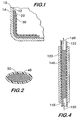
- FIG. 1 is a simplified, partial, cross-sectional view of a vessel in accordance with one embodiment of the present invention
- FIG. 2 is a simplified, enlarged, cross-sectional view of an encapsulated odorant capsule according to the present invention
- FIG. 3 is a simplified, cross-sectional view of a vessel in accordance with another embodiment of the present invention.
- FIG. 4 is a simplified, cross-sectional view of the odorant storage area shown in Fig. 3.
- odorant layer immobilized in a suitable carrier covers substantially all of the inner vessel surfaces and a semi-permeable or microporous material layer covers substantially all of the odorant layer, thereby substantially encapsulating the immobilized odorant material between the inner vessel wall and the semi-permeable or microporous material.
- the nature of the semi-permeable or microporous material is such that it permits the transportation of odorants through it while maintaining a composition and concentration of the odorant materials within the gas storage vessel which is in equilibrium with the sorbed or encapsulated odorant.
- the actual composition and concentration of the odorant in the gas space is dependent on the composition of the sorbed or encapsulated odorant, temperature and pressure of the storage vessel. These conditions are established in such a way that the gas in the vessel always contains a uniform and consistent concentration that is adequate to detect. Thus, the gas leaking from the vessel will have an odor detectable by the human sense of smell.
- a system for alerting of the existence of diffusion and distribution of the odorant in a vessel where the vessel has an interior volume and inner and outer vessel surfaces.
- An odorant encapsulated in discrete or continuous dimensions of the capsules containing the odorant is placed in the gas vessel.
- the odorant is encapsulated in the semi-permeable or the microporous material layer which covers substantially all of the odorant.
- the nature of the semi-permeable or microporous material is such that it permits the transportation of odorants through it while maintaining a composition and concentration of the odorant materials within the gas storage vessel which is in equilibrium with the encapsulated odorant.
- composition and concentration of the odorant in the gas space is dependent on the composition of the encapsulated odorant, temperature and pressure of the storage vessel. These conditions are established in such a way that the gas in the vessel always contains a uniform and consistent concentration that is adequate to detect the gas leaking from the vessel to have an odor detectable by the human sense of smell.
- a system for alerting of the existence of diffusion and distribution of the odorant in a vessel where the vessel has an interior volume and inner and outer vessel surfaces.
- An additional apparatus is provided in the gas storage vessel, such as a gas cylinder, where the encapsulated or sorbed odorant is placed in the path of the discharge gas.
- the gas exiting the vessel will pick up a certain required amount of the odorant that is adequate to detect the gas leaving from the vessel to have an odor detectable by the human sense of smell.
- the type and amount of the odorant can be determined on the basis of the desired composition and desired concentration in the gas leaving the vessel.
- a desired concentration is generally about 1-10 mg S/liter or more of gas.
- the odoriferous material can be added in the gas by any of the following methods.
- the odorant-encapsulated material is dispensed in the gas storage and delivery system by encapsulating it in an appropriate medium and a predetermined quantity of the encapsulated material is placed in the gas storage vessels in which the gas needs to be odorized.
- a key feature of the various methods described herein is that it offers a very large surface area for the gas and odorant contact, such that the condensed odorants offer a more uniform distribution of the odorant in the gas container.
- the odorant encapsulated material is in any appropriate shape or form.
- a built-in odorant dispenser is the reverse operation of the built-in purifiers that are used in the gas industry to purify the gas delivered from cylinders (as shown in Figure 2 of U.S. Pat. No. 5,409,526). Similar in design to a built-in purifier, the built-in odorant dispenser dispenses a predetermined amount of the odorant material to the gas as it exits the gas storage vessel. The odorant is sorbed (absorbed or adsorbed) on an appropriate carrier or is in the free or encapsulated state.
- the gas When gas exits the pressure vessel to be dispensed to the user application, the gas carries with it a predetermined amount of the odorant, which imparts a desired level of odor to the gas sufficient for the odor to be detected by the human sense of smell. The remaining gas in the storage vessel remains free of the odorant.
- a key advantage of this method is that it dispenses a uniform quantity of the odorant to the gas and eliminates the concerns associated with the non-uniformity of the odorant in the bulk gas caused by the condensation of the odorant or adsorption of the odorant on the storage vessel walls.
- FIG.1 shows a cross section of a wall 10 of a gas storage vessel.
- An odorant is encapsulated in material 20.
- the vessel wall 10 has an outer surface 14 and an inner surface 12.
- Material 20 containing odorant is placed (coated, overlaid, etc.) on the inner surface 12.
- An optional semi-permeable or microporous material 30 is placed over the encapsulated odorant in material 20.
- Material 30 freely permits the diffusion of odorant from material 20 without any substantial resistance.
- Figure 2 shows an individual capsule in which an odorant material 50 is encapsulated in a semi-permeable wall 40 such that the odorant is free to diffuse out of the semi-permeable wall.
- Figure 3 shows a partial section of a gas-containing vessel 100, such as a gas cylinder.
- a gas-containing vessel 100 such as a gas cylinder.
- an open-ended tube 110 is placed in a high pressure gas space.
- the section 120 (of tube 110) contains an encapsulated odorant and is connected to the gas regulator 130 via connector 122.
- Figure 4 is an enlarged view illustrating section 120 of tube 110 showing the encapsulated odorant 140.
- Gas 150 which does not contain odorant, travels through section 120 and picks up the odorant from the encapsulating odorant 140, and thereby carries with it odorant for odorant containing gas 160.
- Example 1 The odorant material is encapsulated in an appropriate material from which it is released and establishes an equilibrium with the gas stored in the vessel at the gas storage pressure and temperature.
- the encapsulation of the odorant material can be done by the known techniques in the literature.
- a solution of the odoriferous materials such as: mercaptans (tetrabutyl mercaptan, isopropyl mercaptan, normal propyl mercaptan, secondary butyl mercaptans, ethyl mercaptans, normal butyl mercaptan, etc.), thiophenes (tetrahydrothiophene), sulfides (dimethyl sulfide, methyl ethyl sulfide), and the like, and their combinations, and odorants selected from a group consisting of derivatives of acrylic acid, alkyl ethers of C 4 -C 7 , carboxylic acids, and combinations thereof, is made and applied on interior surfaces of a gas storage.vessel and its accessories.
- mercaptans tetrabutyl mercaptan, isopropyl mercaptan, normal propyl mercaptan, secondary butyl mercaptans, eth
- the odoriferous material solution is made at a concentration of 0.01 % w/w to 100 % w/w either in aqueous or non aqueous solvent/solvent mixtures of relatively high volatility solvents in which the odoriferous materials are soluble.
- solvents can be both polar and nonpolar solvents such that the odoriferous material solution is capable of wetting the surface of the gas vessel and its accessories and forming a continuous thin layer of liquid or semi-solid odorant on the surface.
- a thin film of the odorant solution is made on the various surfaces by contacting the odorant solution to the surfaces and drying out the solvents such that a continuous layer of the odorant is left on the surfaces.
- a single layer or multiple layers of the odorant is/are placed on the surfaces.
- the odorant layer is then sealed by coating over it a continuous layer of a semi-permeable or microporous polymeric or microporous non-polymeric material which has characteristics such that it permits the transport of the odorant through it.
- the thin encapsulating layer is formed on the odorant film, for example, using a rubbery polymer such as polydimethyl siloxane amongst other rubbery materials and glassy polymers such as polyimides, polysulfones, polyamides, polyarylates, polyolefins, polyether ketones, polytetraflouroethane, polydienes, and the like.
- an over coating is then made by dissolving a rubbery or glassy film forming polymer in an appropriate volatile solvent at a concentration ranging from 0.1 % to 10 % solution depending on the thickness, in such a way that the sealing layer does not act as a barrier to the transport of the odorant.
- the coating solution is then drained and the surfaces are dried by volatilization of the solvents, either by natural evaporation or by forced evaporation caused by heating the surfaces, using air or inert gas circulation or the combination thereof.
- the coatings can be done by a spray coating method or other methods known to those skilled in the coating art.
- Pre-prepared semi-permeably material layers in the form of membranes may also be placed on the odorant layer to encapsulate the odorant layer.
- Such semi-permeable membranes can either be commercially purchased or fabricated separately using the known art described, for example, in the references cited herein.
- Example 2 The odorant material can be sorbed with an appropriate substrate where it exists in a liquid condensed form and is held there by capillary forces. The thus odorant containing sorbed material is placed in the gas storage vessel in a predetermined quantity. At the temperature and pressure of the gas, the odorant material establishes equilibrium with the gas and provides the needed concentration of the odorant material required to generate an odor in the leaking gas.
- Example 3 The odorant material is immobilized by sorption or by encapsulation in a semi permeable lining which is placed or coated on the inside surfaces of gas storage vessels, piping, accessories (fittings, valves, etc.) and transfer hoses.
- the immobilized odorant material in the lining maintains a certain uniform concentration of the odorant in the gas depending on its properties and the storage temperature and pressure.
- the lining used for holding the immobilized odorant material can be of any appropriate media such as polymer, ceramic or metal.
- Example 4 The lining used in Example 3 is designed in such a way that it provides surface area of contact between the gas and the odorant which is larger than the surface area on which it is formed. This is done by providing surface structure on the coatings such as ribs and fins.
- the adsorbent substrate in the vessel and accessories is a macro porous cage or spongy structure with very high surface area per unit volume and is capable of sorbing odorant material on it.
- Example 6 The lining material in Example 3 does not have to fully adhere or stick to the surface of the vessel, etc.
- Example 7 The encapsulation /sorption media used in Example 1 as a sorbent for the odorant material is in any appropriate geometric shape or form.
- Example 8 A built in dispenser (of the design similar to that of a built in purifier) is used in a gas pressure vessel made of metal, reinforced plastic, or other structural material.
- the dispenser is placed in the pressure vessel in such a way that all the gas dispensed from the vessel must pass through the dispenser.
- the exit end of the dispenser therefore has the appropriate flow regulator valve to which a pressure/flow rate regulator can be mounted.
- the dispenser is made of glass, fiberglass, plastic or other structural material.
- the holding space in the dispenser is filled with one or more of the odorant materials or their blends used for the odorization of the gas.
- the barrier layer of the said dispenser therefore separates the gas in the vessel and the odorant material.
- odorant material carried by the gas is regulated by the selection of the characteristics of the odorant material (such as vapor pressure dispensing temperature, etc.) and the design of the dispenser ( gas contacting efficiency, residence time, etc.).
- the dispensing gas is mixed appropriately with the odorant material at the sensing levels of the human sense of smell and hence is detectable by smell.
- Example 9 A nonodorant liquid dilutes the odorant material in Example 8.
- Example 10 A solid sorbent or adsorbent is used for the odorant material in the dispenser in Example 8.
- Example 11 The odorant material is microencapsulated in an appropriate media and is filled in the dispenser of Example 8.
- a gas-liquid contactor is used in the built-in-dispenser as a mass transfer device between the gas and the odorant material for the transfer of the odorant to the gas when the odorant used is in the liquid state.
- a contactor is made of a gas sparger ( plastic, ceramic, or metal) and/ or a membrane based gas-liquid contactor.
Landscapes
- Physics & Mathematics (AREA)
- General Physics & Mathematics (AREA)
- Feeding, Discharge, Calcimining, Fusing, And Gas-Generation Devices (AREA)
- Emergency Alarm Devices (AREA)
Applications Claiming Priority (2)
| Application Number | Priority Date | Filing Date | Title |
|---|---|---|---|
| US321418 | 2002-12-16 | ||
| US10/321,418 US7192459B2 (en) | 2002-12-16 | 2002-12-16 | Addition of odorants to gases for leak detection |
Publications (2)
| Publication Number | Publication Date |
|---|---|
| EP1431738A2 true EP1431738A2 (de) | 2004-06-23 |
| EP1431738A3 EP1431738A3 (de) | 2006-01-18 |
Family
ID=32393003
Family Applications (1)
| Application Number | Title | Priority Date | Filing Date |
|---|---|---|---|
| EP03028748A Withdrawn EP1431738A3 (de) | 2002-12-16 | 2003-12-12 | Zusatz von Gerauchstoffen zu Gasen zur Leckerfassung |
Country Status (3)
| Country | Link |
|---|---|
| US (1) | US7192459B2 (de) |
| EP (1) | EP1431738A3 (de) |
| CA (1) | CA2452464A1 (de) |
Families Citing this family (23)
| Publication number | Priority date | Publication date | Assignee | Title |
|---|---|---|---|---|
| US7915047B2 (en) | 2007-11-19 | 2011-03-29 | Los Alamos National Security, Llc | Coating for leak detection and method |
| US20100280509A1 (en) * | 2009-04-02 | 2010-11-04 | Avedro, Inc. | Eye Therapy System |
| AU2010336001B2 (en) * | 2009-12-21 | 2014-11-06 | Shreepad Krishna Bhat | Leak detection device |
| CN113586964A (zh) * | 2020-04-30 | 2021-11-02 | 田野 | 采暖水地下管道检查漏点的气味指示剂及其制备方法 |
| US11760169B2 (en) | 2020-08-20 | 2023-09-19 | Denso International America, Inc. | Particulate control systems and methods for olfaction sensors |
| US11813926B2 (en) | 2020-08-20 | 2023-11-14 | Denso International America, Inc. | Binding agent and olfaction sensor |
| US12377711B2 (en) | 2020-08-20 | 2025-08-05 | Denso International America, Inc. | Vehicle feature control systems and methods based on smoking |
| US11760170B2 (en) | 2020-08-20 | 2023-09-19 | Denso International America, Inc. | Olfaction sensor preservation systems and methods |
| US12269315B2 (en) | 2020-08-20 | 2025-04-08 | Denso International America, Inc. | Systems and methods for measuring and managing odor brought into rental vehicles |
| US12251991B2 (en) | 2020-08-20 | 2025-03-18 | Denso International America, Inc. | Humidity control for olfaction sensors |
| US11636870B2 (en) | 2020-08-20 | 2023-04-25 | Denso International America, Inc. | Smoking cessation systems and methods |
| US11881093B2 (en) | 2020-08-20 | 2024-01-23 | Denso International America, Inc. | Systems and methods for identifying smoking in vehicles |
| US11828210B2 (en) | 2020-08-20 | 2023-11-28 | Denso International America, Inc. | Diagnostic systems and methods of vehicles using olfaction |
| US11932080B2 (en) | 2020-08-20 | 2024-03-19 | Denso International America, Inc. | Diagnostic and recirculation control systems and methods |
| US12017506B2 (en) | 2020-08-20 | 2024-06-25 | Denso International America, Inc. | Passenger cabin air control systems and methods |
| US12037128B2 (en) | 2021-03-23 | 2024-07-16 | General Electric Company | Safety markers for a hydrogen fuel system |
| US11732652B2 (en) | 2021-03-23 | 2023-08-22 | General Electric Company | Removing safety markers from a hydrogen fuel system |
| US12264588B2 (en) | 2022-03-07 | 2025-04-01 | General Electric Company | Liquid fluid systems including phase detection sensors for turbine engines |
| US11788474B2 (en) | 2022-03-07 | 2023-10-17 | General Electric Company | Pericritical fluid systems for turbine engines |
| US12018594B2 (en) | 2022-03-07 | 2024-06-25 | General Electric Company | Pericritical fluid systems for turbine engines |
| US11946378B2 (en) | 2022-04-13 | 2024-04-02 | General Electric Company | Transient control of a thermal transport bus |
| US11927142B2 (en) | 2022-07-25 | 2024-03-12 | General Electric Company | Systems and methods for controlling fuel coke formation |
| US12253033B2 (en) | 2022-10-04 | 2025-03-18 | General Electric Company | Hydrogen fuel leak detection system for a vehicle |
Family Cites Families (18)
| Publication number | Priority date | Publication date | Assignee | Title |
|---|---|---|---|---|
| US3169839A (en) * | 1959-09-23 | 1965-02-16 | George W Benz | Odorizing of liquified gas |
| US3112189A (en) * | 1960-03-14 | 1963-11-26 | Inst Gas Technology | Odorization of pipeline gas |
| US3578545A (en) * | 1968-08-19 | 1971-05-11 | Carson Saeks Inc | Flexible odor-liberating laminate |
| US3854894A (en) * | 1970-04-06 | 1974-12-17 | D Klass | Permeant gas method and apparatus |
| US3669637A (en) * | 1970-05-08 | 1972-06-13 | Inst Gas Technology | Odorant replacement in gas streams |
| US4487613A (en) * | 1983-09-26 | 1984-12-11 | International Flavors & Fragrances Inc. | Odorization of combustible hydrocarbon gases |
| FR2613070B1 (fr) | 1987-03-23 | 1991-02-08 | Provost Camille | Dispositif pour detecter une fuite de gaz |
| US5361527A (en) * | 1988-05-31 | 1994-11-08 | Burgeson John R | Temperature regulated scent dispenser |
| JP2864164B2 (ja) * | 1990-11-05 | 1999-03-03 | 理研香料工業株式会社 | 燃料ガス用付臭剤 |
| DE4135796A1 (de) * | 1991-10-30 | 1993-05-06 | Goetz-Ulrich London Gb Wittek | Verfahren und vorrichtung fuer die ereignisbezogene oder szenengenaue duftdarbietung bei cinematographischen auffuehrungen und dergleichen |
| FR2758478B1 (fr) * | 1997-01-21 | 1999-02-26 | Elf Aquitaine | Procede pour la presulfuration de catalyseurs |
| DE19837066A1 (de) | 1998-08-17 | 2000-02-24 | Haarmann & Reimer Gmbh | Odorierung von Gas |
| US6063365A (en) * | 1998-09-10 | 2000-05-16 | International Flavors & Fragrances Inc. | Application of film forming technology to fragrance control release systems; and resultant fragrance control release systems |
| US6006374A (en) * | 1998-09-23 | 1999-12-28 | Winnett; Harold G. | Showerhead attachment and method for generating aromas |
| US6063632A (en) * | 1998-11-12 | 2000-05-16 | Perkins; Gary | Water leak detection |
| JP2000233901A (ja) | 1999-02-10 | 2000-08-29 | Sanyo Electric Co Ltd | 水素製造装置および燃料電池システムならびにこれらの運転方法 |
| US6142162A (en) * | 1999-06-18 | 2000-11-07 | Odoreyes Technology, Inc. | System and method for odorizing natural gas |
| US20040084083A1 (en) * | 2002-07-15 | 2004-05-06 | Ballard Power Systems Inc. | Distribution of non-odorized gas |
-
2002
- 2002-12-16 US US10/321,418 patent/US7192459B2/en not_active Expired - Fee Related
-
2003
- 2003-12-09 CA CA002452464A patent/CA2452464A1/en not_active Abandoned
- 2003-12-12 EP EP03028748A patent/EP1431738A3/de not_active Withdrawn
Also Published As
| Publication number | Publication date |
|---|---|
| EP1431738A3 (de) | 2006-01-18 |
| CA2452464A1 (en) | 2004-06-16 |
| US20040115820A1 (en) | 2004-06-17 |
| US7192459B2 (en) | 2007-03-20 |
Similar Documents
| Publication | Publication Date | Title |
|---|---|---|
| US7192459B2 (en) | Addition of odorants to gases for leak detection | |
| US7229831B2 (en) | Leak site odorization for gas leak detection | |
| CA2452463C (en) | Leak detection by reactions at the leak site | |
| EP1434044A2 (de) | Doppelwandigen Behältern für Geruchsstoffe | |
| US7024869B2 (en) | Addition of odorants to hydrogen by incorporating odorants with hydrogen storage materials | |
| US11840399B2 (en) | Gas blanketing management of low-pressure hydrocarbon tanks | |
| Jung et al. | Two volumetric techniques for determining the transport properties of hydrogen gas in polymer | |
| Tamaddoni et al. | Experimental study of the VOC emitted from crude oil tankers | |
| US10036509B2 (en) | Nitrogen blanketing system | |
| Patil et al. | New AMP/polyamine blends for improved CO2 capture: Study of kinetic and equilibrium features | |
| US6820464B2 (en) | Odorized seals for the detection of gas leak | |
| Laine et al. | Permeability of polyethylene film to organic vapors | |
| CA2452462A1 (en) | Double walled vessels for odorant containments | |
| RU2466074C2 (ru) | Аварийное устройство для воздействия на утечку опасных химических веществ | |
| US3669637A (en) | Odorant replacement in gas streams | |
| KR20070086873A (ko) | 펜타보란(9)의 저장 및 급송 장치와 그 방법 | |
| JP2002128501A (ja) | ガス吸蔵方法及び燃料電池 | |
| JPH0622193Y2 (ja) | 容器の漏洩検知装置 | |
| Filipiuk | THE PROBLEM OF STORING LIQUID FUELS | |
| KR20180000193U (ko) | 도시가스 부취제 탈취장치 | |
| Wiegleb | Physical Properties of Gases | |
| KR20200050099A (ko) | 부취제 주입 장치 | |
| CA2196941A1 (en) | Dual containment assembly | |
| CZ164598A3 (cs) | Způsob odorizace a zařízení k provádění způsobu | |
| Dixit | Upgrading Biogas to Biomethane Using Absorption |
Legal Events
| Date | Code | Title | Description |
|---|---|---|---|
| PUAI | Public reference made under article 153(3) epc to a published international application that has entered the european phase |
Free format text: ORIGINAL CODE: 0009012 |
|
| AK | Designated contracting states |
Kind code of ref document: A2 Designated state(s): AT BE BG CH CY CZ DE DK EE ES FI FR GB GR HU IE IT LI LU MC NL PT RO SE SI SK TR |
|
| AX | Request for extension of the european patent |
Extension state: AL LT LV MK |
|
| PUAL | Search report despatched |
Free format text: ORIGINAL CODE: 0009013 |
|
| AK | Designated contracting states |
Kind code of ref document: A3 Designated state(s): AT BE BG CH CY CZ DE DK EE ES FI FR GB GR HU IE IT LI LU MC NL PT RO SE SI SK TR |
|
| AX | Request for extension of the european patent |
Extension state: AL LT LV MK |
|
| 17P | Request for examination filed |
Effective date: 20060207 |
|
| AKX | Designation fees paid |
Designated state(s): AT BE BG CH CY CZ DE DK EE ES FI FR GB GR HU IE IT LI LU MC NL PT RO SE SI SK TR |
|
| STAA | Information on the status of an ep patent application or granted ep patent |
Free format text: STATUS: THE APPLICATION IS DEEMED TO BE WITHDRAWN |
|
| 18D | Application deemed to be withdrawn |
Effective date: 20100701 |