EP1431791A2 - Zentrales Verstärkungselement für Glasfaserkabel - Google Patents
Zentrales Verstärkungselement für Glasfaserkabel Download PDFInfo
- Publication number
- EP1431791A2 EP1431791A2 EP03027762A EP03027762A EP1431791A2 EP 1431791 A2 EP1431791 A2 EP 1431791A2 EP 03027762 A EP03027762 A EP 03027762A EP 03027762 A EP03027762 A EP 03027762A EP 1431791 A2 EP1431791 A2 EP 1431791A2
- Authority
- EP
- European Patent Office
- Prior art keywords
- strength member
- reinforcing fibers
- matrix material
- oriented
- strength
- Prior art date
- Legal status (The legal status is an assumption and is not a legal conclusion. Google has not performed a legal analysis and makes no representation as to the accuracy of the status listed.)
- Withdrawn
Links
- 230000003287 optical effect Effects 0.000 title 1
- 239000012783 reinforcing fiber Substances 0.000 claims abstract description 44
- 239000011159 matrix material Substances 0.000 claims abstract description 31
- 239000000835 fiber Substances 0.000 claims abstract description 17
- 239000011521 glass Substances 0.000 claims description 8
- 239000000463 material Substances 0.000 claims description 7
- 239000011248 coating agent Substances 0.000 claims description 6
- 238000000576 coating method Methods 0.000 claims description 6
- 239000013307 optical fiber Substances 0.000 claims description 4
- 239000011347 resin Substances 0.000 claims description 4
- 229920005989 resin Polymers 0.000 claims description 4
- OKTJSMMVPCPJKN-UHFFFAOYSA-N Carbon Chemical compound [C] OKTJSMMVPCPJKN-UHFFFAOYSA-N 0.000 claims description 2
- 239000004593 Epoxy Substances 0.000 claims description 2
- 239000004760 aramid Substances 0.000 claims description 2
- 229920003235 aromatic polyamide Polymers 0.000 claims description 2
- 229910052799 carbon Inorganic materials 0.000 claims description 2
- 229920000728 polyester Polymers 0.000 claims description 2
- 210000002268 wool Anatomy 0.000 claims description 2
- 239000012815 thermoplastic material Substances 0.000 claims 1
- 239000007787 solid Substances 0.000 abstract description 5
- 239000012634 fragment Substances 0.000 abstract description 3
- 239000004033 plastic Substances 0.000 abstract description 3
- 229920003023 plastic Polymers 0.000 abstract description 3
- 239000002131 composite material Substances 0.000 description 3
- 239000011152 fibreglass Substances 0.000 description 3
- 239000000203 mixture Substances 0.000 description 3
- 239000006223 plastic coating Substances 0.000 description 3
- -1 polyethylenes Polymers 0.000 description 2
- 229920001169 thermoplastic Polymers 0.000 description 2
- 239000004416 thermosoftening plastic Substances 0.000 description 2
- 239000004698 Polyethylene Substances 0.000 description 1
- 239000004743 Polypropylene Substances 0.000 description 1
- 239000011230 binding agent Substances 0.000 description 1
- 150000001875 compounds Chemical class 0.000 description 1
- 230000003247 decreasing effect Effects 0.000 description 1
- 229920000573 polyethylene Polymers 0.000 description 1
- 229920001155 polypropylene Polymers 0.000 description 1
- 230000003014 reinforcing effect Effects 0.000 description 1
Images


Classifications
-
- G—PHYSICS
- G02—OPTICS
- G02B—OPTICAL ELEMENTS, SYSTEMS OR APPARATUS
- G02B6/00—Light guides; Structural details of arrangements comprising light guides and other optical elements, e.g. couplings
- G02B6/44—Mechanical structures for providing tensile strength and external protection for fibres, e.g. optical transmission cables
- G02B6/4401—Optical cables
- G02B6/4429—Means specially adapted for strengthening or protecting the cables
- G02B6/4434—Central member to take up tensile loads
Definitions
- the present invention relates generally to central strength members for fiber optic cables, and more specifically to central strength members having non-longitudinally oriented glass filaments for increasing torsional strength.
- Fiber optic cables have been used by the telecommunications industry for a number of years to transmit information at very high rates over long distances.
- Fiber optic cables come in a variety of configurations, including: cables with a centrally located single buffer tube containing one or more optical fibers; cables with a plurality of buffer tubes stranded in a helical or alternating helical arrangement about a central strength member; and cables with slotted cores in which a plurality of optical fibers reside.
- Strength members provide tensile strength and stability to a fiber optic cable.
- the strength member is surrounded by plurality of stranded buffer tubes containing optical fibers.
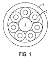
- the buffer tubes and strength member are disposed within a fiber optic cable as shown in Figure 1. It can be seen that the fiber optic cable 1 contains a plurality of buffer tubes 3 stranded around a central strength member 2. When disposed in the center of a plurality of buffer tubes 3, the strength member 2 is often referred to as a central strength member 2.
- the central strength member 2 is usually a solid rigid rod composed of a composite of reinforcing fibers encapsulated in a matrix material.
- a common example of such a composition would be a composite of glass filaments in a resin material. This composite is called glass reinforced plastic or GRP.
- the diameter of the strength member 2 varies depending on the number of required buffer tubes 3.
- the strength member 2 is either a solid rod having the correct diameter to accommodate the required buffer tubes 3 or a solid rod having a smaller diameter than required but having a soft plastic coating to bring the diameter up to the correct diameter.
- Using a soft plastic coating to replace part of the strength member 2 reduces the overall weight of the strength member 2 which is sometimes desired. Additionally, the strength member 2 is generally made of expensive material and thus, by reducing the size of the strength member 2, the overall cost of the fiber optic cable 1 is also reduced.
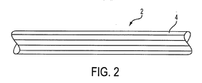
- the strength member is made of a large number of glass filaments oriented in a longitudinal direction within the resin as shown in Figure 2.
- the glass filaments 4 are oriented parallel with each other and parallel to the axis of the strength member 2.
- the glass filaments 4 are continuous down the length of the strength member 2.
- the strength member 2 is strong in the longitudinal (or axial) direction (i.e. in tension) but very weak in torsion (i.e. twisting). Therefore, it is desirable to have a central strength member 2 that has increased torsional strength.
- the strength member of the present invention can be designed in a number of ways to give strength in both tension and torsion.
- the reinforcing fibers of the strength member can be oriented in a non-longitudinal manner, such as in a cross-helical pattern, within the matrix material. This results in increased strength in both tension and torsion.
- chopped reinforcing fibers are randomly oriented within the matrix material. Chopped reinforcing fibers are short sections or fragments of the reinforcing fibers.
- the strength member can be designed to have a hollow core or center. Said differently, the strength member is not solid in cross-section but instead has a hollow core or center. With a hollow core, the strength member can have any type of orientation for its reinforcing fibers, including longitudinally orienting the reinforcing fibers within the matrix material. These strength member designs provides the desired strength in both tension and torsion.
- a fiber optic cable 1 is illustrated having a plurality of buffer tubes 3 and a central strength member 2. As shown, the buffer tubes 3 are stranded around the central strength member 2. The size, shape, number and orientation of the buffer tubes 3 are not limited in the present invention. Additionally, although Figure 1 shows a central strength member 2, the strength member 2 is not limited to being disposed in the center of the buffer tubes 3 or center of the fiber optic cable 1. The strength member 2 may be arranged, sized or shaped in any desired manner within the fiber optic cable and more than one strength member 2 may be used. Furthermore, the fiber optic cable 1 may have other components disposed therein such as gel compounds, tapes, yarns...etc.
- the strength member 2 is made of reinforcing fibers 4 disposed within a matrix material 5.
- the reinforcing fibers 4 are oriented in a non-longitudinal manner. Said differently, the reinforcing fibers 4 are not oriented parallel to the longitudinal or axial direction of the strength member 2.
- the reinforcing members 4 can preferably be oriented in a cross-helical pattern within the matrix material 5.
- the matrix material 5 is a binder material that encompasses the reinforcing fibers 4.
- the matrix material 5 can be many different types of materials, such as resins, epoxy, and thermoplastics.
- the reinforcing fibers 4 can be many different types of materials, such as glass, wool, carbon, aramid and polyester.
- reinforcing fibers 4 are disposed within a matrix material 5.
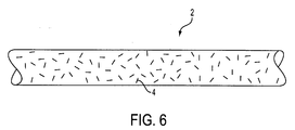
- the reinforcing fibers 4 are chopped, that is, the reinforcing fibers 4 are short fragments of longer reinforcing fibers 4.
- Each "chopped" reinforcing fiber 4 is generally shorter in length than the cross-sectional diameter of the strength member 2.
- the "chopped" reinforcing fibers 4 are randomly-oriented within the matrix material 5. By providing this random orientation, the strength member 2 becomes stronger in both tension and torsion.
- a strength member 2 is shown having an outer coating 6.
- the outer coating 6 is generally made from a softer thermoplastic, such as polyethylenes or polypropylenes, and is provided to adjust the cross-sectional diameter of the strength member 2 to the desired size. Additionally, the outer coating 6 can replace part of the glass reinforced plastic 5, thereby creating a lighter strength member 2. For example, many times, a large heavy strength member 2 is not needed in a fiber optic cable 1. In these circumstances, it is often desirable to use a lighter strength member 2 while not decreasing the cross-sectional diameter of the strength member 2. Accordingly, a light plastic coating 6 is disposed on the outer surface of the glass reinforced plastic 5 (or any other type of strength member, not limited to glass reinforce plastic). As a result, the cross-sectional diameter of the strength member 2 remains the same while some of the heavy GRP 5 is essentially replaced by a lighter plastic outer coating 6.
- a strength member 2 is shown having a hollow core 7.
- Another way to increase the strength of the strength member 2 in torsion and tension is to design the strength member 2 to have hollow core 7 which runs in the longitudinal direction of the strength member 2.
- the cross-sectional diameter of the hollow core 7 can be varied in size and shape.
- the composition of the strength member 2 can be any of the previously described compositions.
- the reinforcing fibers 4 can be oriented in any of the previously described manners.
- the reinforcing fibers 4 can be oriented in the longitudinal direction since the hollow core 7 structure gives the strength member 2 increased strength in torsion. Accordingly, the reinforcing fibers 4 oriented in the longitudinal direction would provide the needed strength in tension and the hollow core design would provide the needed strength in torsion.
Landscapes
- Physics & Mathematics (AREA)
- General Physics & Mathematics (AREA)
- Optics & Photonics (AREA)
- Ropes Or Cables (AREA)
Applications Claiming Priority (2)
| Application Number | Priority Date | Filing Date | Title |
|---|---|---|---|
| US322511 | 2002-12-19 | ||
| US10/322,511 US20040120664A1 (en) | 2002-12-19 | 2002-12-19 | Anti-rotational central strength member |
Publications (2)
| Publication Number | Publication Date |
|---|---|
| EP1431791A2 true EP1431791A2 (de) | 2004-06-23 |
| EP1431791A3 EP1431791A3 (de) | 2004-07-07 |
Family
ID=32393019
Family Applications (1)
| Application Number | Title | Priority Date | Filing Date |
|---|---|---|---|
| EP03027762A Withdrawn EP1431791A3 (de) | 2002-12-19 | 2003-12-03 | Zentrales Verstärkungselement für Glasfaserkabel |
Country Status (2)
| Country | Link |
|---|---|
| US (1) | US20040120664A1 (de) |
| EP (1) | EP1431791A3 (de) |
Cited By (1)
| Publication number | Priority date | Publication date | Assignee | Title |
|---|---|---|---|---|
| US20230042562A1 (en) * | 2020-02-06 | 2023-02-09 | Fujikura Ltd. | Optical fiber cable and method of manufacturing optical fiber cable |
Families Citing this family (4)
| Publication number | Priority date | Publication date | Assignee | Title |
|---|---|---|---|---|
| US7421169B2 (en) * | 2003-06-20 | 2008-09-02 | Fujikura Ltd. | Optical fiber cable |
| EP2471203B1 (de) | 2009-08-25 | 2016-07-06 | Xieon Networks S.à r.l. | Verfahren und anordnung für raman-verstärkungsmessung und -überwachung während eines dienstes |
| CN103221460B (zh) * | 2010-09-29 | 2015-11-25 | 陶氏环球技术有限责任公司 | 用于缆线的柔性加强件 |
| CA3262124A1 (en) | 2022-07-14 | 2024-01-18 | Commscope Technologies Llc | OPTIMIZED LOW FIBER COUNT LOOSE TUBE FIBER CABLE |
Citations (5)
| Publication number | Priority date | Publication date | Assignee | Title |
|---|---|---|---|---|
| US4514035A (en) * | 1981-10-07 | 1985-04-30 | Siemens Aktiengesellschaft | Cable with an outer jacket of gnaw resistant material |
| GB2157848A (en) * | 1984-04-19 | 1985-10-30 | Pirelli Cavi Spa | Underwater optical fibre cable |
| US4769286A (en) * | 1985-02-21 | 1988-09-06 | Georges Le Noane | Composite reinforcing elements and processes for producing them |
| EP0968809A1 (de) * | 1998-07-01 | 2000-01-05 | Alcatel | Zusammengefügtes kontinuierliches und verstärktes Hüllrohr für faseroptische Kabel |
| US6324324B1 (en) * | 2000-01-12 | 2001-11-27 | Lucent Technologies Inc. | Communication cable having reduced jacket shrinkage |
Family Cites Families (19)
| Publication number | Priority date | Publication date | Assignee | Title |
|---|---|---|---|---|
| US4000936A (en) * | 1974-07-30 | 1977-01-04 | Bell Telephone Laboratories, Incorporated | Optical fiber jacket designs for minimum distortion loss |
| US4082423A (en) * | 1976-08-19 | 1978-04-04 | The United States Of America As Represented By The Secretary Of The Navy | Fiber optics cable strengthening method and means |
| US4252871A (en) * | 1979-06-18 | 1981-02-24 | Koehler Manufacturing Company | Tubular support sleeve for lead-acid storage battery |
| US4910057A (en) * | 1982-04-02 | 1990-03-20 | Hoechst Celanese Corporation | Melt extruded elongated member suitable for improved service as a stiffening support in an optical fiber cable |
| WO1989007778A1 (fr) * | 1988-02-10 | 1989-08-24 | Fujitsu Limited | Cable en fibre optique et production de ce cable |
| US5440660A (en) * | 1988-05-23 | 1995-08-08 | The United States Of America As Represented By The Secretary Of Navy | Fiber optic microcable produced with fiber reinforced ultraviolet light cured resin and method for manufacturing same |
| US5109457A (en) * | 1988-12-14 | 1992-04-28 | At&T Bell Laboratories | All-dielectric optical fiber cable having enhanced fiber access |
| IT1228878B (it) * | 1989-03-24 | 1991-07-05 | Pirelli Cavi Spa | Perfezionamento nelle strutture di supporto di fibre ottiche per funi di guardia e per cavi a fibre ottiche. |
| US4960318A (en) * | 1989-04-25 | 1990-10-02 | Alcatel Na, Inc. | Optical fiber cable |
| US5148509A (en) * | 1991-03-25 | 1992-09-15 | Corning Incorporated | Composite buffer optical fiber cables |
| US5390273A (en) * | 1992-04-02 | 1995-02-14 | Pirelli Cable Corporation | Flame resistant optical fiber cable with optical fibers loosely enclosed in tubes |
| US5642452A (en) * | 1995-02-21 | 1997-06-24 | Sumitomo Electric Lightwave Corp. | Water-blocked optical fiber communications cable |
| US5621841A (en) * | 1995-09-20 | 1997-04-15 | Siecor Corporation | Optical fiber cable containing ribbons in stranded tubes |
| US5751879A (en) * | 1995-12-28 | 1998-05-12 | Lucent Technologies Inc. | Wound optical fiber cable including robust component cable(s) and a system for manufacture of the cable |
| US5917977A (en) * | 1997-09-16 | 1999-06-29 | Siecor Corporation | Composite cable |
| US6249629B1 (en) * | 1998-12-10 | 2001-06-19 | Siecor Operations, Llc | Robust fiber optic cables |
| US20020154873A1 (en) * | 2001-01-26 | 2002-10-24 | Fiber-Line, Inc. | Core enclosures and methods for making the same |
| US6748147B2 (en) * | 2001-03-30 | 2004-06-08 | Corning Cable Systems Llc | High strength fiber optic cable |
| US6901191B2 (en) * | 2001-11-12 | 2005-05-31 | Corning Cable Systems Llc | High density fiber optic cable |
-
2002
- 2002-12-19 US US10/322,511 patent/US20040120664A1/en not_active Abandoned
-
2003
- 2003-12-03 EP EP03027762A patent/EP1431791A3/de not_active Withdrawn
Patent Citations (5)
| Publication number | Priority date | Publication date | Assignee | Title |
|---|---|---|---|---|
| US4514035A (en) * | 1981-10-07 | 1985-04-30 | Siemens Aktiengesellschaft | Cable with an outer jacket of gnaw resistant material |
| GB2157848A (en) * | 1984-04-19 | 1985-10-30 | Pirelli Cavi Spa | Underwater optical fibre cable |
| US4769286A (en) * | 1985-02-21 | 1988-09-06 | Georges Le Noane | Composite reinforcing elements and processes for producing them |
| EP0968809A1 (de) * | 1998-07-01 | 2000-01-05 | Alcatel | Zusammengefügtes kontinuierliches und verstärktes Hüllrohr für faseroptische Kabel |
| US6324324B1 (en) * | 2000-01-12 | 2001-11-27 | Lucent Technologies Inc. | Communication cable having reduced jacket shrinkage |
Cited By (1)
| Publication number | Priority date | Publication date | Assignee | Title |
|---|---|---|---|---|
| US20230042562A1 (en) * | 2020-02-06 | 2023-02-09 | Fujikura Ltd. | Optical fiber cable and method of manufacturing optical fiber cable |
Also Published As
| Publication number | Publication date |
|---|---|
| US20040120664A1 (en) | 2004-06-24 |
| EP1431791A3 (de) | 2004-07-07 |
Similar Documents
| Publication | Publication Date | Title |
|---|---|---|
| US5982966A (en) | Asymmetric structure fiber optic cable | |
| US4693551A (en) | Dielectric strength elements for loose tube optical fiber cable | |
| CN1020961C (zh) | 光缆 | |
| US5751880A (en) | Optical unit for an optical fiber telecommunications cable, and an optical fiber cable including such a unit | |
| US4093342A (en) | Optical fiber cable | |
| US6658187B2 (en) | Optical fiber cable assembly with interstitial support members | |
| US20130163932A1 (en) | Optical fiber cable and interconnect assembly | |
| US5016973A (en) | Cable reinforcement for an optical fiber cable | |
| KR100490136B1 (ko) | 비금속 자기지지형 광케이블 | |
| US20030044139A1 (en) | Dielectric optical fiber cable having reduced preferential bending | |
| US7359600B2 (en) | Loose tube optical cable having straight aggregation structure | |
| EP1152272A2 (de) | Verstärktes gepuffertes faseroptisches Bandkabel | |
| EP1359449A2 (de) | Verbessertes faseroptisches Kabel | |
| EP1288690B1 (de) | Optisches Hohladerkabel mit Faserbändchen | |
| US5113468A (en) | Fibre-optic cable assemblies | |
| EP1431791A2 (de) | Zentrales Verstärkungselement für Glasfaserkabel | |
| US6611646B1 (en) | Hybrid strength member for an optical cable | |
| US6987916B2 (en) | Fiber optic central tube cable with bundled support member | |
| EP0005029A1 (de) | Optische Faserkabel | |
| WO2010101092A1 (ja) | 単一チューブを伴う光ファイバケーブル | |
| KR100560668B1 (ko) | 고밀도 광섬유 케이블 | |
| GB2179072A (en) | Optical fibre cables | |
| US6002825A (en) | Optical cable | |
| KR20000046917A (ko) | 고강도 광섬유 케이블 | |
| DE3315473A1 (de) | Selbsttragendes lichtwellenleiterkabel |
Legal Events
| Date | Code | Title | Description |
|---|---|---|---|
| PUAI | Public reference made under article 153(3) epc to a published international application that has entered the european phase |
Free format text: ORIGINAL CODE: 0009012 |
|
| PUAL | Search report despatched |
Free format text: ORIGINAL CODE: 0009013 |
|
| AK | Designated contracting states |
Kind code of ref document: A2 Designated state(s): AT BE BG CH CY CZ DE DK EE ES FI FR GB GR HU IE IT LI LU MC NL PT RO SE SI SK TR |
|
| AX | Request for extension of the european patent |
Extension state: AL LT LV MK |
|
| AK | Designated contracting states |
Kind code of ref document: A3 Designated state(s): AT BE BG CH CY CZ DE DK EE ES FI FR GB GR HU IE IT LI LU MC NL PT RO SE SI SK TR |
|
| AX | Request for extension of the european patent |
Extension state: AL LT LV MK |
|
| 17P | Request for examination filed |
Effective date: 20041116 |
|
| AKX | Designation fees paid |
Designated state(s): AT BE BG CH CY CZ DE DK EE ES FI FR GB GR HU IE IT LI LU MC NL PT RO SE SI SK TR |
|
| RAP1 | Party data changed (applicant data changed or rights of an application transferred) |
Owner name: DRAKA COMTEQ B.V. |
|
| RAP1 | Party data changed (applicant data changed or rights of an application transferred) |
Owner name: DRAKA COMTEQ B.V. |
|
| RAP1 | Party data changed (applicant data changed or rights of an application transferred) |
Owner name: DRAKA COMTEQ B.V. |
|
| 17Q | First examination report despatched |
Effective date: 20080103 |
|
| STAA | Information on the status of an ep patent application or granted ep patent |
Free format text: STATUS: THE APPLICATION IS DEEMED TO BE WITHDRAWN |
|
| 18D | Application deemed to be withdrawn |
Effective date: 20090613 |