EP1431792A2 - Câble dissociable - Google Patents
Câble dissociable Download PDFInfo
- Publication number
- EP1431792A2 EP1431792A2 EP03027894A EP03027894A EP1431792A2 EP 1431792 A2 EP1431792 A2 EP 1431792A2 EP 03027894 A EP03027894 A EP 03027894A EP 03027894 A EP03027894 A EP 03027894A EP 1431792 A2 EP1431792 A2 EP 1431792A2
- Authority
- EP
- European Patent Office
- Prior art keywords
- cable
- communications
- connection portion
- load bearing
- ripcord
- Prior art date
- Legal status (The legal status is an assumption and is not a legal conclusion. Google has not performed a legal analysis and makes no representation as to the accuracy of the status listed.)
- Ceased
Links
- 238000004891 communication Methods 0.000 claims abstract description 41
- KAATUXNTWXVJKI-UHFFFAOYSA-N cypermethrin Chemical compound CC1(C)C(C=C(Cl)Cl)C1C(=O)OC(C#N)C1=CC=CC(OC=2C=CC=CC=2)=C1 KAATUXNTWXVJKI-UHFFFAOYSA-N 0.000 claims abstract description 27
- 238000000926 separation method Methods 0.000 claims abstract description 9
- 239000013307 optical fiber Substances 0.000 claims description 7
- 230000003014 reinforcing effect Effects 0.000 claims description 5
- RYGMFSIKBFXOCR-UHFFFAOYSA-N Copper Chemical compound [Cu] RYGMFSIKBFXOCR-UHFFFAOYSA-N 0.000 claims description 3
- 229910052802 copper Inorganic materials 0.000 claims description 3
- 239000010949 copper Substances 0.000 claims description 3
- 229910000838 Al alloy Inorganic materials 0.000 claims description 2
- OKTJSMMVPCPJKN-UHFFFAOYSA-N Carbon Chemical compound [C] OKTJSMMVPCPJKN-UHFFFAOYSA-N 0.000 claims description 2
- 229910000881 Cu alloy Inorganic materials 0.000 claims description 2
- 229910052782 aluminium Inorganic materials 0.000 claims description 2
- XAGFODPZIPBFFR-UHFFFAOYSA-N aluminium Chemical compound [Al] XAGFODPZIPBFFR-UHFFFAOYSA-N 0.000 claims description 2
- 239000004760 aramid Substances 0.000 claims description 2
- 229920003235 aromatic polyamide Polymers 0.000 claims description 2
- 229910052799 carbon Inorganic materials 0.000 claims description 2
- 239000000835 fiber Substances 0.000 claims description 2
- 239000011521 glass Substances 0.000 claims description 2
- 229920000728 polyester Polymers 0.000 claims description 2
- 229920000642 polymer Polymers 0.000 claims description 2
- 239000004033 plastic Substances 0.000 description 3
- 229920003023 plastic Polymers 0.000 description 3
- 238000000034 method Methods 0.000 description 2
- 229920002430 Fibre-reinforced plastic Polymers 0.000 description 1
- 208000034693 Laceration Diseases 0.000 description 1
- 239000004698 Polyethylene Substances 0.000 description 1
- 229910000831 Steel Inorganic materials 0.000 description 1
- WYTGDNHDOZPMIW-RCBQFDQVSA-N alstonine Natural products C1=CC2=C3C=CC=CC3=NC2=C2N1C[C@H]1[C@H](C)OC=C(C(=O)OC)[C@H]1C2 WYTGDNHDOZPMIW-RCBQFDQVSA-N 0.000 description 1
- 230000002238 attenuated effect Effects 0.000 description 1
- 238000010276 construction Methods 0.000 description 1
- 238000001125 extrusion Methods 0.000 description 1
- 239000011151 fibre-reinforced plastic Substances 0.000 description 1
- 238000009434 installation Methods 0.000 description 1
- 239000000463 material Substances 0.000 description 1
- 229910052751 metal Inorganic materials 0.000 description 1
- 239000002184 metal Substances 0.000 description 1
- -1 polyethylene Polymers 0.000 description 1
- 229920000573 polyethylene Polymers 0.000 description 1
- 230000001681 protective effect Effects 0.000 description 1
- 239000010959 steel Substances 0.000 description 1
Images

Classifications
-
- G—PHYSICS
- G02—OPTICS
- G02B—OPTICAL ELEMENTS, SYSTEMS OR APPARATUS
- G02B6/00—Light guides; Structural details of arrangements comprising light guides and other optical elements, e.g. couplings
- G02B6/44—Mechanical structures for providing tensile strength and external protection for fibres, e.g. optical transmission cables
- G02B6/4401—Optical cables
- G02B6/4429—Means specially adapted for strengthening or protecting the cables
- G02B6/443—Protective covering
- G02B6/4431—Protective covering with provision in the protective covering, e.g. weak line, for gaining access to one or more fibres, e.g. for branching or tapping
-
- G—PHYSICS
- G02—OPTICS
- G02B—OPTICAL ELEMENTS, SYSTEMS OR APPARATUS
- G02B6/00—Light guides; Structural details of arrangements comprising light guides and other optical elements, e.g. couplings
- G02B6/44—Mechanical structures for providing tensile strength and external protection for fibres, e.g. optical transmission cables
- G02B6/4401—Optical cables
- G02B6/4429—Means specially adapted for strengthening or protecting the cables
Definitions
- the invention relates to cable. More particularly, the invention relates to a cable being readily strippable between load bearing and communications portions.
- communications elements may be routed from one communications cable to a plurality of additional communications cables, as required by individual signal paths. Invariably, such interconnection requires the separation of the messenger portion from the communications portion.
- Illustrative, non-limiting embodiments of the present invention overcome the disadvantages described above and other disadvantages.
- a strippable messenger communications cable is provided.
- a non-limiting embodiment of the invention is directed to a cable which comprises a load bearing portion; a communications conveying portion; a connection portion interconnecting the load bearing portion with the communications conveying portion; and a ripcord located at least partially within the connection portion and extending longitudinally to facilitate separation of the communications conveying portion from the load bearing portion.
- the connection portion may have a weakened section, provided in conjunction with the ripcord or independently of the ripcord.
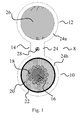
- Figure 1 shows a non-limiting embodiment of the present invention.
- the invention is directed to a cable 8 comprising a load bearing portion 12; a communications conveying portion 10; a connection portion 14 interconnecting the load bearing portion 12 with the communications conveying portion 10; and at least one ripcord 28 located at least partially within the connection portion 14 and extending longitudinally along the cable 8 to facilitate separation of the communications conveying portion 10 from the load bearing portion 12.
- the ripcord 28 may include any conventional ripcord made of, for example high-tensile strength glass, aramid, polyester, polymer, carbon or fiber filament. Further, the ripcord 28 may be color coded to distinguish the ripcord 28 from the connection portion 14. In addition, it should be understood that one or more ripcords can be used.
- the load bearing portion 12 may include a strength member 26 surrounded by a conventional plastic jacket (first jacket) 24a.
- the strength member 26 is also conventional and may be made of, for example, a fiber reinforced plastic rod or a metal, such as steel.
- the communications conveying portion 10 includes optical fibers and/or electrical wires (e.g., copper, copper alloy, aluminum and aluminum alloy). The invention is not limited to any particular design of the communications conveying portion 10.
- the communication conveying portion illustrated in Fig. 1 includes a reinforcing member 16 around which optical fibers 18 are arranged.
- a relatively soft layer 20 such as yarn or jell
- a tape 22 is wrapped around the yarn layer.
- a protective jacket (second jacket) 24b made of polyethylene or the like, is provided around the tape 22.
- connection portion 14 may be made of the same material as the first and second jackets 24a and 24b. More specifically, according to a preferred embodiment of the invention, a suitable plastic may be extruded around the strength member 26 and the optical fiber structure described above to form a cable having a figure-8 cross-section. In this manner, the first and second jackets 24a and 24b and the connection portion 14 will be unitary. Further, the ripcord 28 may be completely or partially embedded in the connecting portion during the extrusion process described above. For example, the ripcord may be arranged in a serpentine manner with the turns being exposed to the outside to allow easy access to the ripcord along the length of the cable.
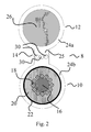
- FIG. 2 shows another non-limiting aspect of the present invention, wherein the connection portion 14 includes a weakened section 25, instead of a ripcord.
- the weakened section 25 may include at least one perforation 30 extending internally and longitudinally along the connection portion 14.
- the weakened section 25 with at least one perforation 30 acts to facilitate separation of the load bearing portion12 from the communications conveying portion 10.
- the weakened section 25 must be designed to insure that the connection portion 14 is sufficiently strong to support the communications conveying portion 10 on the load bearing portion 12 so that the two will not be inadvertently separated from one another in use.
- the purpose of providing the weakened section 25 is to allow a worker to cut the plastic so the communications conveying portion 10 can be separated from the load bearing portion 12 in the field.
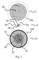
- connection portion 14 includes at least one ripcord 28 in conjunction with the weakened section 25, as described above.
- connection portion 14 includes at least one ripcord 28 in conjunction with an external weakened section 27.
- the weakened section 27 comprises at least one groove 32 extending along the outside of the connection portion 14 with ripcord 28 extending longitudinally along the cable adjacent to the groove or grooves 32.
- the cable of the invention including a ripcord allows for the doing away of or the minimizing of the need to access the cable with pocket knives, box cutters, razor blades, scalpels and other tools of dangerous implementation.
Landscapes
- Physics & Mathematics (AREA)
- General Physics & Mathematics (AREA)
- Optics & Photonics (AREA)
- Insulated Conductors (AREA)
- Light Guides In General And Applications Therefor (AREA)
- Electric Cable Installation (AREA)
Applications Claiming Priority (2)
| Application Number | Priority Date | Filing Date | Title |
|---|---|---|---|
| US319617 | 2002-12-16 | ||
| US10/319,617 US6861590B2 (en) | 2002-12-16 | 2002-12-16 | Strippable cable |
Publications (2)
| Publication Number | Publication Date |
|---|---|
| EP1431792A2 true EP1431792A2 (fr) | 2004-06-23 |
| EP1431792A3 EP1431792A3 (fr) | 2004-08-11 |
Family
ID=32392958
Family Applications (1)
| Application Number | Title | Priority Date | Filing Date |
|---|---|---|---|
| EP03027894A Ceased EP1431792A3 (fr) | 2002-12-16 | 2003-12-05 | Câble dissociable |
Country Status (2)
| Country | Link |
|---|---|
| US (1) | US6861590B2 (fr) |
| EP (1) | EP1431792A3 (fr) |
Cited By (1)
| Publication number | Priority date | Publication date | Assignee | Title |
|---|---|---|---|---|
| CN107942453A (zh) * | 2017-11-06 | 2018-04-20 | 杭州富通通信技术股份有限公司 | 蝶缆 |
Families Citing this family (13)
| Publication number | Priority date | Publication date | Assignee | Title |
|---|---|---|---|---|
| US7471862B2 (en) | 2002-12-19 | 2008-12-30 | Corning Cable Systems, Llc | Dry fiber optic cables and assemblies |
| US7066754B2 (en) * | 2004-07-29 | 2006-06-27 | Zih Corp. | Printer cable and associated strain relief collar for creating a ruggedized connection for an electrical terminal of a printer and associated methods therefor |
| JP5400035B2 (ja) * | 2007-05-08 | 2014-01-29 | コーロン インダストリーズ インク | 光ケーブル用リップコード及びその製造方法 |
| KR100847018B1 (ko) * | 2007-11-14 | 2008-07-17 | (주)티엠씨 | 시스 탈피용 립코드선을 구비한 선박용 케이블 |
| EP2483979B1 (fr) * | 2009-09-30 | 2017-04-05 | Orange | Dispositif d'installation de câble de transmission |
| US20110240334A1 (en) * | 2010-04-05 | 2011-10-06 | John Mezzalingua Associates, Inc. | Redundant webbing in conjoined cables |
| US10150252B2 (en) | 2014-09-23 | 2018-12-11 | Stryker Sustainability Solutions, Inc. | Method of recoupling components during reprocessing |
| EP3213134B1 (fr) | 2014-10-31 | 2022-08-10 | Prysmian S.p.A. | Câble d'alimentation/de télécommunication aérien autoporteur |
| US9335501B1 (en) | 2014-12-11 | 2016-05-10 | Google Inc. | Breakaway bundled interlocking drop fiber |
| US9329347B1 (en) | 2014-12-11 | 2016-05-03 | Google Inc. | Adjustable clamp sleeve for breakaway bundled interlocking drop fiber |
| CN105044870A (zh) * | 2015-09-17 | 2015-11-11 | 南京华信藤仓光通信有限公司 | 微束圆形缆及其制造方法 |
| RU169563U1 (ru) * | 2015-12-23 | 2017-03-23 | Общество с ограниченной ответственностью "АПЕРВИД" | Провод комбинированный |
| CN106098135A (zh) * | 2016-07-28 | 2016-11-09 | 江苏长峰电缆有限公司 | 一种自承式矿井用铝合金芯电缆 |
Citations (1)
| Publication number | Priority date | Publication date | Assignee | Title |
|---|---|---|---|---|
| US4815814A (en) * | 1986-09-02 | 1989-03-28 | Cooper Industries, Inc. | Under-carpet flat cable assembly and method of forming a turn in same |
Family Cites Families (13)
| Publication number | Priority date | Publication date | Assignee | Title |
|---|---|---|---|---|
| US2204782A (en) * | 1936-04-13 | 1940-06-18 | Belden Mfg Co | Method and apparatus for making electric conductor cord |
| US2628998A (en) | 1945-11-08 | 1953-02-17 | Gilbert Co A C | Splittable cable with visible conductors |
| US4467138A (en) | 1983-01-17 | 1984-08-21 | Gk Technologies, Inc. | Plural conductor communication wire |
| US4729628A (en) | 1986-11-14 | 1988-03-08 | Siecor Corporation | Fiber optic dropwire |
| US4763983A (en) | 1986-12-31 | 1988-08-16 | Sumitomo Electric Research Triangle, Inc. | Optical transmission cable with messenger |
| JP3077110B2 (ja) * | 1989-11-15 | 2000-08-14 | トヨクニ電線株式会社 | 通信用光ケーブル |
| US5180890A (en) | 1991-03-03 | 1993-01-19 | Independent Cable, Inc. | Communications transmission cable |
| US5442722A (en) | 1994-07-25 | 1995-08-15 | Siecor Corporation | Optical fiber ribbon with zip cord |
| KR100323143B1 (ko) * | 1998-03-25 | 2002-02-04 | 추후제출 | 광섬유 케이블 및 그 제조방법 |
| JP2000028877A (ja) * | 1998-07-09 | 2000-01-28 | Hitachi Cable Ltd | 光ファイバドロップ及びその製造方法 |
| US6563991B1 (en) * | 2000-06-13 | 2003-05-13 | Alcatel | Optical fiber cable for easy access to ripcords and having ripcord reliability |
| US6603908B2 (en) * | 2000-08-04 | 2003-08-05 | Alcatel | Buffer tube that results in easy access to and low attenuation of fibers disposed within buffer tube |
| US6734364B2 (en) * | 2001-02-23 | 2004-05-11 | Commscope Properties Llc | Connecting web for cable applications |
-
2002
- 2002-12-16 US US10/319,617 patent/US6861590B2/en not_active Expired - Fee Related
-
2003
- 2003-12-05 EP EP03027894A patent/EP1431792A3/fr not_active Ceased
Patent Citations (1)
| Publication number | Priority date | Publication date | Assignee | Title |
|---|---|---|---|---|
| US4815814A (en) * | 1986-09-02 | 1989-03-28 | Cooper Industries, Inc. | Under-carpet flat cable assembly and method of forming a turn in same |
Cited By (1)
| Publication number | Priority date | Publication date | Assignee | Title |
|---|---|---|---|---|
| CN107942453A (zh) * | 2017-11-06 | 2018-04-20 | 杭州富通通信技术股份有限公司 | 蝶缆 |
Also Published As
| Publication number | Publication date |
|---|---|
| US20040112629A1 (en) | 2004-06-17 |
| US6861590B2 (en) | 2005-03-01 |
| EP1431792A3 (fr) | 2004-08-11 |
Similar Documents
| Publication | Publication Date | Title |
|---|---|---|
| US6861590B2 (en) | Strippable cable | |
| US11215780B2 (en) | Optical fiber cable | |
| EP1168024B1 (fr) | Câble à fibres optiques avec cordes de déchirure | |
| EP1031862B1 (fr) | Procédé permettant d'accéder à des fibre optiques à mi-longeur d'un câble à fibres optiques | |
| US8798418B2 (en) | Optical cable with improved strippability | |
| US5982966A (en) | Asymmetric structure fiber optic cable | |
| KR20040035876A (ko) | 광섬유 케이블 | |
| WO1997041475A1 (fr) | Boite de distribution de cables-rubans de fibres optiques | |
| EP1220237B1 (fr) | Ensemble câbles comprenant des cordes de déchirure avec surlongueur et cordes de déchirure attachées à un ruban | |
| KR20230032891A (ko) | 광케이블 | |
| KR102735442B1 (ko) | 광케이블 | |
| US20070047884A1 (en) | Fiber optic cable with a concave surface | |
| JP2008076897A (ja) | 光ファイバケーブル | |
| US6987916B2 (en) | Fiber optic central tube cable with bundled support member | |
| CN213338130U (zh) | 一种扁平防鼠蚁引入光缆 | |
| EP0629889A1 (fr) | Câble optique | |
| SE503849C3 (sv) | Optokabelkonstruktion | |
| WO2022264400A1 (fr) | Câble à fibre optique | |
| JP2005128326A (ja) | 光ファイバケーブル | |
| JP6298479B2 (ja) | 光ファイバケーブル | |
| GB2187865A (en) | Optical wave guide ribbon cable | |
| US20260043978A1 (en) | Optical fiber cable | |
| JP4795270B2 (ja) | 光ファイバケーブル | |
| JP2009217195A (ja) | 光ファイバケーブル | |
| JP4128922B2 (ja) | 光ファイバケーブル |
Legal Events
| Date | Code | Title | Description |
|---|---|---|---|
| PUAI | Public reference made under article 153(3) epc to a published international application that has entered the european phase |
Free format text: ORIGINAL CODE: 0009012 |
|
| AK | Designated contracting states |
Kind code of ref document: A2 Designated state(s): AT BE BG CH CY CZ DE DK EE ES FI FR GB GR HU IE IT LI LU MC NL PT RO SE SI SK TR |
|
| AX | Request for extension of the european patent |
Extension state: AL LT LV MK |
|
| PUAL | Search report despatched |
Free format text: ORIGINAL CODE: 0009013 |
|
| AK | Designated contracting states |
Kind code of ref document: A3 Designated state(s): AT BE BG CH CY CZ DE DK EE ES FI FR GB GR HU IE IT LI LU MC NL PT RO SE SI SK TR |
|
| AX | Request for extension of the european patent |
Extension state: AL LT LV MK |
|
| RIC1 | Information provided on ipc code assigned before grant |
Ipc: 7H 01B 1/00 B Ipc: 7G 02B 6/44 A |
|
| 17P | Request for examination filed |
Effective date: 20050117 |
|
| AKX | Designation fees paid |
Designated state(s): AT BE BG CH CY CZ DE DK EE ES FI FR GB GR HU IE IT LI LU MC NL PT RO SE SI SK TR |
|
| 17Q | First examination report despatched |
Effective date: 20050603 |
|
| RAP1 | Party data changed (applicant data changed or rights of an application transferred) |
Owner name: DRAKA COMTEQ B.V. |
|
| STAA | Information on the status of an ep patent application or granted ep patent |
Free format text: STATUS: THE APPLICATION HAS BEEN REFUSED |
|
| 18R | Application refused |
Effective date: 20060609 |