EP1431974A2 - Disque optique, appareil d'enregistrement/lecture de disque optiqe et procédé d'évaluation de la qualité de signal d'un disque optique - Google Patents
Disque optique, appareil d'enregistrement/lecture de disque optiqe et procédé d'évaluation de la qualité de signal d'un disque optique Download PDFInfo
- Publication number
- EP1431974A2 EP1431974A2 EP03028985A EP03028985A EP1431974A2 EP 1431974 A2 EP1431974 A2 EP 1431974A2 EP 03028985 A EP03028985 A EP 03028985A EP 03028985 A EP03028985 A EP 03028985A EP 1431974 A2 EP1431974 A2 EP 1431974A2
- Authority
- EP
- European Patent Office
- Prior art keywords
- quality evaluation
- signal
- signal quality
- evaluation value
- optical disk
- Prior art date
- Legal status (The legal status is an assumption and is not a legal conclusion. Google has not performed a legal analysis and makes no representation as to the accuracy of the status listed.)
- Withdrawn
Links
- 230000003287 optical effect Effects 0.000 title claims abstract description 83
- 238000013441 quality evaluation Methods 0.000 title claims description 186
- 238000000034 method Methods 0.000 title claims description 35
- 230000004044 response Effects 0.000 claims abstract description 30
- 238000004364 calculation method Methods 0.000 claims description 19
- 238000004049 embossing Methods 0.000 claims description 9
- 238000010586 diagram Methods 0.000 description 13
- 238000005259 measurement Methods 0.000 description 13
- 238000011156 evaluation Methods 0.000 description 12
- 238000001514 detection method Methods 0.000 description 9
- 230000006870 function Effects 0.000 description 8
- 230000008569 process Effects 0.000 description 6
- 230000008859 change Effects 0.000 description 5
- 238000005070 sampling Methods 0.000 description 4
- 230000000875 corresponding effect Effects 0.000 description 3
- 239000000758 substrate Substances 0.000 description 3
- 238000005311 autocorrelation function Methods 0.000 description 2
- 238000012986 modification Methods 0.000 description 2
- 230000004048 modification Effects 0.000 description 2
- 229920000515 polycarbonate Polymers 0.000 description 2
- 239000004417 polycarbonate Substances 0.000 description 2
- 239000000523 sample Substances 0.000 description 2
- 238000007476 Maximum Likelihood Methods 0.000 description 1
- 238000012937 correction Methods 0.000 description 1
- 230000002596 correlated effect Effects 0.000 description 1
- 230000003111 delayed effect Effects 0.000 description 1
- 230000000694 effects Effects 0.000 description 1
- 230000001678 irradiating effect Effects 0.000 description 1
- 239000011295 pitch Substances 0.000 description 1
- 238000012545 processing Methods 0.000 description 1
Images






Classifications
-
- G—PHYSICS
- G11—INFORMATION STORAGE
- G11B—INFORMATION STORAGE BASED ON RELATIVE MOVEMENT BETWEEN RECORD CARRIER AND TRANSDUCER
- G11B20/00—Signal processing not specific to the method of recording or reproducing; Circuits therefor
- G11B20/10—Digital recording or reproducing
- G11B20/10009—Improvement or modification of read or write signals
-
- G—PHYSICS
- G11—INFORMATION STORAGE
- G11B—INFORMATION STORAGE BASED ON RELATIVE MOVEMENT BETWEEN RECORD CARRIER AND TRANSDUCER
- G11B20/00—Signal processing not specific to the method of recording or reproducing; Circuits therefor
- G11B20/10—Digital recording or reproducing
- G11B20/10009—Improvement or modification of read or write signals
- G11B20/10046—Improvement or modification of read or write signals filtering or equalising, e.g. setting the tap weights of an FIR filter
- G11B20/10055—Improvement or modification of read or write signals filtering or equalising, e.g. setting the tap weights of an FIR filter using partial response filtering when writing the signal to the medium or reading it therefrom
-
- G—PHYSICS
- G11—INFORMATION STORAGE
- G11B—INFORMATION STORAGE BASED ON RELATIVE MOVEMENT BETWEEN RECORD CARRIER AND TRANSDUCER
- G11B20/00—Signal processing not specific to the method of recording or reproducing; Circuits therefor
- G11B20/10—Digital recording or reproducing
- G11B20/10009—Improvement or modification of read or write signals
- G11B20/10046—Improvement or modification of read or write signals filtering or equalising, e.g. setting the tap weights of an FIR filter
- G11B20/10055—Improvement or modification of read or write signals filtering or equalising, e.g. setting the tap weights of an FIR filter using partial response filtering when writing the signal to the medium or reading it therefrom
- G11B20/1012—Improvement or modification of read or write signals filtering or equalising, e.g. setting the tap weights of an FIR filter using partial response filtering when writing the signal to the medium or reading it therefrom partial response PR(1,2,2,2,1)
-
- G—PHYSICS
- G11—INFORMATION STORAGE
- G11B—INFORMATION STORAGE BASED ON RELATIVE MOVEMENT BETWEEN RECORD CARRIER AND TRANSDUCER
- G11B20/00—Signal processing not specific to the method of recording or reproducing; Circuits therefor
- G11B20/10—Digital recording or reproducing
- G11B20/10009—Improvement or modification of read or write signals
- G11B20/10268—Improvement or modification of read or write signals bit detection or demodulation methods
- G11B20/10287—Improvement or modification of read or write signals bit detection or demodulation methods using probabilistic methods, e.g. maximum likelihood detectors
- G11B20/10296—Improvement or modification of read or write signals bit detection or demodulation methods using probabilistic methods, e.g. maximum likelihood detectors using the Viterbi algorithm
-
- G—PHYSICS
- G11—INFORMATION STORAGE
- G11B—INFORMATION STORAGE BASED ON RELATIVE MOVEMENT BETWEEN RECORD CARRIER AND TRANSDUCER
- G11B2220/00—Record carriers by type
- G11B2220/20—Disc-shaped record carriers
-
- G—PHYSICS
- G11—INFORMATION STORAGE
- G11B—INFORMATION STORAGE BASED ON RELATIVE MOVEMENT BETWEEN RECORD CARRIER AND TRANSDUCER
- G11B2220/00—Record carriers by type
- G11B2220/20—Disc-shaped record carriers
- G11B2220/21—Disc-shaped record carriers characterised in that the disc is of read-only, rewritable, or recordable type
- G11B2220/215—Recordable discs
- G11B2220/216—Rewritable discs
-
- G—PHYSICS
- G11—INFORMATION STORAGE
- G11B—INFORMATION STORAGE BASED ON RELATIVE MOVEMENT BETWEEN RECORD CARRIER AND TRANSDUCER
- G11B2220/00—Record carriers by type
- G11B2220/20—Disc-shaped record carriers
- G11B2220/21—Disc-shaped record carriers characterised in that the disc is of read-only, rewritable, or recordable type
- G11B2220/215—Recordable discs
- G11B2220/218—Write-once discs
Definitions
- the present invention relates to an optical disk, an optical disk recording/reproduction apparatus, and a method for evaluating optical data of the optical disk.
- Optical disks are classified into two types: read-only optical disks on which data are recorded in advance and optical disks on which data can be recorded.
- an exposure process called a mastering process is performed to form embossments (physically raised and recessed conditions) on the optical disk.
- embossments physically raised and recessed conditions
- the optical disk is irradiated with a focused laser beam to change a specific physical characteristic of a recording film.
- the jitter characteristic is usually represented as the time-transient fluctuation of an edge position that is obtained by slicing a reproduction signal at a specific reference potential.
- the PRML Partial-Response Maximum-Likelihood
- PR equalization is defined by the amplitude for each data cycle (clock). For example, for PR(abc), the amplitude at time 0 is a, the amplitude at time T is b, the amplitude at time 2T is c and the amplitude at all other times is 0. The total number of components having an amplitude other than 0 is called a constraint length.
- the PRML instead of detecting the edge position to decode data, the value obtained by sampling a reproduced waveform each clock cycle is employed to obtain data through the Viterbi decoding. Therefore, it is difficult to estimate the detection function of the PRML based only on the time-transient fluctuation data for the edge position.
- one object of the present invention to provide a signal quality evaluation index to be used instead of jitter when the density is too high to measure the jitter, and a reference value therefor.
- a quality evaluation method for a reproduced equalized signal obtained by reproducing and equalizing a signal recorded on an optical disk by using embossing, or by using an optical data recording apparatus.
- This method of the present invention comprises the steps of:
- a signal quality evaluation method comprises the steps of:
- a signal quality evaluation method comprises the steps of:
- the quality of the signal recorded on the optical disk is evaluated by examining a first signal quality evaluation value Si, a second signal quality evaluation value S 2 and a third signal quality evaluation value S 3 that are represented by the following equations (3), (4) and (5).
- binary data obtained by a Viterbi decoder are used for a data string used to generate a target signal for calculating the equalization error. Further, the signal quality is evaluated by using 10 4 , or more, equalization errors.
- an optical disk is provided on which data are recorded under a condition wherein the signal quality evaluation value S, or the first signal quality evaluation value S 1 , the second signal quality evaluation value S 2 and the third signal quality evaluation value S 3 , are equal to or greater than 12, and preferably are equal to or greater than 15.
- an optical disk recording/reproduction or reproduction apparatus performs data recording or data reproduction under a condition wherein the signal quality evaluation value S, or the first signal quality evaluation value S 1 , the second signal quality evaluation value S 2 and the third signal quality evaluation value S 3 , are equal to or greater than 12, and preferably are equal to or greater than 15.
- an optical disk recording/reproduction or reproduction apparatus comprises:
- an optical disk recording/reproduction or reproduction apparatus comprises:
- Viterbi decoding For the PRML, an algorithm called Viterbi decoding is employed to discriminate data. According to the Viterbi decoding, the square of a difference between the value of a reproduction signal and a predetermined level defined by a partial response is calculated, the square sum is obtained along each path, and a path providing the smallest square sum is selected to decode the data.
- D denotes a time delay operator using a clock time as a unit
- h k denotes a predetermined partial response characteristic.
- the partial response characteristic is represented as PR( h0 , h1 , h2 , h3 , ...) generally by using the element of h k that is not 0.
- a combination of 1 and 0, or a combination of 1 and -1 is used, and In this invention, the combination of 1 and - 1 is used. Since the amplitude of a waveform obtained when the combination of 1 and 0 is used is 1/2 the amplitude of a waveform when the combination of 1 and -1 is used, the numerators for the evaluation values S 1 to S 3 defined by equations 10 to 12 need only be set to 1/4. That is, only 3.5 or 3 need be used.
- the Euclid distance d between the paths can be calculated for each set of tap coefficients ⁇ i .
- restriction ⁇ i ⁇ i+1 ⁇ -1 need only be provided for the set of tap coefficients ⁇ i .
- (x, 1, -1, y), for example, can be used as the data string b k that satisfies ⁇ i ⁇ i+1 , and (x, 01, 1, y) can be used as the data string c k .
- the probability whereat a detection error will occur for the Euclid distance d between the two paths is equivalent to the probability whereat ⁇ (y k - ⁇ b k-i h i ) 2 will be greater than ⁇ (y k - ⁇ c k-i h l ) 2 due to noise.
- y k - ⁇ b k-i h i is an equalization error.
- the difference between ⁇ (y k - ⁇ b k-i h i ) 2 and ⁇ (y k - ⁇ c k-i h i ) 2 may be observed using the following method.
- An error vector is defined by regarding, as the elements of a vector, the coefficients of the polynomial defined by using the difference between B(D)H(D) and C(D)H(D), and the equalization error is projected onto the error vector.
- the probability of the occurrence of a detection error is defined as the probability whereat the magnitude of the noise (the variance of the noise) projected onto the error vector is greater than half the Euclid distance between the paths.
- this data string can be used as a reference data string, and when such data have not yet been obtained, probable binary data that are obtained by a Viterbi decoder can be used.
- the probability whereat the data string b k will be erroneously regarded as the data string c k for PR(1221) equals the probability whereat the magnitude of the equalization error projected onto 2 x (1,2,2,1) is greater than half the Euclid distance (in this case, 2 x (1 + 2 x 2 + 2 x 2 + 1) 1/2 ) between the two paths. Since the projection of the equalization error onto the error vector is represented by the following equation (6), the variance CN of the noise projected onto the error vector is represented by the following equation (7).
- v k (y k - ⁇ a k-i h i ) is defined as an equalization error wherein y k denotes the value of a signal reproduced and equalized for each clock cycle, a k denotes a predetermined data string for generation of a target signal and h k denotes a predetermined partial response, while D is defined as a time delay operator using a clock time as a unit.
- the probability that a detection error will occur can be obtained, i.e., the quality of a reproduced signal can be evaluated.
- the data strings b k and c k have been used as an example combination of data strings that tend to be erroneously regarded.
- specific data strings need not always be selected to obtain an equalization error. That is, for the calculation of the equalization error variance, a time corresponding to the data string b k need not be extracted from the data string a k used for the generation of a target signal. Instead, the equalization error obtained for each clock time can be used to calculate the variance.
- the variance of the noise may be calculated by using only a specific data string b k ; however, when the variance of the equalization errors is calculated without selecting a pattern, the configuration of the circuit is simplified.
- Fig. 2 is a diagram showing an example of functional block for calculating a signal quality evaluation value S.
- An A/D converter 10 performs sampling for a reproduced signal having a constant frequency, and an equalizer 11 that includes a PLL (phase look loop) circuit obtains equalized reproduced waveform data each clock cycle.
- PLL phase look loop
- the reproduced waveform is equalized so that it is as similar as possible to a target waveform based on a PR waveform.
- a signal quality evaluation unit 12 calculates the signal quality evaluation value S by using the received, equalized reproduced waveform, and evaluates the quality of the reproduced waveform.
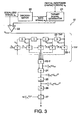
- Fig. 3 is a detailed diagram showing the signal quality evaluation unit 12 in Fig. 2.
- a reference PR waveform is denoted by h 1
- binary data obtained by a discriminator 20 (typically, a Viterbi decoder) is denoted by a k
- a target signal generator 21 generates a target signal R k based on the following equation (11).
- a comparator 22 calculates an equalization error v k that is the difference between a signal y k , reproduced (equalized) for each clock cycle, and the target signal R k .
- the equalization error v k is delayed for each clock cycle by a plurality of taps 23, and the results are added by an adder 23-2 through a plurality of coefficient multipliers 23-1 each of which is for multiplying by tap coefficient ⁇ i .
- the plurality of taps, namely, unit delay elements 23, the plurality of coefficient multipliers 23-1 and one adder 23-2 constitute a transversal filter TRF.
- the tap coefficient ⁇ i is a coefficient of the N(D) described above.
- a corresponding signal quality evaluation value S is defined as a j-th signal quality evaluation value S j
- a total number m of the taps 23(D) in Fig. 3 is changed, depending on j.
- a multiplier 24 calculates the square of equalization error ⁇ l x v k+1 , which is obtained through the plurality of tap coefficient multipliers 23-1 and the adder 23-2, and an adder 25 multiplies the resultant square by the total number N of equalization error samples. As a result, a value is obtained that is proportional to the variation of the noise projected onto the error vector. When this value is divided by N and ⁇ i 2 , a variation value is obtained, and since N and ⁇ i 2 are constants, these are employed as the coefficients by a multiplier 27.
- a divider 26 calculates the reciprocal of the obtained value, namely, the output of the adder 25, and the multiplier 27 calculates a product (N ⁇ i 2 ) x ⁇ i 2 .
- the signal quality evaluation value S is obtained.
- (N + m) reproduced waveform samples are required; however, since m is at most 20 while N is equal to or greater than 10 4 , in this invention, N is consistently employed as the number of samples. The required total number of samples will be explained later.
- a bit error rate (bER) and the signal quality evaluation value S is examined by a read-only optical disk (ROM disk), provided in advance by using embossing to record a pit data string on a polycarbonate substrate that is 0.6 mm thick.
- the pit string was formed on the substrate as random data that was modulated based on the (1-7) modulation method, and the length of a 2T pit, which is the shortest, was 0.2 ⁇ m, while in the radial direction, the interval for the pits was 0.4 ⁇ m.
- An optical head having a wavelength of 405 nm and a numerical aperture (NA) of 0.65 for an object lens was employed to reproduce data recorded on the ROM disk at a linear speed of 6.6 m/s and at a reproduction power of 0.5 mW (in this case, a clock cycle T is 15.15 ns). Then, the reproduced waveform was equaled to PR(12221) to measure the bit error rate bER and the signal quality evaluation value S.
- bit error rate bER the original data recorded on the optical disk were compared with the binary data obtained through Viterbi decoding; and to measure the signal equality evaluation value S, 10 5 values of reproduced waveform obtained for each T after PR equalization and the binary data obtained by Viterbi decoding were employed.
- the (1-7) modulated codes are codes having a limitation d ⁇ 1, and relative to PR(12221), the Euclid distance is reduced in accordance with the tap coefficients ⁇ j shown in Table 1.
- a set of tap coefficients ⁇ j discriminated by pattern 1 in Table 1, i.e., (1 2 2 2 1), is an error vector that is determined by two data strings that tend to be erroneously discriminated in Viterbi detection, e.g., b k : (1 1 1 1 1 -1 -1 ...) and c k : (-1 1 1 1 -1 -1 ...), and partial response characteristic (1 2 2 2 1).
- the number of 0s inserted between (1, 2, 1) and (-1, -2, -1) and the upper limit number of 0s inserted between (1, 2, 1) and (1, 2, 1) are determined by the upper limit repetitions of the mark/space for 2T (the upper limit repetitions of a data string of +1 +1 -1 -1, e.g., -1 -1 -1 +1 +1 -1 -1 -1 is counted as one repetition and -1 -1 -1 +1 +1 -1 +1 +1 +1 +1 +1 is counted as two repetitions).
- the signal quality evaluation value S need only be calculated while taking into account the pattern up to the upper limit.
- Table 1 the tap coefficients ⁇ i , up to a maximum of five repetitions for 2T, are shown, and in this embodiment, 2T was also repeated five times at the maximum for the pattern that was recorded, using embossing, on the optical data recording medium.
- a pattern having a polarity opposite to that of the pattern shown in Table 1 may be employed; however, since the obtained signal quality evaluation value S is the same, only a pattern having a predetermined polarity must be taken into account (either polarity can be determined, but there is no need to evaluate both).
- fourteen taps were fixed, which corresponds to the number of taps required for the catenation of a sixth signal quality evaluation value S 6 ; and to calculate, for example, the first signal quality evaluation value S 1 for pattern 1, the fifth and following tap coefficients were regarded as being 0.
- Table 2 shows the signal equality evaluation values S measured while changing a tilt.
- the j-th signal quality evaluation value S j represents the one obtained for pattern j in Table 1.
- Fig. 4 is a graph showing the relationship between the smallest signal quality evaluation value S under each tilt condition and the bit error rate bER. As is apparent from Fig. 4, an obvious correlation is established between the signal quality evaluation value S and the bit error rate bER.
- the original data recorded in advance on the optical disk have been employed to measure the bit rate error bER. Since it is usually difficult for the original data recorded on a read-only disk to be accurately known, the measurement of the bit error rate bER is almost disabled, and it is, therefore, very difficult for the conduct of the reproduction to be adjusted by using the bit error rate bER as an index. However, even in such a case, as is explained in this embodiment, when the reproduction condition is adjusted by using the signal quality evaluation value S as an index, data recorded on the optical disk can be stably reproduced.
- bit error rate bER and the signal quality evaluation value S was examined by using a phase change optical disk formed on a 0.6 mm thick polycarbonate substrate, wherein the pitches of guide grooves were 0.68 ⁇ m.
- the PR equalization was PR(12221).
- the random data were overwritten twenty times, using a recording power of 6 mW and an erasing power of 2.5 mW, and then, the signal quality evaluation value S and the bit error rate bER were measured while the focus offset value was changed.
- the recording was performed for up to a maximum five repetitions of 2T, and the first to sixth signal quality evaluation values S 1 to S 6 were calculated by employing 10 5 values of reproduced waveforms obtained for each clock after the PR equalization and the binary data obtained by Viterbi decoding.
- Fig. 5 is a graph showing the relationship between the smallest signal quality evaluation value S and the bit error rate bER under each defocusing condition. As is apparent from Fig. 5 as well as from Fig. 4, there is an obvious correlation between the signal quality evaluation value S and the bit error rate bER, and this correlation is the same as that in Fig. 1. It was also confirmed that, when the smallest signal quality evaluation value S was equal to or greater than 12, the bit error rate bER was equal to or greater than 3 x 10 -4 .
- the bit error rate bER 3 x 10 -4 is an index value with which error correction is enabled by using an ECC (error correcting code), such as Reed-Solomon code, to obtain a signal at a level that presents no problem when put to practical use. Therefore, when the reproduction condition (a tilt or defocusing) is adjusted to obtain the smallest signal quality evaluation value of 12 or greater, the optical disk reproduction apparatus can be stably operated.
- ECC error correcting code
- the bit error rate bER be set lower, by about one digit. than the threshold value for the stable operation of the apparatus.
- the signal quality evaluation value S need only be equal to or greater than 15. Therefore, it is preferable that the reproduction condition be adjusted to satisfy a condition wherein the smallest signal quality evaluation value S is equal to or greater than 12, and more preferably, is equal to or greater than 15.
- the recording/reproduction condition can be adjusted based on the signal quality evaluation value S.
- the smallest signal quality evaluation value S is either the first signal quality evaluation value S 1 , the second signal quality evaluation value S 2 or the third signal quality evaluation value S 3 .
- the adjustment of the recording/reproduction condition can be simplified by examining these three signal quality evaluation values S.
- Fig. 9 is a diagram showing an example of an optical data recording/reproduction apparatus that includes a function for adjusting a recording condition or a reproduction condition based on the signal quality evaluation value S.
- the quality of a reproduced signal that is read by an optical head 13 is determined based on the signal quality evaluation value S obtained by a signal quality evaluation unit 12. While the recording/reproduction condition, e.g., a tilt or defocusing or recording power, is changed by a recording/reproduction condition adjustment unit 14, the signal quality evaluation value S is calculated for each condition, and the condition whereunder the signal quality evaluation value S reaches the maximum, or the recording/reproduction condition whereunder the signal quality evaluation value S reaches a constant value (e.g., is equal to or greater than the 12 described above), is found. As a result, the data recording/reproduction operation can be performed under a stabilized condition.
- the recording/reproduction condition e.g., a tilt or defocusing or recording power
- the first signal quality evaluation value S 1 for the first or the second embodiment can also be represented by the following equation (12):
- the second signal quality evaluation value S 2 and the third signal quality evaluation value S 3 can also be represented by the following equations (13) and (14):
- R i corresponds to the auto-correlation of an equalization error, and it is understood that when the values other than R 0 are 0, the characteristic of the equalization error is white.
- the same calculation can be performed for the signal quality evaluation values S other than the first, the second and the third signal quality evaluation values S 1 , S 2 and S 3 in Table 1, or for a set of arbitrary tap coefficients ⁇ i , so that the signal quality evaluation value S can be represented as the auto-correlation function.
- the number of the multipliers 61 in Fig. 6 is varied, depending on the j-th signal quality evaluation value S i to be calculated, and nine multipliers are required to obtain the third signal quality evaluation value S 3 .
- the number of multipliers 61 in Fig. 6 is varied, depending on the j-th signal quality evaluation value S i to be calculated, and nine multipliers are required to obtain the third signal quality evaluation value S 3 .
- 23-4 is a multiplier and 23-5 is a mean average calculation unit.
- the mean average calculation units 23-5 may be implemented by, for example, low-pass filters or digital operation units.
- the acquisition of the mean average may not be performed (no division is performed using the total number N of samples). In this case, simply, only the sum described above must be obtained, and only the numerator of the signal quality evaluation value S (12 or 14 in this embodiment) must be multiplied by N.
- the measurement process as performed for the first and the second embodiment was conducted with the configuration in Fig. 6, and it was confirmed that the same signal quality evaluation value S was acquired as was obtained in the first and the second embodiments.
- predetermined addition and multiplication are preformed for the auto-correlation of an equalization error v m for each clock time, and the first, second and third signal quality evaluation values S 1 , S 2 and S 3 are obtained using the following equations (15) to (17). Then, the smallest value is examined to evaluate the quality of the reproduced, equalized signal.
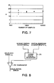
- Fig. 7 is a graph showing the smallest signal evaluation value S (the first signal quality evaluation value S 1 in this embodiment) that was obtained by several measurement operations performed under each condition for which the total number of samples was changed. As is shown in Fig.
- the measurement it is convenient for the measurement to be conducted for each ECC block unit, at the least. For example, for 64 Kbit ECC blocks, samples for 786432 bits are employed, and this is satisfactory for the accurate measurement of the signal quality evaluation value S.
- the relationship between the number of sample reproduced waveforms and the signal quality evaluation value S was examined by using the phase change optical disk described in the second embodiment.
- the optical head and the measurement conditions, such as the linear speed and the PR equalization, were the same as those for the second embodiment, except for the total number of samples. It should be noted that in this embodiment the measurement was performed with a focus offset of 0. While the total number of samples was changed, the signal quality evaluation value S (in this case, the third signal quality evaluation value S 3 , which is the smallest of all) was measured by performing several measurements under each condition. As a result, as well as in the fifth embodiment, it was confirmed that the signal quality evaluation values S were distributed across a wide range when the number of samples was smaller than 10000. Therefore, to adjust the reproduction condition using the signal quality evaluation value S as an index, at least 10000 samples are required.
- Fig. 8 is a diagram showing an example functional block for evaluating the quality of a signal when recorded data are known. While to calculate an equalization error only the functional block is shown in Fig. 8, the configuration in Fig. 3 or 6 can be employed for the signal quality evaluation operation after the equalization error has been obtained.
- the signal quality evaluation value S is to be measured for data that are recorded by a recording/reproduction apparatus, instead of employing data output by a Viterbi decoder, the recorded data that are already known can be used as reference data. Further, for a reproduction apparatus, since the same data are always recorded at a predetermined location on an optical disk, when data are already known, the data are recorded in the internal memory of the reproduction apparatus so that they can be employed as reference data for evaluating the signal quality evaluation value S.
- the signal quality evaluation value S must only be measured for patterns shown in Table 4. Further, to simplify the process, the signal quality evaluation values S may be measured only for patterns 1 and 2.
- the set of data strings that provides 14 is a set of data strings that differ by only one bit, such as (x 1 1 1 1 -1 -1 x) and (x 1 1 -1 -1 -1 x) (x is either 1 or -1).
- equation (19) is employed for the equalization error for the data string (x 1 1 1 1 -1 -1 x) and the equalization error for the data string (x 1 1 1 -1 -1 x)
- the first signal quality evaluation value S 1 can be obtained.
- the data strings used for calculating the first signal quality evaluation value S 1 are not limited to these two strings, and all other data strings that differ by only one bit can be employed.
- a set of data strings wherein two bits located at a distance represented by the time 2T are different is an example set that provides ⁇ i 2 and that is used to calculate the second signal quality evaluation value S 2 .
- equation (20) can be employed for the equalization error for data string (x x 1 1 1 -1 -1 1 x) and the equalization error for data string (x x 1 1 -1 -1 1 1 x), so that the second signal quality evaluation value S 2 can be calculated.
- the data strings used for calculating the second signal quality evaluation value S 2 are not limited to these two, and all other data strings wherein two bits located at a distance represented by the time 2T are different can be employed.
- a set of data strings wherein two bits located at a distance represented by the time 2T are continuously different is an example set used to calculate the third signal quality evaluation value S 3 .
- the data strings used to calculate the first, the second and the third signal quality evaluation values S 1 , S 2 and S 3 are recorded in advance on the determination unit 71, and only when these data strings have been received by the determination unit 71 is the calculation performed for the signal quality evaluation value S.
- Fig. 10 is a diagram showing an example wherein a signal is transmitted by a target signal generator 21 to the determination unit 71. Instead, however, a signal output by a discriminator (a Viterbi decoder) 20 may be transmitted to the determination unit 71.
- a discriminator a Viterbi decoder
- Fig. 9 is a diagram showing an example optical data recording/reproduction apparatus that comprises the recording/reproduction condition adjustment unit 14, which has a function for adjusting one or both of a recording condition and a reproduction condition based on the signal quality evaluation value S obtained by the signal quality evaluation unit 12.
- the optical head 13 When the recording/reproduction condition adjustment unit 14 adjusts a recording/reproduction condition, such as a tilt, focus or a recording power, the optical head 13 reads a signal based on the recording/reproduction condition adjusted by the recording/reproduction condition adjustment unit 14. The signal quality evaluation unit 14 then calculates the signal quality evaluation value S for the signal read by the optical head 13. Thereafter, the recording/reproduction condition adjustment unit 14 receives the obtained signal quality evaluation value S.
- a recording/reproduction condition such as a tilt, focus or a recording power
- the recording/reproduction condition adjustment unit 14 searches for the optimal recording/reproduction condition, or for one that, at the least, is at a specific satisfactory level, so that the signal quality evaluation value S obtained is the optimum or equals a predetermined value (e.g., is equal to or greater than the 12 described above).
- the optical head 13 performs data recording/reproduction for the optical disk based on the optimum or a satisfactory recording/reproduction condition that is determined by the recording/reproduction condition adjustment unit 14.
- the recording/reproduction condition adjustment unit 14 can determine the optimum or a preferable recording condition or reproduction condition based on, as an index, the signal quality evaluation value S that is obtained by the signal quality evaluation unit 12, the condition under which data recording/reproduction is performed by the optical data recording/reproduction apparatus can be stabilized.
- the quality of a signal recorded on an optical data recording medium can be evaluated at a high recording density under which the evaluation of the signal quality using jitter is disabled. Further, the recording/reproduction condition can be optimized by using, as an index, the signal quality defined in the invention.
Landscapes
- Engineering & Computer Science (AREA)
- Signal Processing (AREA)
- Physics & Mathematics (AREA)
- Probability & Statistics with Applications (AREA)
- Optical Recording Or Reproduction (AREA)
- Error Detection And Correction (AREA)
- Signal Processing For Digital Recording And Reproducing (AREA)
Applications Claiming Priority (4)
| Application Number | Priority Date | Filing Date | Title |
|---|---|---|---|
| JP2002365772 | 2002-12-17 | ||
| JP2002365772 | 2002-12-17 | ||
| JP2003386726 | 2003-11-17 | ||
| JP2003386726A JP4102738B2 (ja) | 2002-12-17 | 2003-11-17 | 光ディスクの信号品質評価方法、品質評価装置、および、光ディスク装置 |
Publications (2)
| Publication Number | Publication Date |
|---|---|
| EP1431974A2 true EP1431974A2 (fr) | 2004-06-23 |
| EP1431974A3 EP1431974A3 (fr) | 2011-10-19 |
Family
ID=32396328
Family Applications (1)
| Application Number | Title | Priority Date | Filing Date |
|---|---|---|---|
| EP03028985A Withdrawn EP1431974A3 (fr) | 2002-12-17 | 2003-12-17 | Disque optique, appareil d'enregistrement/lecture de disque optiqe et procédé d'évaluation de la qualité de signal d'un disque optique |
Country Status (4)
| Country | Link |
|---|---|
| US (1) | US7184381B2 (fr) |
| EP (1) | EP1431974A3 (fr) |
| JP (1) | JP4102738B2 (fr) |
| CN (1) | CN100419891C (fr) |
Families Citing this family (27)
| Publication number | Priority date | Publication date | Assignee | Title |
|---|---|---|---|---|
| JP3967691B2 (ja) * | 2003-03-31 | 2007-08-29 | 株式会社東芝 | 情報記憶媒体と情報再生装置と情報記録再生装置 |
| JP2004327013A (ja) * | 2003-04-11 | 2004-11-18 | Nec Corp | 光ディスク媒体および光ディスク装置 |
| JP4423670B2 (ja) * | 2003-11-27 | 2010-03-03 | 日本電気株式会社 | 情報記録媒体の再生方法および情報記録または再生を行う装置 |
| JP4377677B2 (ja) * | 2003-12-25 | 2009-12-02 | 株式会社東芝 | ディスク装置及びディスク再生方法 |
| US8452316B2 (en) * | 2004-06-18 | 2013-05-28 | Qualcomm Incorporated | Power control for a wireless communication system utilizing orthogonal multiplexing |
| US7594151B2 (en) * | 2004-06-18 | 2009-09-22 | Qualcomm, Incorporated | Reverse link power control in an orthogonal system |
| US7197692B2 (en) | 2004-06-18 | 2007-03-27 | Qualcomm Incorporated | Robust erasure detection and erasure-rate-based closed loop power control |
| US8942639B2 (en) * | 2005-03-15 | 2015-01-27 | Qualcomm Incorporated | Interference control in a wireless communication system |
| US8848574B2 (en) | 2005-03-15 | 2014-09-30 | Qualcomm Incorporated | Interference control in a wireless communication system |
| WO2006101007A1 (fr) * | 2005-03-18 | 2006-09-28 | Nec Corporation | Procede pour ajuster l'inclinaison d'un support d'enregistrement d'informations et dispositif de reproduction et d'enregistrement d'informations pour ledit procede |
| JP4473768B2 (ja) * | 2005-04-14 | 2010-06-02 | 株式会社東芝 | 情報記憶媒体、再生方法及び記録方法 |
| JP2006289877A (ja) * | 2005-04-14 | 2006-10-26 | Toshiba Corp | 情報記憶媒体、再生方法及び記録方法 |
| WO2007034771A1 (fr) | 2005-09-21 | 2007-03-29 | Nec Corporation | Procédé de réglage de l'inclinaison et dispositif d'enregistrement/reproduction d'informations utilisant celui-ci |
| KR101097021B1 (ko) * | 2005-10-27 | 2011-12-20 | 콸콤 인코포레이티드 | 무선 통신 시스템에서 역방향 링크 로딩을 추정하기 위한 방법 및 장치 |
| KR20070082504A (ko) * | 2006-02-15 | 2007-08-21 | 삼성전자주식회사 | 신호 품질 평가 장치 및 방법과 광 디스크 구동기 |
| US20070263506A1 (en) * | 2006-05-10 | 2007-11-15 | Clarestow Corporation | Method and system for detecting of errors on optical storage media |
| US8442572B2 (en) * | 2006-09-08 | 2013-05-14 | Qualcomm Incorporated | Method and apparatus for adjustments for delta-based power control in wireless communication systems |
| US8670777B2 (en) | 2006-09-08 | 2014-03-11 | Qualcomm Incorporated | Method and apparatus for fast other sector interference (OSI) adjustment |
| EP2043102A4 (fr) * | 2006-12-28 | 2011-07-06 | Panasonic Corp | Procede d'evaluation de support d'enregistrement d'informations, support d'enregistrement d'informations, procede de fabrication de support d'enregistrement d'informations, procede de traitement de signal et dispositif de commande d'acces |
| JP5003284B2 (ja) * | 2007-05-24 | 2012-08-15 | 日本電気株式会社 | 信号品質測定装置及び情報再生装置 |
| JPWO2009041598A1 (ja) * | 2007-09-26 | 2011-01-27 | 日本電気株式会社 | 信号品質評価装置、方法、及び、情報記録再生装置 |
| KR20100115699A (ko) * | 2008-02-28 | 2010-10-28 | 파나소닉 주식회사 | 신호 평가 방법 및 신호 평가 장치 |
| JP5391081B2 (ja) | 2008-07-01 | 2014-01-15 | パナソニック株式会社 | 再生信号評価方法、再生信号評価装置及びこれを備えた光ディスク装置 |
| CA2707185A1 (fr) | 2008-10-02 | 2010-04-08 | Panasonic Corporation | Procede d'evaluation d'un signal reproduit, support d'enregistrement d'0nformations, dispositif de reproduction, et dispositif d'enregistrement |
| US20100085851A1 (en) * | 2008-10-02 | 2010-04-08 | Panasonic Corporation | Method and apparatus for evaluating information recording medium |
| US8179760B2 (en) | 2008-10-02 | 2012-05-15 | Panasonic Corporation | Reproduction signal evaluation method, information recording medium, reproduction apparatus and recording apparatus |
| BRPI1000035A2 (pt) | 2009-02-03 | 2016-09-27 | Panasonic Corp | método de avaliação de sinal de reprodução, unidade de avaliação de sinal de reprodução e dispositivo de disco ótico adotando o mesmo |
Family Cites Families (5)
| Publication number | Priority date | Publication date | Assignee | Title |
|---|---|---|---|---|
| JP3432003B2 (ja) * | 1994-07-06 | 2003-07-28 | キヤノン株式会社 | 情報再生装置及び情報記録再生装置 |
| JP2830803B2 (ja) * | 1995-11-17 | 1998-12-02 | 日本電気株式会社 | 位相検出器及びこれを用いた磁気ディスク装置 |
| KR100580166B1 (ko) * | 1999-11-04 | 2006-05-15 | 삼성전자주식회사 | 등화기의 필터 계수를 조절하여 재생 성능을 높이는 장치및 방법 |
| JP2001307334A (ja) * | 2000-04-21 | 2001-11-02 | Toshiba Corp | 情報記憶媒体、情報記録方法、及び情報再生方法 |
| JP3855702B2 (ja) * | 2000-12-15 | 2006-12-13 | ソニー株式会社 | 再生信号評価装置および方法、再生装置および方法、ならびに、記録装置および方法 |
-
2003
- 2003-11-17 JP JP2003386726A patent/JP4102738B2/ja not_active Expired - Lifetime
- 2003-12-17 EP EP03028985A patent/EP1431974A3/fr not_active Withdrawn
- 2003-12-17 US US10/736,572 patent/US7184381B2/en not_active Expired - Lifetime
- 2003-12-17 CN CNB2003101249066A patent/CN100419891C/zh not_active Expired - Lifetime
Also Published As
| Publication number | Publication date |
|---|---|
| CN1549266A (zh) | 2004-11-24 |
| CN100419891C (zh) | 2008-09-17 |
| JP2004213862A (ja) | 2004-07-29 |
| US7184381B2 (en) | 2007-02-27 |
| US20040208101A1 (en) | 2004-10-21 |
| JP4102738B2 (ja) | 2008-06-18 |
| EP1431974A3 (fr) | 2011-10-19 |
Similar Documents
| Publication | Publication Date | Title |
|---|---|---|
| EP1431974A2 (fr) | Disque optique, appareil d'enregistrement/lecture de disque optiqe et procédé d'évaluation de la qualité de signal d'un disque optique | |
| EP1467357B1 (fr) | Support d'enregistrement optique avec une zone d'enregistrement à basse densité pour des informations de système | |
| US7522504B2 (en) | Signal quality evaluation method, information recording/reproducing system, and recording compensation method | |
| US8270542B2 (en) | Method for evaluating quality of read signal and apparatus for reading information | |
| JP3926688B2 (ja) | 再生信号品質評価方法および情報再生装置 | |
| JP3857685B2 (ja) | 信号評価方法と情報記録再生装置と情報再生装置及び情報媒体 | |
| KR20110044831A (ko) | 재생 신호 평가 방법, 재생 신호 평가 장치 및 이것을 구비한 광디스크 장치 | |
| EP1921621B1 (fr) | Méthode d'égalisation d'un signal reproduit pour des supports d'information optique | |
| US7428203B2 (en) | Signal evaluation method, information recording/reproducing apparatus, information reproducing apparatus, and information recording medium | |
| EP2249343B1 (fr) | Procédé d'ajustement pour enregistrer les conditions et dispositif de disque optique | |
| US7106677B2 (en) | Reproduction signal evaluation method | |
| JPWO2009041598A1 (ja) | 信号品質評価装置、方法、及び、情報記録再生装置 | |
| WO2005073963A1 (fr) | Procédé de d'ajustement de position et dispositif d'ajustement de position servo | |
| JP4103320B2 (ja) | 情報再生装置及び再生方法 | |
| CN1983429A (zh) | 光盘、光盘记录/再生装置以及光盘的信号品质评价方法 | |
| JP2007265618A (ja) | 光学情報媒体の再生信号等化方法及び光学情報記録再生装置 |
Legal Events
| Date | Code | Title | Description |
|---|---|---|---|
| PUAI | Public reference made under article 153(3) epc to a published international application that has entered the european phase |
Free format text: ORIGINAL CODE: 0009012 |
|
| AK | Designated contracting states |
Kind code of ref document: A2 Designated state(s): AT BE BG CH CY CZ DE DK EE ES FI FR GB GR HU IE IT LI LU MC NL PT RO SE SI SK TR |
|
| AX | Request for extension of the european patent |
Extension state: AL LT LV MK |
|
| PUAL | Search report despatched |
Free format text: ORIGINAL CODE: 0009013 |
|
| AK | Designated contracting states |
Kind code of ref document: A3 Designated state(s): AT BE BG CH CY CZ DE DK EE ES FI FR GB GR HU IE IT LI LU MC NL PT RO SE SI SK TR |
|
| AX | Request for extension of the european patent |
Extension state: AL LT LV MK |
|
| RIC1 | Information provided on ipc code assigned before grant |
Ipc: G11B 7/004 20060101ALI20110914BHEP Ipc: G11B 20/10 20060101AFI20110914BHEP |
|
| STAA | Information on the status of an ep patent application or granted ep patent |
Free format text: STATUS: THE APPLICATION HAS BEEN WITHDRAWN |
|
| 18W | Application withdrawn |
Effective date: 20111228 |