EP1432078A1 - Enveloppe pour connecteur de cable - Google Patents
Enveloppe pour connecteur de cable Download PDFInfo
- Publication number
- EP1432078A1 EP1432078A1 EP02028340A EP02028340A EP1432078A1 EP 1432078 A1 EP1432078 A1 EP 1432078A1 EP 02028340 A EP02028340 A EP 02028340A EP 02028340 A EP02028340 A EP 02028340A EP 1432078 A1 EP1432078 A1 EP 1432078A1
- Authority
- EP
- European Patent Office
- Prior art keywords
- connector
- housing
- cable
- connector element
- shell according
- Prior art date
- Legal status (The legal status is an assumption and is not a legal conclusion. Google has not performed a legal analysis and makes no representation as to the accuracy of the status listed.)
- Withdrawn
Links
Images


Classifications
-
- H—ELECTRICITY
- H01—ELECTRIC ELEMENTS
- H01R—ELECTRICALLY-CONDUCTIVE CONNECTIONS; STRUCTURAL ASSOCIATIONS OF A PLURALITY OF MUTUALLY-INSULATED ELECTRICAL CONNECTING ELEMENTS; COUPLING DEVICES; CURRENT COLLECTORS
- H01R12/00—Structural associations of a plurality of mutually-insulated electrical connecting elements, specially adapted for printed circuits, e.g. printed circuit boards [PCB], flat or ribbon cables, or like generally planar structures, e.g. terminal strips, terminal blocks; Coupling devices specially adapted for printed circuits, flat or ribbon cables, or like generally planar structures; Terminals specially adapted for contact with, or insertion into, printed circuits, flat or ribbon cables, or like generally planar structures
- H01R12/70—Coupling devices
- H01R12/71—Coupling devices for rigid printing circuits or like structures
- H01R12/712—Coupling devices for rigid printing circuits or like structures co-operating with the surface of the printed circuit or with a coupling device exclusively provided on the surface of the printed circuit
- H01R12/716—Coupling device provided on the PCB
Definitions
- the present invention relates to a cable connector shell for a multiple wire cable and, in particular, for a multiple wire twisted pair cable.
- Connectors for connecting multiple wire cable are known in the art. Such connectors are used, for example, in telecommunication applications to connect a multiple wire cable to an electronic card at the face plate of a 19" rack card.
- Such a connector, as well as a connector shell, are described, for example, in EP-A-0 952 637.
- a cable connector shell comprising a housing including a printed circuit board and a connector element, attached to the printed circuit board, for engaging with a mating connector element of an electronic device that is to be electrically connected to the cable.
- the cable is a twisted pair wire cable and extends through an opening of the housing.
- the printed circuit board includes a circuitry for converting parallel signals at the contact pins of the connector element into serial signals to be transmitted via the twisted pair wire cable and vice versa.
- US-A-2002/0097105 discloses a multi-circuit signal transformer comprising a chassis-mountable housing with connector elements on the front for attaching the connector elements of twisted pair cables to connector elements on the rear that are attached to coaxial cables.
- a printed circuit board including baluns, for transforming the impedance of the signals and attenuation of the amplitude of the signal voltages.
- the circuitry may include provisions for the baluns to be removably inserted, so that baluns of different impedance levels may be utilized.
- US-A-5 190 479 discloses a female connector receptacle including replaceable modules for effecting electromagnetic interference (EMI), radio frequency interference (RFI), and electromagnetic transient pulses (EMP) protection for the electronics with which the connector is used.
- EMI electromagnetic interference
- RFID radio frequency interference
- EMP electromagnetic transient pulses
- a multicontact connector having a shell including an insulating body with two sets of first and second sets of conductors, respectively. Attached to the body is at least one electronic module for electrical contact with the contact pins.
- the module may comprise components for protecting sensitive electrical equipment connected directly or indirectly to the multicontact connector.
- the invention provides a cable connector shell for a multiple wire cable, comprising
- the cable connector shell is provided with an electronic circuitry that can be removed or replaced even if all the wires of the multiple wire cable are connected thereto.
- a first connector arranged within the shell that comprises: (i) at least one first connector element, to which the wires are electrically connected, and (ii) a second connector element, which can be electrically connected to the electronic circuitry, such connector elements being engagable together and disengagable.
- first connector element If all the wires of the multi-wire cable to be connected are attached to one first connector element, then a first connector with only one first connector element is needed to wire the cable. However, if individual wires or pairs or sets of wires are to be attached to different first connector elements, then several first connector elements should be provided in the shell.
- the shell further includes a third connector element that is engagable, and preferably also disengagable, with a connector element on the electronic device to be connected to the multiple wire cable.
- the third connector element can be positioned within the shell such that it is exposed through an opening in the housing of the shell. In such a configuration, the third connector element may project partly, or not at all, through the opening.
- the electronic circuitry After disengaging the first and second connector elements of the first connector from each other, the electronic circuitry, together with the third connector element, can be removed from the shell, thereby permitting removal, replacement, repair, testing, etc. of the electronic circuitry.
- the third connector element can be attached to the housing of the shell. Such connector will remain within the shell when the electronic circuitry is removed from the shell.
- the third connector element is engageable and disengagable with an additional connector element that is attached to the electronic circuitry. Accordingly, the electronic circuitry can be disengaged from the first connector element of the first connector and from the third connector element.
- This embodiment can also provide the feature of replaceability of the electronic circuitry without exchanging the cable connector shell and the multiple wire cable attached thereto.
- the replaceability of the electronic circuitry within the shell is an advantageous feature because replacing the multiple wire cable arranged in cable channels of and routed in a building comprising the electronic devices can be cumbersome and time consuming.
- by removing the electronic circuitry from the housing it is possible to have access to the electronic device to which the shell is connected. This is useful, e.g., for testing the electronic device from outside.
- the electronic circuitry comprises rigid or flexible printed circuit board.
- the second and third connector elements can be edge-mountable connector elements (socket connectors or headers) or can be attached in a different way to the printed circuit board.
- the housing In order to reduce the overall size of the shell, the housing should be similar in size to the printed circuit board. Close tolerances between the interior surface of the shell and the printed circuit board may make it difficult to thread the cable through the opening in the housing.
- the printed circuit board in accordance with another embodiment of the invention, can be provided with a cutout portion adjacent to the opening in the housing.
- the second aspect of the invention may be used together with the features of the first aspect of the invention providing removal of the electronic circuitry or without those features.
- the cutout portion in the circuit board should be adjacent the second connector element.
- connector elements having multiple rows of contact pins, for example, four rows of contact pins.
- the at least one opening in the housing is positioned in a plane that is perpendicular to the length direction of the connector element(s) arranged in the housing. Accordingly, the multiple wire cable can exit the housing substantially at a 90° angle with respect to the side wall of the housing.
- the design of the cable connector shell of the present invention permits a lot of contact pins per connector element, for example, up to 128 or more per connector element. This is particularly true for the third connector element.
- the contact elements of the third connector element of the shell, and the contact elements of the mating connector element of the electronic device, should be carefully aligned when engaging or disengaging the connector elements. Relatively small movements between the male and female contact elements can cause damage resulting in malfunctions. Therefore, the housing of the cable connector shell can be provided with guiding elements that help align the contact elements of the electronic device with those of the third connector element prior to the engagement.
- the housing of the shell may be further provided with at least one handle element.
- a handle element is configured as a flange laterally projecting from the surface of the housing pointing outwardly from the rack.
- the cable connector shell according to the invention can accommodate connection of multiple twisted pair wire cables.
- Such cables are typically provided with a common shield which is placed in electrical connection to a portion of the housing to provide grounding.
- the housing preferably comprises an electrically conductive material for providing a Faraday-cage effect.
- unbalanced signals are generally transmitted via coaxial cables while balanced signals are generally transmitted via twisted pair cables.
- Signals coming from the various electronic devices in the systems may vary depending upon the application. Accordingly, it is sometimes necessary to transform a signal from an electronic device, like the aforementioned electronic card, before the signal is transmitted to a cable.
- balun bal anced/ un balanced
- baluns When signal transformation between a cable and an electronic device is necessary in a system, the telecommunications equipment manufacturer must add baluns to their system.
- the baluns is usually added to the electronic device (e.g., by adding a printed circuit board with baluns).
- the telecommunication equipment manufacturers have to provide different electronic equipment (with and without baluns) in their systems which can be disadvantageous.
- baluns in the connector shell can be accomplished by the invention in that the electronic circuitry within the housing of the cable connector shell can comprise a balun.
- a multiple cable connector shell 10 comprises a box-like housing 12 having major side walls 14 and 16 (see also Fig. 3) and lateral side walls 18,20,22, and 24. These side walls can be made of metal to provide a shielding effect (e.g., Faraday-cage). Other materials known in the art can be used for the housing 12 and provide shielding too, for example, synthetic materials with a metal layer or coating.
- the shape of the housing need not necessarily be box-like. Other shapes of the housing are possible, for example, a shape similar to the connector shown in EP 0 952 637 B1 .
- Access to the inside of the housing 12 of the cable connector shell 10 can be provided by removing, for example, the major side wall 14 (referred to hereinbelow also as cover 14), but other configurations permitting opening are acceptable.
- the major side wall 14 referred to hereinbelow also as cover 14
- one or more lateral side walls can be removed to provide access to the inside of the housing.
- the housing 12 can be comprised of two substantially identical housing halves which are attached together so they can be opened and reclosed, for example by a hinge and a latch, by pins, screws, etc.
- an electronic circuitry 26 comprising a printed circuit board 28 and electronic modules 30.
- the electronic modules 30 can be arranged on one side of the printed circuit board or on both thereof.
- the electronic modules 30 function as baluns for transforming signal impedance and voltage attenuation.
- baluns are used for converting signals transmitted via twisted pair cables into signals transmitted via coaxial cables and vice versa. Any baluns known in the art is suitable for use in this invention.
- two multiple wire cables 32 comprising twisted pair cables 34 extend from outside into the housing 12 through an opening 36 of the housing 12 located in its lateral side 24.
- the multiple wire cables 32 are provided with common shield layers 38 which are in electrical contact, e.g. at 39, with the housing 12 for shielding purposes.
- a clamp (not shown) or the like can be used for the electrical contact between the shield layer 38 and the housing 12 .
- first connector element 40 that is located within the housing.
- This first connector element which may be a male or female connector element, is part of a first connector 42 that also comprises an engagable and disengagable mating second connector element 44.
- the mating second connector element 44 is attached to the printed circuit board 28 and, in this embodiment, it is an edge-mountable connector element.
- other designs of the connector elements 40 and 44 are acceptable.
- a third connector element 46 Attached to the printed circuit board 28 is a third connector element 46, which in this specific embodiment, is an edge-mountable connector element. Other designs are acceptable.
- This third connector element 46 has its contact interface is exposed through an opening 48 (see Fig. 4) in the lower side wall 18 of the housing 12.
- the third connector element 46 is engageable and disengagable with a mating connector element 50 of the electronic device or equipment 52 to which the multiple wire cable 32 is to be connected.
- the electronic equipment 52 is an electronic card such as that used in the telecommunication field for central signal switching and signal distribution units.
- An advantage of the design of the cable connector shell 10 according to Figs. 1 and 2 is that the printed circuit board 28, i.e. the electronic circuitry 26, can be removed or exchanged by opening the housing 12 and thereafter disconnecting the first connector 42 at 53 between its two connector elements the twisted pair cables 34 and the electronic circuitry 26. The printed circuit board 28 together with the attached second and third connector elements 44 and 46 are then replaced.
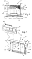
- Fig. 4 shows an exploded view of the individual elements of the cable connector shell 10.
- the housing 12 in order to reduce the overall height of the cable connector shell 10, the housing 12 should be just big enough to encompass the printed circuit board 28 and electronic circuitry 26 together with the connectors and connector elements 42 to 46. It is useful in such situations to use four row (or more) connector elements, i.e., wherein the individual male and female contact elements are arranged in four rows. This helps reduces the length of the connector elements and, in particular, the length of the first connector 42 and its respective second connector element 44. That way the second connector element will not occupy the complete length of the upper edge of the printed circuit board 28 (see Fig. 2 and 4).
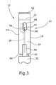
- the printed circuit board 28 with a cutout section 56 located adjacent and close to the opening 36. From Fig. 3, one can see that the level of the upper edge 54 of the printed circuit board 28 is below or within the lower area of the opening 36 of the housing 12. That means that within the housing 12, and close to the opening 36, there is additional available space for the wires 34 although the cables 32 are located rather close to the printed circuit board 28.
- the upper side wall 22 and the vertical side wall 24 with the opening 36 are each provided with handle elements 58,60 configured as flange portions 62,64.
- the handle elements 58,60 laterally project from their respective side walls 12.
- Other handle elements known in the prior art of cable connector shells are also acceptable.
- the connector elements of the cable connector shell 10 and the electronic equipment 52 can include a significant number of contact elements (up to 128 and more). Accordingly, the connector elements should be aligned with each other when engaging and disengaging them.
- Guidance is provided in the instant embodiment by means of cooperating guiding elements 66 and 68 attached to the cable connector shell 10 and the electronic equipment 52.
- the respective guiding elements 66,68 cooperate with each other.
- each pair of guiding elements 66,68 comprises one guiding element 68 built as a pin and projecting from the electronic device 52 while the other guiding element 66 comprises a body having a bore 70 therein for glidingly receiving the guiding element 68.
- the housing 12 of the shell 10 When engaging the cable connector shell 10 with the electronic equipment 52, the housing 12 of the shell 10 is guided towards the electronic equipment 52 in that the guiding elements 68 are received by the guiding elements 66. Prior to the engagement of the connector elements of the cable connector shell 10 and the electronic equipment 52 the guiding elements 68 are already received by the bores 70 of the guiding element 66 to such an extent that any tilting or lateral relative movements of the shell 10 and the electronic equipment 52 can be substantially prevented.
- the housing 12 can be mechanically fixed to the electronic equipment 52 by any known suitable engageable and disengageable fastening means like thumb screws or other kinds of screws, bail mount, or the like.
- Figs. 6 and 7 show another embodiment of a multiple wire cable connector shell 10' which except for two features is more or less identical to the shell 10 of Figs. 1 to 5. Both alternative features can be used separately from or in combination with each other.
- the first alternative feature relates to the provision of the first connector 42' as a card-edge connector element 40' connected to the wires 34' and interacting with a mating connector element 44' comprising individual contact pads 45' on one or both sides of the printed circuit board 28' along its edge 54' (see Fig. 7). With the printed circuit board 28' by sliding the card-edge connector element 40' onto the edge 54' of the printed circuit board 28' contact elements 47' of the card-edge connector element 40' are in contact with the contact pads 45' of the printed circuit board 28'.
- the other alternative feature of the embodiment of Figs. 6 and 7 relates to provision of an additional connector element 49' arranged between the third connector 46' and the printed circuit board 28'.
- the additional connector element 49' is an edge-mountable connector element electrically connected to the printed circuit board 28'.
- the third connector element 46' is fixed to the housing 12'.
- the third and additional connector elements 46',49' are engageable and disengageable. Accordingly, when removing the electronic circuitry 26' from the housing 12', the additional connector element 49' is disengaged from the third connector element 46' which remains in the housing 12.
- the third connector element 46 of the embodiment of the multiple wire cable connector shell 10 according to Figs. 1 to 5 or the additional connector element 49' of the embodiment according to Figs. 6 and 7 can be provided as a card-edge connector element similar to the card-edge connector element 40' of the multiple wire cable connector shell 10' of Figs. 6 and 7.
Landscapes
- Details Of Connecting Devices For Male And Female Coupling (AREA)
Priority Applications (3)
| Application Number | Priority Date | Filing Date | Title |
|---|---|---|---|
| EP02028340A EP1432078A1 (fr) | 2002-12-17 | 2002-12-17 | Enveloppe pour connecteur de cable |
| AU2003303533A AU2003303533A1 (en) | 2002-12-17 | 2003-11-04 | Cable connector shell |
| PCT/US2003/035285 WO2004062334A1 (fr) | 2002-12-17 | 2003-11-04 | Gaine de connecteur de cable |
Applications Claiming Priority (1)
| Application Number | Priority Date | Filing Date | Title |
|---|---|---|---|
| EP02028340A EP1432078A1 (fr) | 2002-12-17 | 2002-12-17 | Enveloppe pour connecteur de cable |
Publications (1)
| Publication Number | Publication Date |
|---|---|
| EP1432078A1 true EP1432078A1 (fr) | 2004-06-23 |
Family
ID=32338031
Family Applications (1)
| Application Number | Title | Priority Date | Filing Date |
|---|---|---|---|
| EP02028340A Withdrawn EP1432078A1 (fr) | 2002-12-17 | 2002-12-17 | Enveloppe pour connecteur de cable |
Country Status (3)
| Country | Link |
|---|---|
| EP (1) | EP1432078A1 (fr) |
| AU (1) | AU2003303533A1 (fr) |
| WO (1) | WO2004062334A1 (fr) |
Cited By (2)
| Publication number | Priority date | Publication date | Assignee | Title |
|---|---|---|---|---|
| FR2879834A1 (fr) * | 2004-12-20 | 2006-06-23 | Thales Sa | Boitier d'appareillage electronique |
| NL1033681C2 (nl) * | 2006-04-14 | 2007-12-20 | Sumitomo Electric Industries | Aan een connector verbonden kabelsamenstel. |
Citations (14)
| Publication number | Priority date | Publication date | Assignee | Title |
|---|---|---|---|---|
| US4242721A (en) * | 1977-10-20 | 1980-12-30 | Bunker Ramo Corporation | Electrical connector assembly for interconnecting remote signal stations to central signal processing systems |
| US4386819A (en) * | 1981-08-31 | 1983-06-07 | Amp Incorporated | RF Shielded assembly having capacitive coupling feature |
| GB2123614A (en) * | 1982-06-23 | 1984-02-01 | Elektrowatt Ag | Module mounting apparatus |
| EP0259897A1 (fr) * | 1982-04-15 | 1988-03-16 | Sumitomo Wiring Systems, Ltd. | Système de jonction électrique |
| EP0263391A2 (fr) * | 1986-10-04 | 1988-04-13 | Endress u. Hauser GmbH u. Co. | Dispositif pour recevoir, préparer, exploiter et transmettre des signaux électriques |
| US5308264A (en) * | 1993-04-15 | 1994-05-03 | United Technologies Corporation | Modular backshell interface system |
| DE9405917U1 (de) * | 1994-04-09 | 1995-08-10 | Murrelektronik AG, Beringen | Bus-System |
| EP0782216A2 (fr) * | 1995-12-14 | 1997-07-02 | Sumitomo Wiring Systems, Ltd. | Boîtier de connexion électrique, construction de la connexion, construction pour la fixation d'une barre de distribution et borne de raccordement |
| EP0793249A2 (fr) * | 1996-02-28 | 1997-09-03 | Harness System Technologies Research, Ltd. | Boîtier de connexion électrique |
| US5827074A (en) * | 1993-11-01 | 1998-10-27 | Motorola, Inc. | End mounting terminator for backplanes |
| EP0952637A1 (fr) * | 1998-04-24 | 1999-10-27 | Nothern Telecom Limited | Connecteur pour câbles coaxiaux |
| US6243273B1 (en) * | 1999-09-01 | 2001-06-05 | Nortel Networks Limited | Mini-backplane “T” assembly |
| EP1122821A2 (fr) * | 2000-02-01 | 2001-08-08 | 3M Innovative Properties Company | Magasin de protection contre la surtension de télécommunications et un point de distribution |
| WO2002011249A1 (fr) * | 2000-07-27 | 2002-02-07 | Tyco Electronics Corporation | Borniers et procedes permettant d'etablir et d'interrompre des connections dans un conducteur de telecommunications |
-
2002
- 2002-12-17 EP EP02028340A patent/EP1432078A1/fr not_active Withdrawn
-
2003
- 2003-11-04 WO PCT/US2003/035285 patent/WO2004062334A1/fr not_active Ceased
- 2003-11-04 AU AU2003303533A patent/AU2003303533A1/en not_active Abandoned
Patent Citations (14)
| Publication number | Priority date | Publication date | Assignee | Title |
|---|---|---|---|---|
| US4242721A (en) * | 1977-10-20 | 1980-12-30 | Bunker Ramo Corporation | Electrical connector assembly for interconnecting remote signal stations to central signal processing systems |
| US4386819A (en) * | 1981-08-31 | 1983-06-07 | Amp Incorporated | RF Shielded assembly having capacitive coupling feature |
| EP0259897A1 (fr) * | 1982-04-15 | 1988-03-16 | Sumitomo Wiring Systems, Ltd. | Système de jonction électrique |
| GB2123614A (en) * | 1982-06-23 | 1984-02-01 | Elektrowatt Ag | Module mounting apparatus |
| EP0263391A2 (fr) * | 1986-10-04 | 1988-04-13 | Endress u. Hauser GmbH u. Co. | Dispositif pour recevoir, préparer, exploiter et transmettre des signaux électriques |
| US5308264A (en) * | 1993-04-15 | 1994-05-03 | United Technologies Corporation | Modular backshell interface system |
| US5827074A (en) * | 1993-11-01 | 1998-10-27 | Motorola, Inc. | End mounting terminator for backplanes |
| DE9405917U1 (de) * | 1994-04-09 | 1995-08-10 | Murrelektronik AG, Beringen | Bus-System |
| EP0782216A2 (fr) * | 1995-12-14 | 1997-07-02 | Sumitomo Wiring Systems, Ltd. | Boîtier de connexion électrique, construction de la connexion, construction pour la fixation d'une barre de distribution et borne de raccordement |
| EP0793249A2 (fr) * | 1996-02-28 | 1997-09-03 | Harness System Technologies Research, Ltd. | Boîtier de connexion électrique |
| EP0952637A1 (fr) * | 1998-04-24 | 1999-10-27 | Nothern Telecom Limited | Connecteur pour câbles coaxiaux |
| US6243273B1 (en) * | 1999-09-01 | 2001-06-05 | Nortel Networks Limited | Mini-backplane “T” assembly |
| EP1122821A2 (fr) * | 2000-02-01 | 2001-08-08 | 3M Innovative Properties Company | Magasin de protection contre la surtension de télécommunications et un point de distribution |
| WO2002011249A1 (fr) * | 2000-07-27 | 2002-02-07 | Tyco Electronics Corporation | Borniers et procedes permettant d'etablir et d'interrompre des connections dans un conducteur de telecommunications |
Cited By (4)
| Publication number | Priority date | Publication date | Assignee | Title |
|---|---|---|---|---|
| FR2879834A1 (fr) * | 2004-12-20 | 2006-06-23 | Thales Sa | Boitier d'appareillage electronique |
| WO2006067001A1 (fr) * | 2004-12-20 | 2006-06-29 | Thales | Boitier d'appareillage electronique |
| NL1033681C2 (nl) * | 2006-04-14 | 2007-12-20 | Sumitomo Electric Industries | Aan een connector verbonden kabelsamenstel. |
| CN101055965B (zh) * | 2006-04-14 | 2010-08-25 | 住友电气工业株式会社 | 带连接器的多芯电缆 |
Also Published As
| Publication number | Publication date |
|---|---|
| WO2004062334A1 (fr) | 2004-07-22 |
| WO2004062334A8 (fr) | 2005-02-24 |
| AU2003303533A1 (en) | 2004-07-29 |
Similar Documents
| Publication | Publication Date | Title |
|---|---|---|
| EP0405454B1 (fr) | Elément coaxial de contact | |
| US4632476A (en) | Terminal grounding unit | |
| US6347963B1 (en) | Interchangeable backplane interface connection panel | |
| US7909643B2 (en) | Cassette for a cable interconnect system | |
| EP0657834A1 (fr) | Modem au format de carte de crédit avec module pour accés de données | |
| US20040067680A1 (en) | Cable connector assembly | |
| EP0175426B1 (fr) | Connecteur adaptatif pour la transition entre deux systèmes de mesure utilisant une plaquette à circuit imprimé | |
| CN112086827B (zh) | 用于传输超高频信号的紧凑型同轴线缆连接器 | |
| US20080311794A1 (en) | Modular jack with removable contact array | |
| US8597036B2 (en) | Transceiver assembly | |
| US11677174B2 (en) | Decoupled spring and electrical path in connector interface | |
| US20250329958A1 (en) | High density coupling panel | |
| WO2004039091A2 (fr) | Systeme de correction haute densite | |
| EP0614248B1 (fr) | Interface pour un réseau local (LAN) | |
| EP1089397B1 (fr) | Connecteur électrique ayant des moyens de retenue pour la fixation détachable d'un boîtier de composants | |
| CN111082242B (zh) | 一种连接器、电路板及通信设备 | |
| US6146153A (en) | Adapter apparatus and method for transmitting electronic data | |
| US6324610B1 (en) | Shared multi-port communications device and associated methods | |
| US6280257B1 (en) | Cable dock fixture with EMI shielding | |
| US8496486B2 (en) | Transceiver assembly | |
| WO2019219847A1 (fr) | Connecteur à haute densité | |
| US7175475B2 (en) | Receptacle for copper wire transceivers | |
| WO2003077264A9 (fr) | Module a blindage antiparasite | |
| EP2224546B1 (fr) | Cassette dotée de connecteurs d'accouplement à l'arrière interchangeables | |
| EP0691070B1 (fr) | Dispositif permettant de connecter une plaquette de circuits imprimes sur une plaque de raccordement |
Legal Events
| Date | Code | Title | Description |
|---|---|---|---|
| PUAI | Public reference made under article 153(3) epc to a published international application that has entered the european phase |
Free format text: ORIGINAL CODE: 0009012 |
|
| AK | Designated contracting states |
Kind code of ref document: A1 Designated state(s): AT BE BG CH CY CZ DE DK EE ES FI FR GB GR IE IT LI LU MC NL PT SE SI SK TR |
|
| AX | Request for extension of the european patent |
Extension state: AL LT LV MK RO |
|
| STAA | Information on the status of an ep patent application or granted ep patent |
Free format text: STATUS: THE APPLICATION HAS BEEN WITHDRAWN |
|
| 16A | New documents despatched to applicant after publication of the search report |
Effective date: 20041123 |
|
| RIC1 | Information provided on ipc code assigned before grant |
Ipc: 7H 01R 9/24 B Ipc: 7H 05K 7/14 A |
|
| 18W | Application withdrawn |
Effective date: 20041209 |