EP1432079A1 - Dispositif de contact et dispositif de connexion pour un support de contact - Google Patents
Dispositif de contact et dispositif de connexion pour un support de contact Download PDFInfo
- Publication number
- EP1432079A1 EP1432079A1 EP03027670A EP03027670A EP1432079A1 EP 1432079 A1 EP1432079 A1 EP 1432079A1 EP 03027670 A EP03027670 A EP 03027670A EP 03027670 A EP03027670 A EP 03027670A EP 1432079 A1 EP1432079 A1 EP 1432079A1
- Authority
- EP
- European Patent Office
- Prior art keywords
- contact
- housing
- locking element
- contacting
- carrier
- Prior art date
- Legal status (The legal status is an assumption and is not a legal conclusion. Google has not performed a legal analysis and makes no representation as to the accuracy of the status listed.)
- Withdrawn
Links
- 239000000969 carrier Substances 0.000 claims abstract description 7
- 239000004020 conductor Substances 0.000 description 26
- 230000037431 insertion Effects 0.000 description 4
- 238000003780 insertion Methods 0.000 description 4
- 230000013228 contact guidance Effects 0.000 description 1
- 230000001419 dependent effect Effects 0.000 description 1
- 238000004519 manufacturing process Methods 0.000 description 1
- 239000000463 material Substances 0.000 description 1
- 238000007789 sealing Methods 0.000 description 1
- 239000007787 solid Substances 0.000 description 1
- XLYOFNOQVPJJNP-UHFFFAOYSA-N water Substances O XLYOFNOQVPJJNP-UHFFFAOYSA-N 0.000 description 1
Images

Classifications
-
- H—ELECTRICITY
- H01—ELECTRIC ELEMENTS
- H01R—ELECTRICALLY-CONDUCTIVE CONNECTIONS; STRUCTURAL ASSOCIATIONS OF A PLURALITY OF MUTUALLY-INSULATED ELECTRICAL CONNECTING ELEMENTS; COUPLING DEVICES; CURRENT COLLECTORS
- H01R12/00—Structural associations of a plurality of mutually-insulated electrical connecting elements, specially adapted for printed circuits, e.g. printed circuit boards [PCB], flat or ribbon cables, or like generally planar structures, e.g. terminal strips, terminal blocks; Coupling devices specially adapted for printed circuits, flat or ribbon cables, or like generally planar structures; Terminals specially adapted for contact with, or insertion into, printed circuits, flat or ribbon cables, or like generally planar structures
- H01R12/70—Coupling devices
- H01R12/82—Coupling devices connected with low or zero insertion force
- H01R12/85—Coupling devices connected with low or zero insertion force contact pressure producing means, contacts activated after insertion of printed circuits or like structures
- H01R12/89—Coupling devices connected with low or zero insertion force contact pressure producing means, contacts activated after insertion of printed circuits or like structures acting manually by moving connector housing parts linearly, e.g. slider
-
- H—ELECTRICITY
- H01—ELECTRIC ELEMENTS
- H01R—ELECTRICALLY-CONDUCTIVE CONNECTIONS; STRUCTURAL ASSOCIATIONS OF A PLURALITY OF MUTUALLY-INSULATED ELECTRICAL CONNECTING ELEMENTS; COUPLING DEVICES; CURRENT COLLECTORS
- H01R12/00—Structural associations of a plurality of mutually-insulated electrical connecting elements, specially adapted for printed circuits, e.g. printed circuit boards [PCB], flat or ribbon cables, or like generally planar structures, e.g. terminal strips, terminal blocks; Coupling devices specially adapted for printed circuits, flat or ribbon cables, or like generally planar structures; Terminals specially adapted for contact with, or insertion into, printed circuits, flat or ribbon cables, or like generally planar structures
- H01R12/70—Coupling devices
- H01R12/77—Coupling devices for flexible printed circuits, flat or ribbon cables or like structures
- H01R12/78—Coupling devices for flexible printed circuits, flat or ribbon cables or like structures connecting to other flexible printed circuits, flat or ribbon cables or like structures
-
- H—ELECTRICITY
- H01—ELECTRIC ELEMENTS
- H01R—ELECTRICALLY-CONDUCTIVE CONNECTIONS; STRUCTURAL ASSOCIATIONS OF A PLURALITY OF MUTUALLY-INSULATED ELECTRICAL CONNECTING ELEMENTS; COUPLING DEVICES; CURRENT COLLECTORS
- H01R13/00—Details of coupling devices of the kinds covered by groups H01R12/70 or H01R24/00 - H01R33/00
- H01R13/62—Means for facilitating engagement or disengagement of coupling parts or for holding them in engagement
- H01R13/629—Additional means for facilitating engagement or disengagement of coupling parts, e.g. aligning or guiding means, levers, gas pressure electrical locking indicators, manufacturing tolerances
- H01R13/62905—Additional means for facilitating engagement or disengagement of coupling parts, e.g. aligning or guiding means, levers, gas pressure electrical locking indicators, manufacturing tolerances comprising a camming member
Definitions
- the invention relates to a contacting device for Contacting a contact carrier provided with a contact surface, especially a ribbon cable.
- the invention further relates to a connection device for at least two contact carriers.
- Contacting devices for ribbon cables usually have a contact bar with contact elements is formed.
- a contact bar with contact elements is formed.
- Such a contact guidance device is, for example shown in the publication US 5,904,589.
- the contact elements are usually only in one Bent direction, so that in the contacted state, the contact surface of the ribbon cable with a constant force one of the surfaces of the ribbon conductor is applied, where the ribbon cable with continuous exposure to this Force can bend.
- the Force to insert the ribbon cable should not be so great that the ribbon cable bends. This is the contacting force the contact elements on the ribbon cable limited so that the ribbon cable in the contacting device is held only by a limited force and with a low tensile load from the contacting device can slip out.
- a contacting device is known from the publication US Pat. No. 5,240,430 known that a contact element for contacting a ribbon cable.
- the contact element has one Contact arm on which by moving a locking element, on another arm of the contact element supports, - is pressed against the ribbon cable.
- the ribbon cable can also be used for the subject of this document in the contacted state by the one-way Force may be bent, causing damage to the ribbon cable can be.
- the subject of this Publication of the ribbon cable between two contact arms held, thereby reducing the clamping force from the elasticity of the Contact element material depends and therefore not arbitrarily high can be.
- the object of the present invention is a contacting device to create for a contact carrier in which the contact carrier is held by an increased clamping force and where possible the contact carrier not by the clamping force is bent. It is still the task of the present Invention to provide a connecting device with the two contact carriers can be connected to each other.
- This task is performed by the contacting device Claim 1 and by the connecting device according to claim 10 solved.
- one is Contacting device for contacting a Contact surface provided contact carrier provided.
- the contacting device has a housing in which a first and a second contact element are arranged with The distance from each other is arranged to be between the Include contact carrier with the contact surface. It is still a locking element for jamming the contact carrier provided in the housing. This is the locking element with the first and the second contact element coupled to when the locking element moves with respect to the housing, the first and the second contact element move against each other so that the between the first and the second contact element can be arranged contact carrier is jammed.
- the contact area is marked by contacted the first or the second contact element, each after which of the contact elements faces the contact surface is.
- a contacting device which allows the contact carrier to be between to jam the contact elements that the contact carrier essentially not subjected to a one-sided force is so that the contact carrier is not bent becomes.
- the clamping force be increased so that the contact carrier better in the Contacting device is held.
- first and the second Contact element are designed to be resilient to Jamming the contact carrier a permanent force on the To exercise contact carriers.
- first and the second contact element each have a sliding section, the Sliding sections of the first and the second contact element upon movement of the locking element in each case on one Slide the sliding surface of the locking element along, the sliding surfaces are designed so that when moving the locking element a counter movement of the first and the second contact element is effected.
- the locking element both the first and the second at the same time Contact element moved against the contact carrier and jammed, when the locking element is in a predetermined Way is moved.
- the movement is preferably a translatory movement and the sliding surfaces are as inclined planes with respect to the Contact elements formed. This can be done by moving the locking element, for example along a guide the sliding sections of the contact elements on the sliding surfaces slide along and at the same time essentially one movement directed vertically to the translatory movement of the contact elements.
- the sliding surfaces of the locking element are preferably designed to go through the housing with the help of support surfaces are supported so that a jamming force caused by the contact elements acts on the sliding surfaces, essentially is accommodated by the housing. That way a particularly high force is exerted on the contact carrier, which is essentially due to the resilience of the elements Housing, support surface and sliding surface determined.
- the locking element with the housing in a first position in which the contact carrier is not jammed can be locked, so that the locking element is held on the housing. To this Way can be ensured with a locking element that there is no contact carrier through the contacting device contacted, cannot be lost.
- the locking element is in a second with the housing Lockable position in which the contact carrier is jammed. This prevents the locking element accidentally moved so from the second position that the jamming of the contact carrier is released.
- the sliding surfaces as inclined plane is due to the lockability in the second position ensures that by the counterforce the contact elements on the inclined plane the force no loosening in the direction of movement of the locking element the locking is effected.
- the locking element is preferably in the direction of insertable contact carrier on the housing movable to the Clamp contact carrier.
- the locking element has For this purpose, an opening for the contact carrier through which the Contact carrier introduced into the contacting device can be.
- a connecting device for at least two contact carriers provided the two contacting devices described above Has shape.
- the housing of the contacting devices are made in one piece. That way a connecting device for two contact carriers is provided be that is particularly easy to implement, the Locking elements are constructed identically, so that the Assembly of such a connecting device is considerably simplified is.
- the first and the second contact elements are preferably made in one piece, so that an electrical connection each between the first contact elements and between each the second contact elements. This will also the number of components for such a connection device significantly reduced and thus the manufacturing simplified.
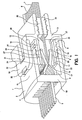
- Fig. 1 is a contacting device 1 according to a first embodiment of the invention shown.
- the representation shows a section of the contacting device 1.
- the contacting device 1 has a housing 2, in which first contact elements 3 and second contact elements 4 are arranged. At least one of the first contact elements 3 or one of the second contact elements 4 are each in electrical connection with a contact pin 5, which consists of a Surface of the housing 2, preferably from that of the insertion opening of the housing opposite surface protrudes.
- a ribbon conductor 6 can be inserted, the conductor tracks at least on the side facing the second contact elements 4 wearing. It can be used with such a contacting device a circuit board can also be contacted.
- the conductor tracks 7 are essentially parallel to one another arranged, the arrangement of the second contact elements 4 is designed so that it can be placed on the conductor tracks 7 and can contact them in this way.
- a locking element 8 is attached to the housing 2, that in the direction of the insertion of the ribbon cable 6 the housing 2 is slidable.
- the locking element 8 has a first guide surface 9 and a second guide surface 10 on the sides of the housing 2 and a guide of the locking element enable on the housing 2.
- the locking element 8 has a first guide element 11 and a second guide element 12.
- the first and second guide elements 11, 12 are essentially between the guide surfaces 9, 10 and essentially arranged parallel to them.
- the guide areas are kept 9, 10 and the guide elements 11, 12 by a carrier element 13, which is part of the locking element 8.
- The are first guide surface 9 and first guide element 11 spaced on the support member 13 so that a first wall 14 of the housing 2 is slidably disposed therebetween is.
- the distance between the second guide surface 10 and the second guide element 12 is also so large that a second wall 15 of the housing 2 is slidable therein can be arranged.
- seals 16 are arranged, which protect against the ingress of moisture between the housing 2 and the locking element 8 can offer.
- the first guide element 11 has a first sliding surface 20 on, which faces the first contact element 3.
- the first Contact element 3 is essentially resilient and has a contact surface 17 and a sliding portion 18 on the first sliding surface 20 of the first Guide element 11 rests.
- the first contacting element 3 is held on a holding wall 19 of the housing 2.
- the first contacting element 3 is essentially designed that by moving the sliding section 18 vertically contacting the inserted flat conductor 6 Contact surface 17 with the conductor tracks 7 of the ribbon conductor 6 or a mere placement of the contact surface on the ribbon cable 6, if none at the attachment point Conductor 7 is arranged, is effected.
- the first sliding surface 20 of the first guide element 11 has a beveled step 21 through a first sliding surface section 22 and a second sliding surface section 23 of the first sliding surface 20 separated from one another are.
- the first sliding surface section and the second Sliding surface sections 22, 23 lie with respect to the ribbon conductor 6 at different levels, being by moving of the locking element 8 in the direction of the housing first contact element 3 with its sliding section 18 on the first sliding surface section 22 slides, then through the beveled step 21 in the direction of the ribbon conductor 6 is raised and then up to the second sliding surface section 23 slides.
- the second contact element 4 and the second guide element 12 are essentially symmetrical, wherein the second contacting element 4 has a second contacting surface 24 and a second sliding section 25.
- the second contact element 4 is like that first contacting element 3 on the holding wall 19 of the housing 2 attached.
- the second guide element 12 has one second sliding surface 26 on which the second sliding portion of the second contact element 4 slides.
- the second sliding surface 26 has a third sliding surface section 27 and one fourth sliding surface section 28, which pass through each other a second beveled step 29 are separated.
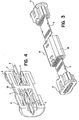
- Fig. 2 the contacting device in one Ribbon conductor 6 shown contacting position.
- the Ribbon conductor 6 is located between the first and the second contact element 3, 4 with their contact surfaces 17, 24 on the respective conductor tracks 7, if on the each side of the ribbon cable available, pressed are.
- the contacting force of the contacting surfaces 17, 24 results from the deflection of the sliding sections 18, 25 in the direction of the ribbon cable 6 and the respective spring force the contact elements 3, 4.
- the flat ribbon conductor can preferably be provided with a sealing pad 30 be provided, which has an opening in the holding wall 13 which the ribbon cable 6 is guided against moisture and seal water.
- the between the guide elements 11, 12 and the walls of the Housing arranged seals 16 are capable of To absorb force from the ribbon cable 6 and the respective Contact element 3, 4 to the respective guide element 11, 12 is passed on. The force is then attached to the particular one Wall 14, 15 of the housing 2 forwarded, and added there. In this way, the guide elements can bend 11, 12 by the contacting force of the contact elements 3, 4 on the ribbon cable can be avoided. are no seals are provided, the respective guide element 11, 12 designed so that with the respective wall 14, 15 of the housing communicates so that the force is applied directly the housing 2 is passed on.
- first locking elements 31 are provided, on the one hand, the locking element 8 in a non-locking first position to hold so that it does not slide away from the housing 20 can.
- the first locking elements 31 act with a locking surface 32 of the respective guide surface 9, 10 together.
- the guide surfaces 9, 10 are preferably U-shaped, the inner surfaces of the U-shaped shape being used as guides serve. The guidance is limited by the side the locking elements 31 and the inside of the U-shape.
- second latching elements 33 that it allow the locking element 8 in a locked Hold position so that no unintended shift of the locking element 8 take place away from the housing can.
- the housing 2 is essentially the locking element 8, the first and second contact elements 3, 4 symmetrical built up so that when mounting not on the respective Alignment of the individual parts is important. This will assembly considerably simplified.
- the first and second contact elements 3, 4 can each be formed in one piece as well as separately from each other after whether the ribbon conductor 6 contacts only on one side must be or whether the ribbon cable 6 on both sides has interconnects 7 which are electrically separated from one another.
- Fig. 3 is a connecting device for connecting two ribbon conductors 6 shown, the two according to the invention Has contacting devices 1.
- the connection device 34 has a housing 35, which consists essentially of two with contacting devices attached to one another on their retaining walls 19 1 is formed.
- the housing 35 made in one piece, so that the insertion openings for the ribbon conductor 6 to be connected are essentially opposite.
- Locking elements 8 can be placed, essentially on same way as previously described with the housing and the interacting contact elements located therein.
- the respective contact elements are located essentially also for the two connection sides opposite and are electrically connected. It can preferably be provided that the respective first Contact elements 3 and the respective second contact elements 4 of the two connection sides are electrically connected to one another are preferably made in one piece, each of the first contact elements of one connection side with each opposite corresponding first contact element the opposite connection side is connected.
- the contacting device enables one Fixation of a ribbon cable or a printed circuit board, in which a high with the help of a locking element Clamping force exerted on the ribbon conductor or the printed circuit board becomes. Because of the clamping force between two contact elements is exercised, the ribbon cable can do not bend and are not damaged as a result. When contacting a solid circuit board, can therefore damage can be avoided by breaking the circuit board.
- connection device When using the contacting device according to the invention for a connection device ensures the high Holding force of the contacting device 1 a reliable and connection of two ribbon cables that can withstand tensile forces, two circuit boards, or between a circuit board and a ribbon cable.
Landscapes
- Coupling Device And Connection With Printed Circuit (AREA)
Priority Applications (1)
| Application Number | Priority Date | Filing Date | Title |
|---|---|---|---|
| EP03027670A EP1432079A1 (fr) | 2002-12-17 | 2003-12-03 | Dispositif de contact et dispositif de connexion pour un support de contact |
Applications Claiming Priority (3)
| Application Number | Priority Date | Filing Date | Title |
|---|---|---|---|
| EP02028347 | 2002-12-17 | ||
| EP02028347 | 2002-12-17 | ||
| EP03027670A EP1432079A1 (fr) | 2002-12-17 | 2003-12-03 | Dispositif de contact et dispositif de connexion pour un support de contact |
Publications (1)
| Publication Number | Publication Date |
|---|---|
| EP1432079A1 true EP1432079A1 (fr) | 2004-06-23 |
Family
ID=32395438
Family Applications (1)
| Application Number | Title | Priority Date | Filing Date |
|---|---|---|---|
| EP03027670A Withdrawn EP1432079A1 (fr) | 2002-12-17 | 2003-12-03 | Dispositif de contact et dispositif de connexion pour un support de contact |
Country Status (1)
| Country | Link |
|---|---|
| EP (1) | EP1432079A1 (fr) |
Cited By (7)
| Publication number | Priority date | Publication date | Assignee | Title |
|---|---|---|---|---|
| WO2008066714A3 (fr) * | 2006-11-15 | 2008-08-21 | Molex Inc | Connecteur de bord avec bouchons de pré-chargement |
| WO2008143997A1 (fr) * | 2007-05-17 | 2008-11-27 | Molex Incorporated | Connecteur de câble |
| ITMI20091986A1 (it) * | 2009-11-12 | 2011-05-13 | Selecom S R L | Connettore per circuiti stampati flessibili a collegamento facilitato |
| WO2012123222A1 (fr) * | 2011-03-15 | 2012-09-20 | Robert Bosch Gmbh | Connecteur de contact pour mise en contact directe d'une carte de circuits imprimés |
| WO2012142606A2 (fr) | 2011-04-15 | 2012-10-18 | Hypertronics Corporation | Connecteur électrique à haute densité comportant une carte de circuit imprimé |
| CN103620885B (zh) * | 2011-04-15 | 2016-11-30 | 希佩尔特罗尼克斯公司 | 具有印刷电路板的高密度电连接器 |
| CN112217064A (zh) * | 2019-07-11 | 2021-01-12 | 泰连德国有限公司 | 为车辆中的布线提供接触的触头载体 |
Citations (8)
| Publication number | Priority date | Publication date | Assignee | Title |
|---|---|---|---|---|
| US3474387A (en) * | 1967-04-13 | 1969-10-21 | Elco Corp | Zero insertion force connector and contact therefor |
| US4220382A (en) * | 1978-12-15 | 1980-09-02 | Amp Incorporated | Bussing connector |
| US4400049A (en) * | 1981-08-12 | 1983-08-23 | Ncr Corporation | Connector for interconnecting circuit boards |
| US4480886A (en) * | 1982-03-02 | 1984-11-06 | Zetronic S.P.A. | Quick connector for a multi-conductor circuit |
| US4919626A (en) * | 1989-04-14 | 1990-04-24 | Itt Corporation | Connector for IC card |
| US5145381A (en) * | 1991-08-22 | 1992-09-08 | Amp Incorporated | Wedge driven elastomeric connector |
| EP0505744A2 (fr) * | 1991-03-28 | 1992-09-30 | Richard Hirschmann GmbH & Co. | Connecteur pour une plaquette à circuits imprimés |
| US5839916A (en) * | 1994-05-31 | 1998-11-24 | Sumitomo Wiring Systems, Ltd. | Device for connecting a flat cable to a wiring board |
-
2003
- 2003-12-03 EP EP03027670A patent/EP1432079A1/fr not_active Withdrawn
Patent Citations (8)
| Publication number | Priority date | Publication date | Assignee | Title |
|---|---|---|---|---|
| US3474387A (en) * | 1967-04-13 | 1969-10-21 | Elco Corp | Zero insertion force connector and contact therefor |
| US4220382A (en) * | 1978-12-15 | 1980-09-02 | Amp Incorporated | Bussing connector |
| US4400049A (en) * | 1981-08-12 | 1983-08-23 | Ncr Corporation | Connector for interconnecting circuit boards |
| US4480886A (en) * | 1982-03-02 | 1984-11-06 | Zetronic S.P.A. | Quick connector for a multi-conductor circuit |
| US4919626A (en) * | 1989-04-14 | 1990-04-24 | Itt Corporation | Connector for IC card |
| EP0505744A2 (fr) * | 1991-03-28 | 1992-09-30 | Richard Hirschmann GmbH & Co. | Connecteur pour une plaquette à circuits imprimés |
| US5145381A (en) * | 1991-08-22 | 1992-09-08 | Amp Incorporated | Wedge driven elastomeric connector |
| US5839916A (en) * | 1994-05-31 | 1998-11-24 | Sumitomo Wiring Systems, Ltd. | Device for connecting a flat cable to a wiring board |
Cited By (11)
| Publication number | Priority date | Publication date | Assignee | Title |
|---|---|---|---|---|
| WO2008066714A3 (fr) * | 2006-11-15 | 2008-08-21 | Molex Inc | Connecteur de bord avec bouchons de pré-chargement |
| US7946889B2 (en) | 2006-11-15 | 2011-05-24 | Molex Incorporated | Edge connector with preload caps |
| CN101584086B (zh) * | 2006-11-15 | 2012-01-11 | 莫列斯公司 | 具有预载荷盖的边缘连接器 |
| WO2008143997A1 (fr) * | 2007-05-17 | 2008-11-27 | Molex Incorporated | Connecteur de câble |
| ITMI20091986A1 (it) * | 2009-11-12 | 2011-05-13 | Selecom S R L | Connettore per circuiti stampati flessibili a collegamento facilitato |
| WO2012123222A1 (fr) * | 2011-03-15 | 2012-09-20 | Robert Bosch Gmbh | Connecteur de contact pour mise en contact directe d'une carte de circuits imprimés |
| WO2012142606A2 (fr) | 2011-04-15 | 2012-10-18 | Hypertronics Corporation | Connecteur électrique à haute densité comportant une carte de circuit imprimé |
| CN103620885A (zh) * | 2011-04-15 | 2014-03-05 | 希佩尔特罗尼克斯公司 | 具有印刷电路板的高密度电连接器 |
| EP2697871A4 (fr) * | 2011-04-15 | 2014-09-17 | Hypertronics Corp | Connecteur électrique à haute densité comportant une carte de circuit imprimé |
| CN103620885B (zh) * | 2011-04-15 | 2016-11-30 | 希佩尔特罗尼克斯公司 | 具有印刷电路板的高密度电连接器 |
| CN112217064A (zh) * | 2019-07-11 | 2021-01-12 | 泰连德国有限公司 | 为车辆中的布线提供接触的触头载体 |
Similar Documents
| Publication | Publication Date | Title |
|---|---|---|
| DE102015101893B4 (de) | Leiteranschlussklemme | |
| EP0730785B1 (fr) | Borne de connexion pour installations electriques | |
| DE69508396T2 (de) | Schieneneinheit | |
| EP1096606B1 (fr) | Borne de connexion | |
| DE10355195B4 (de) | Leiteranschluss | |
| DE10340571B3 (de) | Klemme zum Halten von flachen Gegenständen | |
| EP1207588A1 (fr) | Connecteur électrique pour cable plat ou circuit imprimé flexible | |
| DE2638418A1 (de) | Niedrigprofil-ic-fassung | |
| EP1559171A2 (fr) | Connecteur destine au raccordement de deux conducteurs plats et systeme connecteur associe | |
| DE19857624B4 (de) | Verbinderanordnung für flache Schaltungseinrichtungen | |
| DE10103107A1 (de) | Anschlußklemme für elektrische Leiter | |
| EP1484822A1 (fr) | Connecteur | |
| DE102016108825A1 (de) | Klemmanordnung und Anschlussklemme | |
| DE102007017059B4 (de) | Sockel für elektrische Bauteile | |
| DE102021104504A1 (de) | Anschlussanordnung, Anschlussklemme und elektronisches Gerät | |
| EP1432079A1 (fr) | Dispositif de contact et dispositif de connexion pour un support de contact | |
| DE202004000419U1 (de) | Schraubenlose Leiteranschlussklemme | |
| EP0465883B1 (fr) | Borne de connexion pour fixation sur un rail conducteur | |
| DE19706636A1 (de) | Elektrische Anschlußvorrichtung für in einer Reihe angeordnete Verbraucher, insbesondere Magnetventile | |
| DE1933201A1 (de) | Vorrichtung zum stromuebertragenden Verbinden von elektrischen Leitungen | |
| DE2534292C2 (fr) | ||
| DE202015104145U1 (de) | Klemme | |
| DE29916302U1 (de) | Busleiterabschnitt für ein elektrisches Gerät | |
| EP2195887B1 (fr) | Connecteur de matrice multipolaire | |
| DE102008014731A1 (de) | Steckverbinder |
Legal Events
| Date | Code | Title | Description |
|---|---|---|---|
| PUAI | Public reference made under article 153(3) epc to a published international application that has entered the european phase |
Free format text: ORIGINAL CODE: 0009012 |
|
| AK | Designated contracting states |
Kind code of ref document: A1 Designated state(s): AT BE BG CH CY CZ DE DK EE ES FI FR GB GR HU IE IT LI LU MC NL PT RO SE SI SK TR |
|
| AX | Request for extension of the european patent |
Extension state: AL LT LV MK |
|
| 17P | Request for examination filed |
Effective date: 20040817 |
|
| 17Q | First examination report despatched |
Effective date: 20040914 |
|
| AKX | Designation fees paid |
Designated state(s): DE FR GB IT |
|
| GRAP | Despatch of communication of intention to grant a patent |
Free format text: ORIGINAL CODE: EPIDOSNIGR1 |
|
| RBV | Designated contracting states (corrected) |
Designated state(s): DE FR GB IT |
|
| STAA | Information on the status of an ep patent application or granted ep patent |
Free format text: STATUS: THE APPLICATION IS DEEMED TO BE WITHDRAWN |
|
| 18D | Application deemed to be withdrawn |
Effective date: 20050803 |