EP1432085A1 - Contact électrique - Google Patents
Contact électrique Download PDFInfo
- Publication number
- EP1432085A1 EP1432085A1 EP02394117A EP02394117A EP1432085A1 EP 1432085 A1 EP1432085 A1 EP 1432085A1 EP 02394117 A EP02394117 A EP 02394117A EP 02394117 A EP02394117 A EP 02394117A EP 1432085 A1 EP1432085 A1 EP 1432085A1
- Authority
- EP
- European Patent Office
- Prior art keywords
- carbon fiber
- electrical device
- contact
- electrical
- layer
- Prior art date
- Legal status (The legal status is an assumption and is not a legal conclusion. Google has not performed a legal analysis and makes no representation as to the accuracy of the status listed.)
- Granted
Links
- 229920000049 Carbon (fiber) Polymers 0.000 claims abstract description 101
- 239000004917 carbon fiber Substances 0.000 claims abstract description 101
- VNWKTOKETHGBQD-UHFFFAOYSA-N methane Chemical compound C VNWKTOKETHGBQD-UHFFFAOYSA-N 0.000 claims abstract description 77
- 239000000463 material Substances 0.000 claims abstract description 25
- 239000002131 composite material Substances 0.000 claims abstract description 21
- 229920005992 thermoplastic resin Polymers 0.000 claims abstract description 7
- 239000010410 layer Substances 0.000 claims description 40
- 239000011159 matrix material Substances 0.000 claims description 10
- 150000001875 compounds Chemical class 0.000 claims description 7
- 229920003002 synthetic resin Polymers 0.000 claims description 7
- 239000000057 synthetic resin Substances 0.000 claims description 7
- 230000007704 transition Effects 0.000 claims description 5
- 239000002356 single layer Substances 0.000 claims description 3
- 239000011248 coating agent Substances 0.000 claims 2
- 238000000576 coating method Methods 0.000 claims 2
- 239000004020 conductor Substances 0.000 abstract description 2
- 239000002184 metal Substances 0.000 description 5
- 229910052751 metal Inorganic materials 0.000 description 5
- 238000010276 construction Methods 0.000 description 4
- 239000000203 mixture Substances 0.000 description 4
- 229920000642 polymer Polymers 0.000 description 4
- 239000000835 fiber Substances 0.000 description 3
- 238000000034 method Methods 0.000 description 3
- 239000000758 substrate Substances 0.000 description 3
- 230000000712 assembly Effects 0.000 description 2
- 238000000429 assembly Methods 0.000 description 2
- 239000003054 catalyst Substances 0.000 description 2
- 230000013011 mating Effects 0.000 description 2
- 239000010970 precious metal Substances 0.000 description 2
- OKTJSMMVPCPJKN-UHFFFAOYSA-N Carbon Chemical compound [C] OKTJSMMVPCPJKN-UHFFFAOYSA-N 0.000 description 1
- 239000000853 adhesive Substances 0.000 description 1
- 230000001070 adhesive effect Effects 0.000 description 1
- 230000005540 biological transmission Effects 0.000 description 1
- 229910052799 carbon Inorganic materials 0.000 description 1
- 230000007547 defect Effects 0.000 description 1
- 230000000694 effects Effects 0.000 description 1
- 230000008030 elimination Effects 0.000 description 1
- 238000003379 elimination reaction Methods 0.000 description 1
- 239000012212 insulator Substances 0.000 description 1
- 238000004519 manufacturing process Methods 0.000 description 1
- 150000002739 metals Chemical class 0.000 description 1
- 229910000923 precious metal alloy Inorganic materials 0.000 description 1
- 229920001169 thermoplastic Polymers 0.000 description 1
- 238000011282 treatment Methods 0.000 description 1
Images



Classifications
-
- H—ELECTRICITY
- H01—ELECTRIC ELEMENTS
- H01R—ELECTRICALLY-CONDUCTIVE CONNECTIONS; STRUCTURAL ASSOCIATIONS OF A PLURALITY OF MUTUALLY-INSULATED ELECTRICAL CONNECTING ELEMENTS; COUPLING DEVICES; CURRENT COLLECTORS
- H01R39/00—Rotary current collectors, distributors or interrupters
- H01R39/02—Details for dynamo electric machines
- H01R39/18—Contacts for co-operation with commutator or slip-ring, e.g. contact brush
- H01R39/24—Laminated contacts; Wire contacts, e.g. metallic brush, carbon fibres
Definitions
- This invention relates generally to an electrical contact or an electrical contact assembly typically used in an electromechanical device and, more particularly, to a contact or contact assembly, which is formed of a composite material using carbon fibers and a nonwoven carbon fiber mat, as the element that makes electrical contact with another element of the electromechanical device.
- Variable resistive devices utilize elements that vary a voltage or current in order to provide an electrical signal that indicates a relationship to a physical position of a contact or wiper on a resistive or conductive element. Because these variable resistive devices are used in a dynamic state they can not be fixed or restricted in their movement and must have the freedom to be positioned along any length of their respective resistive or conductive paths.
- the contact or wiper must therefore be produced of a material that is electrically, physically, and environmentally compatible with the resistive and/or conductive track when in the presence of an electrically active and physically dynamic system.
- the contact or wiper must also provide a long useful life, while maintaining uniform positive engagement with the resistive or conductive element and not produce polymers or debris which act as an insulator and distorts the output signal.
- the contact or wiper materials used for these variable resistive devices are composed of various clad or coated metals or precious metal alloys. These precious metal containing contacts, in a dynamic state and in the presence of electrical activity, act as catalysts to generate polymers and debris which degrade the resistive track output signals. This results in the early termination of accurate performance and useful life.
- non-metallic contact materials must be considered to obtain the necessary and sorely needed improvements in these performance characteristics and elimination of the polymers and debris.
- This composite carbon fiber material through special processing, not only overcomes the negative conditions caused by metal composition contacts or wipers, but considerably improves total performance in all other aspects.
- an existing contact carrier is employed and in place of the previously used metal contacts, and the contacts are specially attached to the carrier.
- the contact is processed and formed in such a manner as to allow-the multiple strands of carbon fiber at the center layer of the composite material when properly positioned to be electrically conductive for transmitting umimpeded electrical signals along their longitudinal length.
- Such carbon fiber strands may be fused or conductively bonded by any of various techniques to provide essentially uniform conductivity and redundant transmission of the electrical signal. Additional, off-axis electrical conductivity is provided by nonwoven carbon fiber mats placed on the sides of the multiple strands of carbon fiber.
- the composite carbon fiber material can be affixed to a carrier or the material may be utilized without a carrier.
- Such a carrier may be metallic or non-metallic and may be affixed to the composite carbon fiber material by any of various bonding, fusing, and fastening techniques.
- the carrier can also be electrically nonconductive, depending upon the application.
- the carrier can be formed of the same homogenous composite carbon fiber material as that used for the actual contact. Forming of the carbon fiber contact layer of the composite material can involve cross-layering of the material in nonparallel orientations to provide additional structural integrity, as well as to assist in the post-forming operation.
- the contact can be rigid enough to sustain and maintain a consistent position relative to its parallel alignment to the resistive or conductive track of the substrate element and yet be flexible enough in a perpendicular position to the track to allow some variation in movement to sustain uniform contact position, spring rate and pressure.
- the electrical output signal maintains its integrity.
- the contact surface of the wiper contact that is adjacent to the resistive or conductive track is composed of multiple points of contact, rather than either a small number of metal fibers or just one broad band of a rigid beam contact. This ensures a more redundant positive footprint with the resistive or conductive track, which reduces contact resistance and variable electrical noise.
- the present invention provides a contact or wiper element for transmitting electrical signals, either in a low voltage mode (under 15 volts) or a low current mode (under 500 ma) between a resistive and/or a conductive track and some external circuit termination.
- the contact or wiper element comprises one or more thin, single layers of carbon fiber elements, all aligned in one direction bonded together and firmly fixed in a very low-resistance, synthetic resin compound for structural stability and electrical continuity and which form part of a composite carbon fiber material described below.
- the ends of the contact or wiper may be specially formed to give the engagement portion of the contact or wiper added strength and permit better mating of the carbon fiber element to the track of the device.
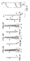
- the contact 10 has a rake end 12.
- the contact 14 has a knuckle end 16.
- the contact 18 has a pointed end 20.
- the contact or wiper 22, as shown in Fig. 1D, may also engage a mechanical strip 24 for support or for attachment purposes.
- the mechanical strip 24 may be electrically conductive or not, depending upon the desired application.
- Figs. 2A, 2B, and 2C correspond, respectively, to Figs. 1A, 1B. and 1C and show the arrangement of the carbon fiber bundles that are part of the composite material forming the specialized end constructions 12, 16, and 20, respectively. That is, the enlargement of Fig. 2A shows carbon fiber bundles 26 arranged in one layer forming the rake end 12. Similarly, bundles 28 and 30 respectively form knuckle end 16 and pointed end 20 in Figs. 2B and 2C, respectively. The other layers of the composite material are not shown because the structures of the carbon fiber bundles would be obscured.
- the contact or wiper element 40 is formed of a carbon fiber matrix, whose adjacent three carbon fiber layers 42, 44, 46 are essentially perpendicular to each other.
- the carbon fibers forming layers 42, 44, 46 are not bundled but are discretely placed-in a cross-hatching matrix, wherein the fibers in alternate layers may be parallel to each other, but those in adjacent layers are essentially nonparallel and may be perpendicular to each other.
- Fig. 4 shows a similarly constructed contact 50 in which the carbon fibers of only one layer 52 perform the actual contacting and an inner layer 54 and second outer layer provide structural support.
- the additional layers of the composite material are shown in Fig. 14.
- the matrix composition shown in the embodiments of Figs. 3 and 4 reinforces and strengthens the minuscule carbon fiber strands to provide support for retaining stable contact position.
- the carbon fiber strands may be continuous or discontinuous and the matrix need not necessarily be homogeneous.
- the matrix compositions of Figs. 3 and 4 can use an additional mechanical support strip, which can be electrically conductive depending upon the desired application.
- the carbon fibers of the matrix composition shown in Figs. 3 and 4 are firmly fixed in a very low resistance synthetic resin compound to restrict movement, add structural stability, and provide multidirectional electrical continuity.
- the planar form of a carbon fiber contact element 60 can consist of a single layer, not a matrix of carbon fiber strands, arranged in a horseshoe shape or upside-down U to provide a continuous, unbroken path from one end 62 of the carbon fiber element strands, one of which is shown typically at 64, to the other end 66, even though the carbon fiber strands may change direction by more than 90 degrees.
- each carbon fiber strand 64 will be both perpendicular and parallel to the resistive or conductive track, not shown, and each opposing end 62,66 of the continuous carbon fiber strands 64 will essentially contact different parallel resistive or conductive tracks, not shown.
- the horseshoe shaped contact 60 can employ a carrier, not shown, which can be electrically conductive or not, depending on the desired application.
- FIG. 6 A similar construction is shown in Fig. 6, wherein the contact 70 has a right-angle transition portion 72 in the path from one end 74 to the other end 76.
- a contact assembly 80 has a carbon fiber element formed as a very short strip 82 firmly and conductively attached at 84 by a conductive adhesive to a parallel portion 84 of a thin beam 86 composed of electrically conductive material.
- This beam construction provides a means for the current or voltage signal to flow unimpeded from the resistive or conductive track to the end terminus, thereby incorporating the compatible and desirable characteristics of the carbon fiber contact material with beam members formed of materials other than carbon fiber.
- the carbon fiber element 82 will be essentially perpendicular to the plane of the resistive or conductive track at all times.
- the planar form of the carbon fiber element consists of one or more parallel layers of carbon fiber strip arranged so that the free ends 12, 16, 20 of the carbon fiber elements 10, 14, 18, respectively, are designated as the ends that will contact the tracks of the resistive element or conductive element. It is a feature of the present invention that those ends 12, 16, 20 can he fabricated free of any other material, such as the low-resistance, synthetic resin compound or the like, for a length less than 3/16' (4.7625mm) to permit only the actual carbon fiber material to contact the respective tracks, thereby providing improved mating between the ends 12, 16, 20 of the contacts 10, 14, 18 and the tracks, not shown, of the respective conductive elements.
- the free end of the contact may remain parallel in the same plane or, as shown in Figs. 2A, 2B, and 2C, the free end may be bent or formed to an angle perpendicular to the primary length of the strip or formed into a knuckle shape depending upon the application.
- each contact or wiper element 90, 92, 94, respectively is fabricated in narrow strips of carbon fiber element, one of which is shown at 96, 98, 100, respectively, wherein each strip is less than 0.015'(0.3810mm) in width and is composed or one or more parallel strands of carbon fibers. A number of these strips are arranged in a single flat plane, with each strip being essentially parallel to, but not fused or chemically bonded to, each other.
- the multiple independent parallel strips are mechanically captured by respective collars 102, 104, 106, in a single plane and/or chemically bonded with a low-resistance, electrically conductive synthetic resin compound at one end of the assembled strips, so that the independent multiple strip sections will be electrically uniform in their output signal and also be receptive to further assembly operations.
- the free ends 108, 110, 112 of the respective multiple strip sections 90, 92, 94 that are to function as the intimate contact points with the track of the resistive or conductive element can remain coplanar to the strip or be formed as a rake as shown in Fig. 8, a knuckle as shown in Fig. 9, or other compatible contact geometry, such as the point as shown in Fig. 10.
- This feature permits the assembly to contain multiple contact strips, such as 96, 98, 100, each with relatively independent mechanical movement in a direction perpendicular to the resistive or conductive track of the substrate element.
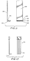
- Fig. 11 is an embodiment similar to that of Fig. 7 wherein multiple layers 120, 122, 124, of carbon fiber elements are attached to a shorter leg 126 of an L-shaped carrier 128.
- the carbon fibers in each layer 120, 122, 124 are substantially aligned to be parallel and the layers may be attached to the carrier by an electrically conductive synthetic resin compound shown generally at 130.
- the electrical contact devices are formed of multiple layers of carbon fibers in various alignments, Similarly, all other embodiments herein shown and described can be formed of multiple layers. So too, the various embodiments of the present invention can be used with a carrier that can be electrically conductive or not, depending upon the desired application.
- an electrical contact or wiper 140 can be formed of only a single carbon fiber element 142 that can be around 0.010' to 0.015' (0.2540 to 0.3810mm) in thickness.
- a rake end 144 is provided in this embodiment, any of the other end treatments described above are also appropriate.
- all of the embodiments described so far can be formed from a composite carbon fiber material that has as its core a carbon fiber structure that has carbon fiber bundles arranged in one layer, as in Figs. 2A-22C, or in multiple layers, as in Fig. 3.
- a layer of the carbon fiber bundles 150 has mats 152, 154 formed of nonwoven carbon fibers arranged on each flat side.
- a thermoplastic resin is applied to the exterior surfaces of the mats 152, 154. This thermoplastic resin, or polymer, completes the structure and bonds the mats 152, 154 to the carbon fiber bundle structure 150, thereby forming a stable composite material.
- the nonwoven carbon-fiber mat 152 or 154 is substantially isotropic and the fibers are so randomly arranged as to provide little or no directionality in the plane of the mat.
- the nonwoven carbon fiber mat provides a primary electrical current carrying capacity and also provides improved mechanical strength to the overall construction. More specifically, the nonwoven carbon fiber provides off-axis mechanical stability, as well as off-axis current carrying capability, where the off-axis term relates to a longitudinal direction of the finally manufactured electrical contact.
- the nonwoven carbon fiber mat is available commercially from Hollingsworth & Vose Company, East Walpole, Massachusetts and ranges in thickness from 0.08 mm to 0.79 mm.
- Fig. 14 is an end view of the assembled composite material 160 described above in which the nonwoven carbon fiber mats 152, 154 are arranged on the carbon fiber structure 150 and in which thermoplastic resin layer 162 is applied over the nonwoven carbon fiber layer 152 and a thermoplastic resin layer 164 is applied over the nonwoven carbon fiber mat 154.
- thermoplastic resin layer 162 is applied over the nonwoven carbon fiber layer 152
- thermoplastic resin layer 164 is applied over the nonwoven carbon fiber mat 154.
Landscapes
- Non-Insulated Conductors (AREA)
- Conductive Materials (AREA)
- Inorganic Fibers (AREA)
- Laminated Bodies (AREA)
- Nonwoven Fabrics (AREA)
- Contacts (AREA)
Priority Applications (4)
| Application Number | Priority Date | Filing Date | Title |
|---|---|---|---|
| DE60228981T DE60228981D1 (de) | 2002-12-19 | 2002-12-19 | Elektrische Kohlenstofffaserkontakte aus Kohlenstofffaserverbundmaterial |
| AT02394117T ATE408910T1 (de) | 2002-12-19 | 2002-12-19 | Elektrische kohlenstofffaserkontakte aus kohlenstofffaserverbundmaterial |
| EP02394117A EP1432085B1 (fr) | 2002-12-19 | 2002-12-19 | Contacts èlectriques en fibre de carbone formès avec du matériel en fibre de carbone composite |
| ES02394117T ES2312540T3 (es) | 2002-12-19 | 2002-12-19 | Contactos electricos de fibra de carbono formados con material compuesto de fibra de carbono. |
Applications Claiming Priority (1)
| Application Number | Priority Date | Filing Date | Title |
|---|---|---|---|
| EP02394117A EP1432085B1 (fr) | 2002-12-19 | 2002-12-19 | Contacts èlectriques en fibre de carbone formès avec du matériel en fibre de carbone composite |
Publications (2)
| Publication Number | Publication Date |
|---|---|
| EP1432085A1 true EP1432085A1 (fr) | 2004-06-23 |
| EP1432085B1 EP1432085B1 (fr) | 2008-09-17 |
Family
ID=32338225
Family Applications (1)
| Application Number | Title | Priority Date | Filing Date |
|---|---|---|---|
| EP02394117A Expired - Lifetime EP1432085B1 (fr) | 2002-12-19 | 2002-12-19 | Contacts èlectriques en fibre de carbone formès avec du matériel en fibre de carbone composite |
Country Status (4)
| Country | Link |
|---|---|
| EP (1) | EP1432085B1 (fr) |
| AT (1) | ATE408910T1 (fr) |
| DE (1) | DE60228981D1 (fr) |
| ES (1) | ES2312540T3 (fr) |
Cited By (2)
| Publication number | Priority date | Publication date | Assignee | Title |
|---|---|---|---|---|
| WO2014099566A1 (fr) * | 2012-12-20 | 2014-06-26 | 3M Innovative Properties Company | Connecteurs électriques et procédés permettant de fabriquer ces derniers |
| DE102014222265A1 (de) * | 2014-10-31 | 2016-05-04 | Schunk Wien Gesellschaft M.B.H. | Ableitungseinrichtung |
Citations (3)
| Publication number | Priority date | Publication date | Assignee | Title |
|---|---|---|---|---|
| US4460633A (en) * | 1981-12-16 | 1984-07-17 | Kurashiki Boseki Kabushiki Kaisha | Non-woven reinforcement for composite |
| US6444102B1 (en) * | 2000-02-07 | 2002-09-03 | Micro Contacts Inc. | Carbon fiber electrical contacts |
| US20030008125A1 (en) * | 2001-07-05 | 2003-01-09 | Curt Delanoy | Composite carbon fiber material and method of making same |
-
2002
- 2002-12-19 AT AT02394117T patent/ATE408910T1/de not_active IP Right Cessation
- 2002-12-19 EP EP02394117A patent/EP1432085B1/fr not_active Expired - Lifetime
- 2002-12-19 ES ES02394117T patent/ES2312540T3/es not_active Expired - Lifetime
- 2002-12-19 DE DE60228981T patent/DE60228981D1/de not_active Expired - Lifetime
Patent Citations (3)
| Publication number | Priority date | Publication date | Assignee | Title |
|---|---|---|---|---|
| US4460633A (en) * | 1981-12-16 | 1984-07-17 | Kurashiki Boseki Kabushiki Kaisha | Non-woven reinforcement for composite |
| US6444102B1 (en) * | 2000-02-07 | 2002-09-03 | Micro Contacts Inc. | Carbon fiber electrical contacts |
| US20030008125A1 (en) * | 2001-07-05 | 2003-01-09 | Curt Delanoy | Composite carbon fiber material and method of making same |
Cited By (4)
| Publication number | Priority date | Publication date | Assignee | Title |
|---|---|---|---|---|
| WO2014099566A1 (fr) * | 2012-12-20 | 2014-06-26 | 3M Innovative Properties Company | Connecteurs électriques et procédés permettant de fabriquer ces derniers |
| DE102014222265A1 (de) * | 2014-10-31 | 2016-05-04 | Schunk Wien Gesellschaft M.B.H. | Ableitungseinrichtung |
| DE102014222265B4 (de) * | 2014-10-31 | 2016-07-21 | Schunk Wien Gesellschaft M.B.H. | Ableitungseinrichtung |
| US10660188B2 (en) | 2014-10-31 | 2020-05-19 | Schunk Wien Gesellschaft M.B.H. | Electrostatic discharging device |
Also Published As
| Publication number | Publication date |
|---|---|
| ATE408910T1 (de) | 2008-10-15 |
| ES2312540T3 (es) | 2009-03-01 |
| DE60228981D1 (de) | 2008-10-30 |
| EP1432085B1 (fr) | 2008-09-17 |
Similar Documents
| Publication | Publication Date | Title |
|---|---|---|
| US6444102B1 (en) | Carbon fiber electrical contacts | |
| US4003621A (en) | Electrical connector employing conductive rectilinear elements | |
| US5984690A (en) | Contactor with multiple redundant connecting paths | |
| US5185683A (en) | Suspension arm mounting assembly | |
| US4191445A (en) | Louvered electrical connector | |
| JP4445004B2 (ja) | 電気装置 | |
| US8398413B2 (en) | Carbon fiber electrical contacts formed of composite material including plural carbon fiber elements bonded together in low-resistance synthetic resin | |
| EP1432085B1 (fr) | Contacts èlectriques en fibre de carbone formès avec du matériel en fibre de carbone composite | |
| GB2159007A (en) | Anisotropic connectors for connecting printed circuit boards | |
| KR100776851B1 (ko) | 탄소 섬유 복합 재료로 형성된 탄소 섬유 전기적 콘택을 포함하는 전기 장치 | |
| US20060176143A1 (en) | Potentiometer | |
| US7344411B2 (en) | Electrical connector and method of fabricating the same | |
| JPH1140292A (ja) | 電気接続部材 | |
| JP4289762B2 (ja) | 電気コネクタ | |
| JPH10223290A (ja) | 接続用端子 | |
| US20040000985A1 (en) | Sliding-type electric component including carbon fiber contact | |
| US11242473B2 (en) | Electrically conductive adhesive film and producing method thereof | |
| EP1487059A1 (fr) | Bloc conducteur anisotrope et son procede de production | |
| US6080267A (en) | Method of electroconductive fastening of current collectors and terminals in electrochemical devices | |
| JP5048665B2 (ja) | 可変抵抗器 | |
| JP7574120B2 (ja) | トルクセンサ | |
| JP2004031688A (ja) | 摺動接点と摺動型電気部品及びセンサ | |
| US3291935A (en) | Thermostat actuators of resinous material | |
| JP4729211B2 (ja) | 表面実装用抵抗器及びその製造方法 | |
| JPH0432723Y2 (fr) |
Legal Events
| Date | Code | Title | Description |
|---|---|---|---|
| PUAI | Public reference made under article 153(3) epc to a published international application that has entered the european phase |
Free format text: ORIGINAL CODE: 0009012 |
|
| AK | Designated contracting states |
Kind code of ref document: A1 Designated state(s): AT BE BG CH CY CZ DE DK EE ES FI FR GB GR IE IT LI LU MC NL PT SE SI SK TR |
|
| AX | Request for extension of the european patent |
Extension state: AL LT LV MK RO |
|
| 17P | Request for examination filed |
Effective date: 20041223 |
|
| AKX | Designation fees paid |
Designated state(s): AT BE BG CH CY CZ DE DK EE ES FI FR GB GR IE IT LI LU MC NL PT SE SI SK TR |
|
| 17Q | First examination report despatched |
Effective date: 20070417 |
|
| GRAP | Despatch of communication of intention to grant a patent |
Free format text: ORIGINAL CODE: EPIDOSNIGR1 |
|
| GRAS | Grant fee paid |
Free format text: ORIGINAL CODE: EPIDOSNIGR3 |
|
| RTI1 | Title (correction) |
Free format text: CARBON FIBER ELECTRICAL CONTACTS FORMED OF COMPOSITE CARBON FIBER MATERIAL |
|
| GRAA | (expected) grant |
Free format text: ORIGINAL CODE: 0009210 |
|
| AK | Designated contracting states |
Kind code of ref document: B1 Designated state(s): AT BE BG CH CY CZ DE DK EE ES FI FR GB GR IE IT LI LU MC NL PT SE SI SK TR |
|
| REG | Reference to a national code |
Ref country code: GB Ref legal event code: FG4D |
|
| REG | Reference to a national code |
Ref country code: CH Ref legal event code: EP |
|
| REG | Reference to a national code |
Ref country code: IE Ref legal event code: FG4D |
|
| REF | Corresponds to: |
Ref document number: 60228981 Country of ref document: DE Date of ref document: 20081030 Kind code of ref document: P |
|
| PG25 | Lapsed in a contracting state [announced via postgrant information from national office to epo] |
Ref country code: AT Free format text: LAPSE BECAUSE OF FAILURE TO SUBMIT A TRANSLATION OF THE DESCRIPTION OR TO PAY THE FEE WITHIN THE PRESCRIBED TIME-LIMIT Effective date: 20080917 Ref country code: FI Free format text: LAPSE BECAUSE OF FAILURE TO SUBMIT A TRANSLATION OF THE DESCRIPTION OR TO PAY THE FEE WITHIN THE PRESCRIBED TIME-LIMIT Effective date: 20080917 Ref country code: SI Free format text: LAPSE BECAUSE OF FAILURE TO SUBMIT A TRANSLATION OF THE DESCRIPTION OR TO PAY THE FEE WITHIN THE PRESCRIBED TIME-LIMIT Effective date: 20080917 |
|
| REG | Reference to a national code |
Ref country code: ES Ref legal event code: FG2A Ref document number: 2312540 Country of ref document: ES Kind code of ref document: T3 |
|
| NLV1 | Nl: lapsed or annulled due to failure to fulfill the requirements of art. 29p and 29m of the patents act | ||
| PG25 | Lapsed in a contracting state [announced via postgrant information from national office to epo] |
Ref country code: BE Free format text: LAPSE BECAUSE OF FAILURE TO SUBMIT A TRANSLATION OF THE DESCRIPTION OR TO PAY THE FEE WITHIN THE PRESCRIBED TIME-LIMIT Effective date: 20080917 |
|
| PG25 | Lapsed in a contracting state [announced via postgrant information from national office to epo] |
Ref country code: BG Free format text: LAPSE BECAUSE OF FAILURE TO SUBMIT A TRANSLATION OF THE DESCRIPTION OR TO PAY THE FEE WITHIN THE PRESCRIBED TIME-LIMIT Effective date: 20081217 |
|
| PG25 | Lapsed in a contracting state [announced via postgrant information from national office to epo] |
Ref country code: PT Free format text: LAPSE BECAUSE OF FAILURE TO SUBMIT A TRANSLATION OF THE DESCRIPTION OR TO PAY THE FEE WITHIN THE PRESCRIBED TIME-LIMIT Effective date: 20090217 Ref country code: NL Free format text: LAPSE BECAUSE OF FAILURE TO SUBMIT A TRANSLATION OF THE DESCRIPTION OR TO PAY THE FEE WITHIN THE PRESCRIBED TIME-LIMIT Effective date: 20080917 |
|
| PLBE | No opposition filed within time limit |
Free format text: ORIGINAL CODE: 0009261 |
|
| STAA | Information on the status of an ep patent application or granted ep patent |
Free format text: STATUS: NO OPPOSITION FILED WITHIN TIME LIMIT |
|
| PG25 | Lapsed in a contracting state [announced via postgrant information from national office to epo] |
Ref country code: DK Free format text: LAPSE BECAUSE OF FAILURE TO SUBMIT A TRANSLATION OF THE DESCRIPTION OR TO PAY THE FEE WITHIN THE PRESCRIBED TIME-LIMIT Effective date: 20080917 Ref country code: MC Free format text: LAPSE BECAUSE OF NON-PAYMENT OF DUE FEES Effective date: 20081231 Ref country code: EE Free format text: LAPSE BECAUSE OF FAILURE TO SUBMIT A TRANSLATION OF THE DESCRIPTION OR TO PAY THE FEE WITHIN THE PRESCRIBED TIME-LIMIT Effective date: 20080917 |
|
| REG | Reference to a national code |
Ref country code: CH Ref legal event code: PL |
|
| 26N | No opposition filed |
Effective date: 20090618 |
|
| PG25 | Lapsed in a contracting state [announced via postgrant information from national office to epo] |
Ref country code: LI Free format text: LAPSE BECAUSE OF NON-PAYMENT OF DUE FEES Effective date: 20081231 Ref country code: CH Free format text: LAPSE BECAUSE OF NON-PAYMENT OF DUE FEES Effective date: 20081231 |
|
| PG25 | Lapsed in a contracting state [announced via postgrant information from national office to epo] |
Ref country code: SE Free format text: LAPSE BECAUSE OF FAILURE TO SUBMIT A TRANSLATION OF THE DESCRIPTION OR TO PAY THE FEE WITHIN THE PRESCRIBED TIME-LIMIT Effective date: 20081217 |
|
| PG25 | Lapsed in a contracting state [announced via postgrant information from national office to epo] |
Ref country code: CY Free format text: LAPSE BECAUSE OF FAILURE TO SUBMIT A TRANSLATION OF THE DESCRIPTION OR TO PAY THE FEE WITHIN THE PRESCRIBED TIME-LIMIT Effective date: 20080917 Ref country code: LU Free format text: LAPSE BECAUSE OF NON-PAYMENT OF DUE FEES Effective date: 20081219 |
|
| PG25 | Lapsed in a contracting state [announced via postgrant information from national office to epo] |
Ref country code: TR Free format text: LAPSE BECAUSE OF FAILURE TO SUBMIT A TRANSLATION OF THE DESCRIPTION OR TO PAY THE FEE WITHIN THE PRESCRIBED TIME-LIMIT Effective date: 20080917 |
|
| PG25 | Lapsed in a contracting state [announced via postgrant information from national office to epo] |
Ref country code: GR Free format text: LAPSE BECAUSE OF FAILURE TO SUBMIT A TRANSLATION OF THE DESCRIPTION OR TO PAY THE FEE WITHIN THE PRESCRIBED TIME-LIMIT Effective date: 20081218 |
|
| REG | Reference to a national code |
Ref country code: FR Ref legal event code: PLFP Year of fee payment: 13 |
|
| REG | Reference to a national code |
Ref country code: FR Ref legal event code: PLFP Year of fee payment: 14 |
|
| REG | Reference to a national code |
Ref country code: FR Ref legal event code: PLFP Year of fee payment: 15 |
|
| PGFP | Annual fee paid to national office [announced via postgrant information from national office to epo] |
Ref country code: CZ Payment date: 20161219 Year of fee payment: 15 Ref country code: SK Payment date: 20161216 Year of fee payment: 15 Ref country code: IE Payment date: 20161219 Year of fee payment: 15 Ref country code: GB Payment date: 20161220 Year of fee payment: 15 |
|
| PGFP | Annual fee paid to national office [announced via postgrant information from national office to epo] |
Ref country code: ES Payment date: 20161227 Year of fee payment: 15 Ref country code: FR Payment date: 20161229 Year of fee payment: 15 |
|
| PGFP | Annual fee paid to national office [announced via postgrant information from national office to epo] |
Ref country code: DE Payment date: 20161230 Year of fee payment: 15 |
|
| PGFP | Annual fee paid to national office [announced via postgrant information from national office to epo] |
Ref country code: IT Payment date: 20161229 Year of fee payment: 15 |
|
| REG | Reference to a national code |
Ref country code: DE Ref legal event code: R119 Ref document number: 60228981 Country of ref document: DE |
|
| PG25 | Lapsed in a contracting state [announced via postgrant information from national office to epo] |
Ref country code: CZ Free format text: LAPSE BECAUSE OF NON-PAYMENT OF DUE FEES Effective date: 20171219 |
|
| GBPC | Gb: european patent ceased through non-payment of renewal fee |
Effective date: 20171219 |
|
| REG | Reference to a national code |
Ref country code: SK Ref legal event code: MM4A Ref document number: E 4555 Country of ref document: SK Effective date: 20171219 |
|
| REG | Reference to a national code |
Ref country code: IE Ref legal event code: MM4A |
|
| REG | Reference to a national code |
Ref country code: FR Ref legal event code: ST Effective date: 20180831 |
|
| PG25 | Lapsed in a contracting state [announced via postgrant information from national office to epo] |
Ref country code: FR Free format text: LAPSE BECAUSE OF NON-PAYMENT OF DUE FEES Effective date: 20180102 Ref country code: IE Free format text: LAPSE BECAUSE OF NON-PAYMENT OF DUE FEES Effective date: 20171219 Ref country code: DE Free format text: LAPSE BECAUSE OF NON-PAYMENT OF DUE FEES Effective date: 20180703 Ref country code: IT Free format text: LAPSE BECAUSE OF NON-PAYMENT OF DUE FEES Effective date: 20171219 |
|
| PG25 | Lapsed in a contracting state [announced via postgrant information from national office to epo] |
Ref country code: SK Free format text: LAPSE BECAUSE OF NON-PAYMENT OF DUE FEES Effective date: 20171219 Ref country code: GB Free format text: LAPSE BECAUSE OF NON-PAYMENT OF DUE FEES Effective date: 20171219 |
|
| REG | Reference to a national code |
Ref country code: ES Ref legal event code: FD2A Effective date: 20190703 |
|
| PG25 | Lapsed in a contracting state [announced via postgrant information from national office to epo] |
Ref country code: ES Free format text: LAPSE BECAUSE OF NON-PAYMENT OF DUE FEES Effective date: 20171220 |