EP1432130A1 - Dekodiervorrichtung und dekodierverfahren - Google Patents
Dekodiervorrichtung und dekodierverfahren Download PDFInfo
- Publication number
- EP1432130A1 EP1432130A1 EP03791297A EP03791297A EP1432130A1 EP 1432130 A1 EP1432130 A1 EP 1432130A1 EP 03791297 A EP03791297 A EP 03791297A EP 03791297 A EP03791297 A EP 03791297A EP 1432130 A1 EP1432130 A1 EP 1432130A1
- Authority
- EP
- European Patent Office
- Prior art keywords
- decoding
- distribution
- message
- determining
- quantization width
- Prior art date
- Legal status (The legal status is an assumption and is not a legal conclusion. Google has not performed a legal analysis and makes no representation as to the accuracy of the status listed.)
- Ceased
Links
Images





Classifications
-
- H—ELECTRICITY
- H03—ELECTRONIC CIRCUITRY
- H03M—CODING; DECODING; CODE CONVERSION IN GENERAL
- H03M13/00—Coding, decoding or code conversion, for error detection or error correction; Coding theory basic assumptions; Coding bounds; Error probability evaluation methods; Channel models; Simulation or testing of codes
- H03M13/65—Purpose and implementation aspects
- H03M13/6577—Representation or format of variables, register sizes or word-lengths and quantization
-
- H—ELECTRICITY
- H03—ELECTRONIC CIRCUITRY
- H03M—CODING; DECODING; CODE CONVERSION IN GENERAL
- H03M13/00—Coding, decoding or code conversion, for error detection or error correction; Coding theory basic assumptions; Coding bounds; Error probability evaluation methods; Channel models; Simulation or testing of codes
- H03M13/03—Error detection or forward error correction by redundancy in data representation, i.e. code words containing more digits than the source words
- H03M13/05—Error detection or forward error correction by redundancy in data representation, i.e. code words containing more digits than the source words using block codes, i.e. a predetermined number of check bits joined to a predetermined number of information bits
- H03M13/11—Error detection or forward error correction by redundancy in data representation, i.e. code words containing more digits than the source words using block codes, i.e. a predetermined number of check bits joined to a predetermined number of information bits using multiple parity bits
- H03M13/1102—Codes on graphs and decoding on graphs, e.g. low-density parity check [LDPC] codes
- H03M13/1105—Decoding
- H03M13/1111—Soft-decision decoding, e.g. by means of message passing or belief propagation algorithms
Definitions
- the present invention relates to a decoding device and a decoding method for decoding of low-density parity check codes.
- PCCC parallel concatenated convolutional codes
- SCCC serially concatenated convolutional codes
- LDPC codes low-density parity check codes
- the LDPC codes were first proposed by R. G. Gallager in R. G. Gallager, "Low-Density Parity-Check Codes", Cambridge, Massachusetts: M. I. T. Press, 1963, and were rediscovered in D. J. C. MacKay, "Good error correcting codes based on very sparse matrices", submitted to IEEE Trans. Inf. Theory, IT-45, pp. 399-431, 1999; M. G. Luby, M. Mitzenraum, M. A. Shokrollahi, and D. A. Spielman, "Analysis of low density codes and improved designs using irregular graphs", available at http://www.icsi.berkeley.edu/-luby/; and so forth.
- the LDPC codes will be described hereinbelow in detail.
- the LDPC codes are linear codes, and are not necessarily binary; however, the following description will be made in the context of binary LDPC codes.
- the sparse matrix means that the number of "1s" in this matrix is very small, and may be, for example, a sparse check matrix represented by "H", shown in Fig. 14, of which the Hamming weight of each column is 3 and the Hamming weight of each row is 6.
- the LDPC codes defined by the check matrix H of which the Hamming weights of each row and column are constant are referred to as regular LDPC codes.
- the LDPC codes defined by the check matrix H of which the Hamming weights of each row and column are not constant are referred to as irregular LDPC codes.
- the codeword generated by the encoder is mapped so that a code bit of value "0" is converted into “+1” and a code bit of value "1” is converted into “-1” for transmission.
- the transmitted codeword is received by a decoder via a predetermined communication channel.
- Decoding of the LDPC codes can be implemented by the "Probabilistic Decoding” algorithm proposed by Gallager described above, which is a message-passing algorithm based on belief propagation operating on a so-called Tanner graph consisting of variable nodes (also referred to as message nodes) and check nodes.
- the "Probabilistic Decoding” however, messages exchanged among the nodes are real numbers, and it is therefore necessary to monitor the probability distribution itself of the messages of sequential numbers in order to analytically solve the messages. Thus, very difficult analysis is required.
- Gallager has proposed algorithm A or algorithm B as an algorithm for decoding LDPC codes.
- decoding of LDPC codes is performed according to the procedure shown in Fig. 15.
- the received value is represented by U 0 (u 0i )
- the message output from a check node is represented by u j
- the message output from a variable node is represented by v i .
- Each message is a real number whose "0" likelihood is expressed by the so-called log likelihood ratio.
- step S11 upon reception of the received value U 0 (u 0i ), the message u j is set to "0" and an integer k of an iterative decoding counter is also set to "0".
- step S12 the message v i is determined by computation given by Eq. (1) below based on the received value U 0 (u 0i ), and the message u j is determined by computation given by Eq. (2) below based on the determined message v i . Then, in the decoding of LDPC codes, the integer k is incremented by "1".
- dv and dc are arbitrarily selectable parameters representing the number of "1s" in the vertical direction (column) and the horizontal direction (row) of the check matrix H described above, respectively.
- the messages input from edges that are to output the messages are not used as product or sum parameters, and the product or sum ranges are up to dv-1 and dc-1.
- the computation given by Eq. (2) is performed by preparing in advance a table of functions R given by Eq.
- step S13 it is determined whether or not the integer k is greater than N.
- step S12 if it is determined that the integer k is not greater than N, the processing from step S12 is repeated; if it is determined that the integer k is greater than N, the process proceeds to step S14.
- step S14 the message v i as a decoding result to be finally output is determined by computation given by Eq. (5) below, and the result is output. Then, the series of processing steps ends. Unlike Eq. (1), Eq. (5) below is calculated using the messages input from all connected edges.
- a received value In the decoding of LDPC codes, a received value must be initially quantized. In a case where the received value or a message exchanged between nodes is expressed with a low bit number, it is known that the performance changes depending upon the setting of the quantization width.
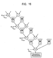
- decoding of LDPC codes for a low bit number is performed according to the procedure shown in Fig. 17.
- step S21 upon reception of the received value U 0 (u 0i ), the received value U 0 (u 0i ) is quantized with a low bit number, the message v i is set to "u 0i ", and an integer k of an iterative decoding counter is set to "0".
- the received value U 0 (u 0i ) is quantized to 3 bits.
- the received value U 0 (u 0i ) quantized to 3 bits is then quantized to 2 bits for use in determining the message v i .
- step S22 the message u j is determined based on the message v i , and the message v i is further determined based on the received value U 0 (u 0i ) and the determined message u j by computation given by Eq. (1). Then, in the decoding of LDPC codes, the integer k is incremented by "1".
- a table of single-output functions of low bit number is produced from two low-bit inputs v 1 and v 2 in advance, and this table is iteratively used to determine the low-bit message u j .
- the message v i which is determined using Eq. (1), causes the bit number to increase, and therefore quantization to 2 bits is performed.
- step S23 it is determined whether or not the integer k is greater than N.
- step S22 if it is determined that the integer k is not greater than N, the processing from step S22 is repeated; if it is determined that the integer k is greater than N, the process proceeds to step S24.
- step S24 the message v i to be finally output as a result of decoding is determined, and the result is output. Then, the series of processing steps ends.
- the performance changes depending upon the quantization width for quantization of a received value and messages exchanged between nodes. Furthermore, in the decoding of LDPC codes, the quantization width for determination of the message v i using Eq. (1) also affects the error correction performance.
- the present invention has been made in view of such a situation, and it is an object of the present invention to provide a decoding device and a decoding method that optimize the quantization width to improve the code performance, thus allowing for high-precision decoding of LDPC codes.
- a decoding device that decodes a code encoded by low-density parity check coding, including receiving means for receiving data as a received value, distribution determining means for determining a distribution of noise that is superposed on the data received by the receiving means, quantization width determining means that determines a quantization width that is optimized so that an error probability after decoding becomes the minimum with respect to the noise distribution determined by the distribution determining means or the noise distribution determined by the distribution determining means becomes the maximum with respect to a given error probability after decoding, quantizing means for quantizing a probability distribution of the received value received by the receiving means with a predetermined low bit number according to the quantization width determined by the quantization width determining means, and message determining means for determining a message as information bits based on the probability distribution of the received value quantized by the quantizing means.
- the probability distribution of the received value is quantized by the quantizing means with a predetermined low bit number according to the quantization width that is optimized so that the error probability after decoding becomes the minimum with respect to a given noise distribution or the noise distribution becomes the maximum with respect to a given error probability after decoding, and decoding is performed by the message determining means based on the probability distribution of the received value quantized by the quantizing means.
- a decoding method is a decoding method for decoding a code encoded by low-density parity check coding, including a receiving step of receiving data as a received value, a distribution determining step of determining a distribution of noise that is superposed on the data received in the receiving step, a quantization width determining step of determining a quantization width that is optimized so that an error probability after decoding becomes the minimum with respect to the noise distribution determined in the distribution determining step or the noise distribution determined in the distribution determining step becomes the maximum with respect to a given error probability after decoding, a quantizing step of quantizing a probability distribution of the received value received in the receiving step with a predetermined low bit number according to the quantization width determined in the quantization width determining step, and a message determining step of determining a message as information bits based on the probability distribution of the received value quantized in the quantizing step.
- the probability distribution of the received value is quantized with a predetermined low bit number according to the quantization width that is optimized so that the error probability after decoding becomes the minimum with respect to a given noise distribution or the noise distribution becomes the maximum with respect to a given error probability after decoding, and decoding is performed based on the quantized probability distribution of the received value.
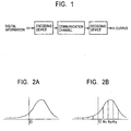
- this embodiment provides a data transmission and reception system implemented by a communication model for encoding digital information by an encoding device 1 of a transmitting apparatus (not shown) and inputting the digital information output from the encoding device 1 to a receiving apparatus (not shown) via a predetermined noisy communication channel 2 to decode the digital information by a decoding device 3 of this receiving apparatus.
- the encoding device 1 performs coding of low-density parity check codes (hereinafter referred to as LDPC codes).
- LDPC codes low-density parity check codes
- the encoding device 1 is capable of optimizing the degree sequence, as described below, when the decoding device 3 expresses a received value and messages exchanged between nodes with a low bit number, thus allowing for an improvement in code performance.
- the decoding device 3 performs decoding of codes encoded by the encoding device 1 and performs iterative decoding.
- the decoding device 3 is capable of optimizing the quantization width for expressing a received value and messages exchanged between nodes with a low bit number, thus allowing for high-precision decoding of LDPC codes.
- V the message output from a variable node
- U the message output from a check node
- message U 0 is an initial message
- the message U is given by Eq. (7) as follows:
- a positive probability distribution and a negative probability distribution of the initial message are each divided into four regions. That is, in the case of the probability distribution of the initial message shown in Fig. 2A, quantization is performed so that the probability distribution is divided into eight regions, as shown in Fig. 2B.
- the x-axis indicates the log likelihood ratio and the y-axis indicates the probability.
- the log likelihood ratio is divided at three points in the positive portion, and these values, i.e., the quantization widths, are represented by a 1 , a 2 , and a 3 . Division in the negative portion is symmetric to that in the positive portion.
- the message U 0 is 3 bits with values 0 to 7, and the messages U j other than the initial message U 0 are each 2 bits with values 0 to 3.
- the convolutional computation give by Eq. (8) is implemented like polynomial multiplication.
- the determined probability distribution P v has values 0 to 13.
- the message represented by the probability distribution P v is quantized to 2 bits to produce a message V to be output from a variable node.
- variable node is the 5-input single-output node.
- the message V i output from this variable node is 2 bits with values 0 to 3.
- the values 0 and 1 are associated with negative log-likelihood ratio values, and the values 2 and 3 are associated with positive log-likelihood ratio values.
- the variable node outputs value "0" or "1” when the input messages contain an odd number of "0s" or “1s", and output value "2" or "3" when the input messages contain an even number of "0s" or "1s”.
- the variable node outputs value "1" or "2".
- the 2-bit message V 3 is determined by referring to a table, e.g., Table 1 below, which is produced in advance: Conversion Table for Eq. (9) V 2 0 1 2 3 V 1 0 3 2 1 0 1 2 2 1 1 2 1 1 2 2 3 0 1 2 3
- Example analyses using the density evolution described above will now be shown. Analyses are performed for a 3-bit initial message U 0 in a case where the quantization widths a 1 , a 2 , and a 3 are optimized and in a case where the quantization widths a 1 , a 2 , and a 3 are arranged with equal intervals, and an analysis is performed for a 2-bit initial message U 0 in a case where only the quantization width a 1 is optimized.
- an analysis is performed in a case where the quantization widths a 1 , a 2 , and a 3 are optimized when the initial message U 0 is 3 bits.
- the computation is performed in a range of the log likelihood ratio from -25 to +25.
- the quantization widths a 1 , a 2 , and a 3 must be set as required.
- the quantization widths a 1 , a 2 , and a 3 are optimized so as to provide the best error correction performance.
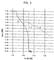
- the curve indicated by a solid line "a" shown in Fig. 3 is obtained.
- the x-axis indicates the signal-to-noise power ratio E b /N 0
- the y-axis indicates the base-10 logarithm of the error probability after decoding (log 10 BER).
- the noise distribution ⁇ and the error probability P b before error correction with respect to the signal-to-noise power ratio E b /N 0 on the x-axis are shown in Table 2 as follows: Relationship between E b /N 0 , ⁇ , and P b E b /N 0 1.50 2.00 2.50 3.00 ⁇ 0.8414 0.7943 0.7499 0.7080 P b 0.1173 0.1040 0.0912 0.0789
- the threshold of the noise distribution ⁇ is unclear. More specifically, when the noise distribution ⁇ is 0.8237, the error probability P b before error correction is 0.1123, and the error probability after error correction is reduced to 0.004533, but is not reduced to 0.
- the quantization widths a 1 , a 2 , and a 3 are 1.46, 2.91, and 4.57, respectively.
- the quantization widths a 1 , a 2 , and a 3 have substantially the same intervals therebetween, and the relationship given by Eq. (16) is determined as follows:
- the quantization widths a 1 , a 2 , and a 3 are 1.75, 8.02, and 21.6, respectively.
- the probability distribution P v given by Eq. (8) has values from 0 to 13, as described above, and is quantized to 2 bits using Eq. (17) as follows:
- the quantization width a 1 is 1.755.
- the initial message or the message output from the variable node is quantized using the quantization width that is set so that the error probability after decoding becomes the minimum with respect to a given noise distribution ⁇ .
- the quantization width is set so that the noise distribution ⁇ becomes the maximum with respect to a given error probability after decoding.
- the decoding device 3 of the receiving apparatus in the data transmission and reception system may be configured in the manner described below.
- the decoding device 3 includes a receiving unit 10 that receives data D1 sent from the transmitting apparatus via the communication channel 2, a distribution determining unit 20 that determines distribution ⁇ of noise that is superposed on the data D1 received by the receiving unit 10, a quantization width determining unit 30 that determines the quantization width that is optimized based on the noise distribution ⁇ determined by the distribution determining unit 20, a quantizing unit 40 that quantizes the probability distribution P u0 of the received value received by the receiving unit 10, and a message determining unit 50 that determines a message as information bits based on the probability distribution P u0 of the received value quantized by the quantizing unit 40.
- the decoding device 3 estimates the data input to the encoding device 1 based on the received value that takes a real value due to noise caused on the communication channel 2, and outputs decoded data D2.
- the receiving unit 10 receives as a received value the data D1 sent from the transmitting apparatus via the communication channel 2.
- the receiving unit 10 supplies the received value to the distribution determining unit 20 and the quantizing unit 40.
- the distribution determining unit 20 determines distribution ⁇ of noise that is superposed on the data D1 received by the receiving unit 10.
- the distribution determining unit 20 supplies information indicating the value of the determined noise distribution ⁇ to the quantization width determining unit 30.
- the quantization width determining unit 30 determines the optimum quantization width based on the noise distribution ⁇ determined by the distribution determining unit 20. That is, the quantization width determining unit 30 determines the quantization width so that the error probability after decoding becomes the minimum with respect to the noise distribution ⁇ determined by the distribution determining unit 20. Alternatively, the quantization width determining unit 30 may determine the quantization width so that the noise distribution ⁇ becomes the maximum with respect to a given error probability after decoding.
- the quantization width determining unit 30 supplies information indicating the value of the quantization width determined for the received value to the quantizing unit 40, and also supplies information indicating the value of the quantization width determined for the message output from the variable node to the message determining unit 50.
- the quantizing unit 40 quantizes the probability distribution P u0 of the received value received by the receiving unit 10 according to a predetermined low bit number. For example, when the message is to be expressed with 2 bits, the quantizing unit 40 quantizes the probability distribution P u0 of the received value to 3 bits. The quantizing unit 40 performs the quantization using the quantization width determined by the quantization width determining unit 30. The quantizing unit 40 supplies the quantized received value to the message determining unit 50.
- the message determining unit 50 iterates a series of decoding operations a predetermined number of times in which the message to be output from a variable node is determined based on the received value supplied from the quantizing unit 40 and the message to be output from a check node is also determined based on the determined message, thereby determining a message as information bits. More specifically, the message determining unit 50 determines the message by a series of steps shown in Fig. 5.
- step S1 the probability distribution P u0 of the received value quantized by the quantizing unit 40 is further quantized by the message determining unit 50 to determine the probability distribution P v of the message v i to be output from a variable node, and the integer k of an iterative processing counter is set to "0".
- the message determining unit 50 quantizes the probability distribution P u0 of the received value, which has been quantized to, for example, 3 bits, to 2 bits to determine the probability distribution P v .
- step S2 the message determining unit 50 determines the probability distribution P u of the message u j output from a check node based on the probability distribution P v , and also determines the probability distribution P v of the message v i based on the probability distribution P u0 of the received value and the determined probability distribution P u of the message u j by performing the computation given by Eq. (8). Then, in the decoding of LDPC codes, the integer k is incremented by "1".
- the message determining unit 50 produces a table of single-output functions of low bit number from two low-bit inputs v 1 and v 2 in advance, and iteratively uses this table as given by Eq. (12) to determine the probability distribution P u of the low-bit message u j . Since the bit number increases if the probability distribution P v of the message v i is determined by Eq. (8), the message determining unit 50 quantizes it to 2 bits. The message determining unit 50 performs the quantization using the quantization width determined by the quantization width determining unit 30.
- step S3 the message determining unit 50 determines whether or not the integer k is greater than N.
- step S2 determines that the integer k is not greater than N
- the processing from step S2 is repeated; if it is determined that the integer k is greater than N, the process proceeds to step S4.
- step S4 the message determining unit 50 determines and outputs the message v i to be finally output as a result of decoding. Then, the series of processing steps ends.
- the message determining unit 50 outputs the message determined by the series of steps described above, as the decoded data D2, to an external device.
- the decoding device 3 performs iterative decoding of the data D1 encoded and sent by the encoding device 1, thus constantly improving the code characteristics with high decoding complexity, and outputs the decoded data D2 as a result of decoding a predetermined number of times.
- the quantization width determining unit 30 determines the quantization width so that the error probability after decoding becomes the minimum with respect to the noise distribution ⁇ determined by the distribution determining unit 20, and, using this determined quantization width of low bit number, the quantizing unit 40 quantizes the received value and the message determining unit 50 quantizes the message.
- the decoding device 3 improves the code performance and achieves high-precision decoding.
- a check matrix is defined by the so-called degree sequence.
- the degree sequence represents the distribution of "1s" in a check matrix.
- n i of the function ⁇ (x), which corresponds to dv, as described above, representing the number of "1s" in the vertical direction (column) of the check matrix of a regular LDPC code is only an odd number. This is because, if the order n i is an even number, the probability distribution P u in the convolutional computation given by Eq. (8) is an odd number, thus causing a value with a log likelihood ratio of 0, leading to an inability to quantize to 2 bits.
- the order m i of the function ⁇ (x), which corresponds to dc, as described above, representing the number of "1s" in the horizontal direction (row) of the check matrix of the regular LDPC code, is either an odd number or an even number.
- the function ⁇ (x) is expressed by a polynomial that is a sum of two terms, whose order n i is 3 and an arbitrary odd number n, as given by Eq. (20) below, and the function ⁇ (x) is also expressed by a polynomial that is a sum of two terms, as given by Eq. (21) below.
- the coefficient ⁇ (3) represents the proportion of three "1s" in the vertical direction (column) of the check matrix
- the coefficient ⁇ (n) represents the proportion of n "1s” in the vertical direction (column) of the check matrix.
- the coefficient ⁇ (m) represents the proportion of m "1s” in the horizontal direction (row) of the check matrix
- the coefficient ⁇ (m+1) represents the proportion of m+1 "1s" in the horizontal direction (row) of the check matrix.
- the relationship between the parameter dc(ave) and the error probability after decoding exhibits the result indicated by a solid line "a" shown in Fig. 6.
- the x-axis indicates the parameter dc(ave)
- the y-axis indicates the base-10 logarithm of the error probability after decoding (log 10 BER).
- the probability distribution P v is quantized to 2 bits using, in place of Eq. (17), V(1) and V(2) each of which is a sum of two terms in the probability distribution P v , as given by Eq. (24) as follows:
- the probability distribution P v is quantized to 2 bits using, as given by Eq. (24), V(1) and V(2) each of which is a sum of two terms in the probability distribution P v .
- the performance is superior with the use of a sum of three terms in the probability distribution P v , as each of V(1) and V(2), and the error probability after error correction becomes the minimum when the parameter dc(ave) is 7.61.
- irregular codes exhibit a greater improvement in performance than regular codes, and, in irregular codes, the performance increases as the highest order n of the function ⁇ (x) representing the degree sequence increases.
- the function ⁇ (x) is expressed by a polynomial that is a sum of two terms, i.e., where the degree sequence in the vertical direction (column) of the check matrix is expressed by Eq. (20), will be described.
- the degree sequence in the horizontal direction (row) of the check matrix is expressed by the function p(x) given by Eq. (21).
- the x n term may be subjected to convolutional computation using the fast Fourier transform (hereinafter referred to as FFT).
- FFT fast Fourier transform
- this result is quantized to 2 bits.
- the quantization to 2 bits using V(1) and V(2) in Eq. (17), each of which is not expressed by a single term but two or more terms provides a greater improvement in performance.
- An observation is made on the performance while varying the number of terms k for V(1) and V(2) during quantization.
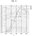
- the quantization widths a 1 , a 2 , and a 3 for quantization of the initial message U 0 to 3 bits are always optimized, and the noise distribution ⁇ with respect to error probability given by iterative decoding is determined. More specifically, in this analysis, given an order n of the function ⁇ (x), the coefficient ⁇ (n) given in Eq. (20) is optimized so that the noise distribution ⁇ becomes the maximum for the error probability after iterative decoding of 10 -3 and 10 -6 .
- Fig. 9 The relationship between the order n and the noise distribution ⁇ for the error probability after decoding of 10 -3 exhibits the results shown in Fig. 9.
- the coefficient ⁇ (n) is 0.3088, and the average ⁇ (ave) of the number of "1s" in the horizontal direction (row) of the check matrix is 8.1270.
- the coefficient ⁇ (n) is 0.3010, and the average ⁇ (ave) of the number of "1s" in the horizontal direction (row) of the check matrix is 8.096.
- the order n has a threshold that provides the best error correction performance.
- the order m of the function ⁇ (x) may be determined as an integer m that satisfies 0 ⁇ ⁇ (m) ⁇ 1.
- the probability distribution for the x 3 term is determined by Eqs. (8) and (17), and the x n1 and x n2 terms are subjected to convolutional computation using FFT.
- the best performance is exhibited when the coefficient ⁇ (n 1 ) is 0.
- the function ⁇ (x) is expressed by a polynomial that is a sum of two terms.
- the quantization widths a 1 , a 2 , and a 3 for quantization of the initial message Uo to 3 bits are 1.609, 5.542, and 24.124, respectively.
- the order n 1 has a threshold that provides the best error correction performance.
- the noise distribution ⁇ is not larger than the maximum noise distribution ⁇ when the function ⁇ (x) is expressed by a polynomial that is a sum of two terms.
- the degree sequence and the quantization width are set so that the error probability after decoding becomes the minimum with respect to a given noise distribution ⁇ .
- the degree sequence and the quantization width are set so that the noise distribution ⁇ becomes the maximum with respect to a given error probability after decoding.
- the function ⁇ (x) representing the degree sequence in the vertical direction (column) of the check matrix is optimized with respect to a given noise distribution ⁇ or a given error probability after decoding by fixing the order m i of the function ⁇ (x) representing the degree sequence in the horizontal direction (row) of the check matrix.
- the quantization widths a 1 , a 2 , and a 3 for quantization of the initial message are also optimized.
- the function ⁇ (x) may be expressed by a polynomial that is a sum of two terms whose orders are adjacent integers m and m+1, as give by Eq. (21).
- the average ⁇ (ave) of the number of "1s" in the horizontal direction (row) of the check matrix, the quantization widths a 1 , a 2 , and a 3 , and the function ⁇ (x) are optimized with respect to a given noise distribution ⁇ or a given error probability after decoding.
- each of the functions ⁇ (x) and ⁇ (x) is expressed by a polynomial that is a sum of two terms, as given by Eqs. (20) and (21), respectively.
- the encoding device 1 of the transmitting apparatus in the data transmission and reception system may be configured in the manner described below.
- the encoding device 1 includes a channel estimating unit 60 that estimates the state of a communication channel, a degree sequence determining unit 70 that determines the degree sequence that is optimized based on the noise distribution ⁇ estimated by the channel estimating unit 60, a check matrix generating unit 80 that generates a check matrix based on the degree sequence determined by the degree sequence determining unit 70, and an encoding unit 90 that performs coding of LDPC codes using the check matrix generated by the check matrix generating unit 80.
- the channel estimating unit 60 estimates the state of a communication channel to determine a noise distribution ⁇ .
- the channel estimating unit 60 supplies information indicating the value of the determined noise distribution ⁇ to the degree sequence determining unit 70.
- the degree sequence determining unit 70 determines the optimum degree sequence based on the noise distribution ⁇ determined by the channel estimating unit 60. That is, the degree sequence determining unit 70 determines the degree sequence so that the error probability after decoding becomes the minimum with respect to the noise distribution ⁇ determined by the channel estimating unit 60. Alternatively, the degree sequence determining unit 70 may determine the degree sequence so that the noise distribution ⁇ becomes the maximum with respect to a given error probability after decoding. More specifically, the degree sequence determining unit 70 fixes the order m of the function p(x), and determines the function ⁇ (x) that is optimized with respect to a given noise distribution ⁇ or a given error probability after decoding.
- the degree sequence determining unit 70 determines the function p(x) expressed by a polynomial that is a sum of two terms whose orders are adjacent integers, and also determines the function ⁇ (x) that is optimized with respect to a given noise distribution ⁇ or a given error probability after decoding, and the average ⁇ (ave) of the number of "1s" in the horizontal direction (row) of the check matrix. More preferably, the degree sequence determining unit 70 determines the optimum functions ⁇ (x) and ⁇ (x), each of which is expressed by a polynomial that is a sum of two terms, as given by Eqs. (20) and (21), respectively. The degree sequence determining unit 70 supplies information indicating the determined degree sequence to the check matrix generating unit 80.
- the check matrix generating unit 80 generates a check matrix based on the degree sequence determined by the degree sequence determining unit 70.
- the check matrix generating unit 80 supplies the generated check matrix to the encoding unit 90.
- the encoding unit 90 performs coding of LDPC codes using the check matrix generated by the check matrix generating unit 80. More specifically, the encoding unit 90 generates a generator matrix based on the check matrix, and multiplies the generator matrix by input data D3 input as information bits, thereby generating encoded data D4 as code bits. The encoding unit 90 outputs the generated encoded data D4 to a modulator (not shown).
- the encoding device 1 encodes the input data D3 using the check matrix based on the degree sequence optimized based on the noise distribution ⁇ .
- the encoded data D4 encoded by the encoding device 1 is mapped by the modulator (not shown) so that a code bit of value "0" is converted into “+1” and a code bit of value "1” is converted into "-1" for transmission.
- the transmitted data is received by the receiving apparatus via the predetermined communication channel 2.
- the decoding device 3 shown in Fig. 4 may be employed.
- the encoding device 1 that is capable of determining the quantization widths a 1 , a 2 , and a 3 optimized based on the noise distribution ⁇ may transmit information indicating the values of the determined quantization widths a 1 , a 2 , and a 3 to the decoding device 3.
- This decoding device 3 does not require the distribution determining unit 20 and quantization width determining unit 30 shown in Fig. 4, thus reducing the circuit size and achieving simple processing.
- the encoding device 1 in the data transmission and reception system is capable of determining the degree sequence that is optimized so that the error probability after decoding becomes the minimum with respect to the noise distribution ⁇ or the noise distribution ⁇ becomes the maximum with respect to a given error probability after decoding when the decoding device 3 expresses a received value or a message exchanged between nodes with a low bit number, thus allowing for improvement in error correction performance.
- the decoding device 3 is capable of optimizing the quantization width so that the error probability after decoding becomes the minimum with respect to the noise distribution ⁇ or the noise distribution ⁇ becomes the maximum with respect to a given error probability after decoding, thus allowing for high-precision decoding of LDPC codes.
- the data transmission and reception system contributes to a significant improvement in code performance, and provides better convenience or reliability for a user.
- the present invention is not limited to the foregoing embodiment.
- the encoding device and the decoding device are used in a transmitting apparatus and a receiving apparatus in a data transmission and reception system, by way of example.
- the present invention is applicable to, for example, a recording and/or playback device for recording onto and/or playback on a recording medium, such as a magnetic, optical, or magnetooptical disk, for example, a floppy (registered trademark) disk, a CD-ROM, or an MO (Magneto Optic) disk.
- a recording medium such as a magnetic, optical, or magnetooptical disk, for example, a floppy (registered trademark) disk, a CD-ROM, or an MO (Magneto Optic) disk.
- the data encoded by the encoding device is recorded onto a recording medium equivalent to a communication channel, and is decoded by the decoding device for playback.
- the encoding device and the decoding device are configured by hardware; however, the encoding device and the decoding device may be implemented by software executable on, for example, a computer apparatus such as a workstation or a personal computer. This example will now be described with reference to Fig. 13.
- a computer apparatus 150 includes a CPU (Central Processing Unit) 151 that collectively controls components, a read only memory or ROM 152 that stores information including various programs, a RAM (Random Access Memory) 153 serving as a work area, an HDD (Hard Disk Drive) 154 for recording and/or playback various programs, data, and so on, a bus 155 for connecting the CPU 151, the ROM 152, the RAM 153, and the HDD 154, an input/output interface 156 for inputting and outputting data between the CPU 151, the ROM 152, the RAM 153, and the HDD 154, and a display unit 157, an input unit 158, a communication unit 159, and a drive 160, described below, the display unit 157 that displays various information, the input unit 158 that receives an operation from a user, the communication unit 159 for communication with an external device, and the drive 160 for recording and/or playing back various information on a removable recording medium 170.
- a CPU Central Processing Unit
- the CPU 151 is connected with the ROM 152, the RAM 153, and the HDD 154 via the bus 155, and controls the ROM 152, the RAM 153, and the HDD 154.
- the CPU 151 is also connected with the input/output interface 156 via the bus 155, and controls the display unit 157, the input unit 158, the communication unit 159, and the drive 160, which are connected with the input/output interface 156.
- the CPU 151 also executes various programs recorded in the ROM 152, the HDD 154, and the recording medium 170 installed in the drive 160.
- the ROM 152 stores information including various programs. The information stored in the ROM 152 is read under the control of the CPU 151.
- the RAM 153 serves as a work area for which the CPU 151 executes various programs, and temporarily stores various data under the control of the CPU 151.
- the HDD 154 records and/or plays back various program, data, and so on on the hard disk under the control of the CPU 151.
- the bus 155 carries various data, etc., that is read from the ROM 152, the RAM 153, and the HDD 154, and also carries various data, etc., that is to be recorded onto the RAM 153 and the HDD 154 under the control of the CPU 151.
- the input/output interface 156 includes an interface for displaying various information on the display unit 157 under the control of the CPU 151, an interface for transmitting a control signal indicating the content operated by a user using the input unit 158 to the CPU 151, an interface for inputting and outputting data to and from an external device via the communication unit 159 under the control of the CPU 151, and an interface for recording and/or playing back various information on the recording medium 170 installed in the drive 160.
- the input/output interface 156 allows the data from the CPU 151, the ROM 152, the RAM 153, and the HDD 154 to be output to the display unit 157, the communication unit 159, and the drive 160, and also allows the data from the input unit 158, the communication unit 159, and the drive 160 to be input to the CPU 151, the ROM 152, the RAM 153, and the HDD 154.
- the display unit 157 is, for example, an LCD (Liquid Crystal Display), and displays various information, such as the data recorded in, for example, the HDD 154, under the control of the CPU 151.
- LCD Liquid Crystal Display
- the input unit 158 receives a user operation using, for example, a keyboard or a mouse, and outputs a control signal indicating the content of the operation to the CPU 151.
- the communication unit 159 serves as an interface for communication with an external device over, for example, a network connection, a satellite connection, or the like under the control of the CPU 151.
- the drive 160 has the recording medium 170 removably installed therein, such as a magnetic, optical, or magnetooptical disk, for example, a floppy (registered trademark) disk, a CD-ROM, or an MO disk, and records and/or plays back various information on the installed recording medium 170 under the control of the CPU 151.
- a magnetic, optical, or magnetooptical disk for example, a floppy (registered trademark) disk, a CD-ROM, or an MO disk
- the computer apparatus 150 By executing a predetermined program by the CPU 151 executes, the computer apparatus 150 allows for encoding processing in the encoding device 1 and/or decoding processing in the decoding device 3 described above.
- the computer apparatus 150 supplies a control signal indicating the operation to the CPU 151 via the input unit 158.
- the CPU 151 loads the coding program onto the RAM 153 to execute, and the computer apparatus 150 outputs the coded and modulated data to an external device via the communication unit 159, while displaying a processing result or the like on the display unit 157, if necessary.
- the coding program is provided by, for example, the recording medium 170, and may be directly read from the recording medium 170 under the control of the CPU 151 or may be read from a hard disk onto which the program has once been recorded.
- the coding program may be stored in advance in the ROM 152.
- the data to be encoded is recorded in the hard disk. This data corresponds to the input data D3 described above.
- the computer apparatus 150 estimates the state of a communication channel to determine a noise distribution ⁇ under the control of the CPU 151.
- the computer apparatus 150 determines the optimum degree sequence based on the determined noise distribution ⁇ under the control of the CPU 151.
- the computer apparatus 150 generates a check matrix based on the determined degree sequence under the control of the CPU 151.
- the computer apparatus 150 reads desired data recorded in the hard disk under the control of the CPU 151, and multiplies a generator matrix based on the check matrix by the read data to perform coding of LDPC codes, thereby generating encoded data corresponding to the encoded data D4 described above.
- the computer apparatus 150 maps the generated encoded data to a predetermined transmission symbol under the control of the CPU 151, and records the generated transmission symbol onto a hard disk or the like. Then, the computer apparatus 150 reads the once recorded transmission symbol at a predetermined timing, and outputs the symbol to an external device via the communication unit 159, while displaying a processing result or the like on the display unit 157, if necessary.
- the generated transmission symbol may be recorded in the recording medium 170 or the like.
- the computer apparatus 150 implements encoding processing in the encoding device 1 described above by executing a coding program.
- the computer apparatus 150 supplies a control signal indicating the operation to the CPU 151 via the input unit 158.
- the CPU 151 loads the decoding program onto the RAM 153 to execute, and the computer apparatus 150 receives data from an external device via the communication unit 159.
- the computer apparatus 150 decodes the received value of this data, and displays a processing result or the like on the display unit 157, if necessary.
- the decoding program is also provided by, for example, the recording medium 170, and may be directly read from the recording medium 170 under the control of the CPU 151 or may be read from a hard disk on which the program has once been recorded.
- the decoding program may be stored in advance in the ROM 152.
- the computer apparatus 150 determines a noise distribution ⁇ from the received value read from the hard disk or the received value received via the communication unit 159 under the control of the CPU 151.
- the computer apparatus 150 determines the optimum quantization width based on the determined noise distribution ⁇ , and quantizes the probability distribution of the received value according to the determined quantization width.
- the computer apparatus 150 performs iterative decoding on the quantized probability distribution of the received value a predetermined number of times, for example, several times to tens of times, under the control of the CPU 151, and outputs the decoded data, corresponding to the decoded data D2 described above, as a result of decoding the predetermined number of times.
- the computer apparatus 150 also quantizes the probability distribution of the message output from a variable node under the control of the CPU 151 according to the quantization width optimized based on the determined noise distribution ⁇ .
- the computer apparatus 150 records the resulting decoded data onto a hard disk or the like under the control of the CPU 151, and displays a processing result or the like on the display unit 157, if necessary.
- the resulting decoded data may be recorded in the recording medium 170 or the like.
- the computer apparatus 150 implements decoding processing in the decoding device 3 described above by executing a decoding program.
- a decoding device is a decoding device that decodes a code encoded by low-density parity check coding, including receiving means for receiving data as a received value, distribution determining means for determining a distribution of noise that is superposed on the data received by the receiving means, quantization width determining means for determining a quantization width that is optimized so that an error probability after decoding becomes the minimum with respect to the noise distribution determined by the distribution determining means or the noise distribution determined by the distribution determining means becomes the maximum with respect to a given error probability after decoding, quantizing means for quantizing a probability distribution of the received value received by the receiving means with a predetermined low bit number according to the quantization width determined by the quantization width determining means, and message determining means for determining a message as information bits based on the probability distribution of the received value quantized by the quantizing means.
- the probability distribution of the received value is quantized by the quantizing means with a predetermined low bit number according to the quantization width that is optimized so that the error probability after decoding becomes the minimum with respect to a given noise distribution or the noise distribution becomes the maximum with respect to a given error probability after decoding, and decoding is performed by the message determining means based on the probability distribution of the received value quantized by the quantizing means.
- a decoding method is a decoding method for decoding a code encoded by low-density parity check coding, including a receiving step of receiving data as a received value, a distribution determining step of determining a distribution of noise that is superposed on the data received in the receiving step, a quantization width determining step of determining a quantization width that is optimized so that an error probability after decoding becomes the minimum with respect to the noise distribution determined in the distribution determining step or the noise distribution determined in the distribution determining step becomes the maximum with respect to a given error probability after decoding, a quantizing step of quantizing a probability distribution of the received value received in the receiving step with a predetermined low bit number according to the quantization width determined in the quantization width determining step, and a message determining step of determining a message as information bits based on the probability distribution of the received value quantized in the quantizing step.
- the probability distribution of the received value is quantized with a predetermined low bit number according to the quantization width that is optimized so that the error probability after decoding becomes the minimum with respect to a given noise distribution or the noise distribution becomes the maximum with respect to a given error probability after decoding, and decoding is performed based on the quantized probability distribution of the received value.
Landscapes
- Physics & Mathematics (AREA)
- Probability & Statistics with Applications (AREA)
- Engineering & Computer Science (AREA)
- Theoretical Computer Science (AREA)
- Error Detection And Correction (AREA)
- Detection And Correction Of Errors (AREA)
Applications Claiming Priority (3)
| Application Number | Priority Date | Filing Date | Title |
|---|---|---|---|
| JP2002247367 | 2002-08-27 | ||
| JP2002247367A JP2004088470A (ja) | 2002-08-27 | 2002-08-27 | 復号装置及び復号方法 |
| PCT/JP2003/010777 WO2004021578A1 (ja) | 2002-08-27 | 2003-08-26 | 復号装置及び復号方法 |
Publications (2)
| Publication Number | Publication Date |
|---|---|
| EP1432130A1 true EP1432130A1 (de) | 2004-06-23 |
| EP1432130A4 EP1432130A4 (de) | 2007-08-29 |
Family
ID=31972466
Family Applications (1)
| Application Number | Title | Priority Date | Filing Date |
|---|---|---|---|
| EP03791297A Ceased EP1432130A4 (de) | 2002-08-27 | 2003-08-26 | Dekodiervorrichtung und dekodierverfahren |
Country Status (4)
| Country | Link |
|---|---|
| US (1) | US7103819B2 (de) |
| EP (1) | EP1432130A4 (de) |
| JP (1) | JP2004088470A (de) |
| WO (1) | WO2004021578A1 (de) |
Cited By (1)
| Publication number | Priority date | Publication date | Assignee | Title |
|---|---|---|---|---|
| WO2016079185A1 (en) * | 2014-11-19 | 2016-05-26 | Lantiq Beteiligungs-GmbH & Co.KG | Ldpc decoding with finite precision and dynamic adjustment of the number of iterations |
Families Citing this family (32)
| Publication number | Priority date | Publication date | Assignee | Title |
|---|---|---|---|---|
| FI121431B (fi) | 2004-09-13 | 2010-11-15 | Tamfelt Pmc Oy | Paperikoneessa käytettävä kudosrakenne ja menetelmä sen valmistamiseksi |
| KR100640399B1 (ko) * | 2004-10-27 | 2006-10-30 | 삼성전자주식회사 | 저밀도 패리티 검사 채널 부호의 천공 방법 |
| US7441178B2 (en) * | 2005-02-24 | 2008-10-21 | Keyeye Communications | Low complexity decoding of low density parity check codes |
| JP4595650B2 (ja) * | 2005-04-25 | 2010-12-08 | ソニー株式会社 | 復号装置および復号方法 |
| US8140930B1 (en) * | 2005-05-13 | 2012-03-20 | Nec Corporation | Encoder and decoder by LDPC coding |
| KR100693833B1 (ko) | 2005-07-19 | 2007-03-12 | 삼성전자주식회사 | 고정 노이즈 분산값을 사용하는 디코더 및 디코딩 방법 |
| JP4293172B2 (ja) * | 2005-09-13 | 2009-07-08 | ソニー株式会社 | 復号装置および復号方法 |
| KR20070084952A (ko) * | 2006-02-22 | 2007-08-27 | 삼성전자주식회사 | 통신 시스템에서 신호 수신 장치 및 방법 |
| CN101681626B (zh) * | 2007-06-20 | 2012-01-04 | 富士通株式会社 | 解码装置以及解码方法 |
| JP4845846B2 (ja) * | 2007-10-09 | 2011-12-28 | 富士通株式会社 | 復号装置および復号プログラム |
| JP4572937B2 (ja) * | 2008-01-23 | 2010-11-04 | ソニー株式会社 | 復号装置および方法、プログラム、並びに記録媒体 |
| EP2589154A1 (de) * | 2010-06-30 | 2013-05-08 | France Télécom | Datenverarbeitung zur codierung und decodierung einer nachricht |
| US9092353B1 (en) | 2013-01-29 | 2015-07-28 | Pmc-Sierra Us, Inc. | Apparatus and method based on LDPC codes for adjusting a correctable raw bit error rate limit in a memory system |
| US9813080B1 (en) | 2013-03-05 | 2017-11-07 | Microsemi Solutions (U.S.), Inc. | Layer specific LDPC decoder |
| US10230396B1 (en) | 2013-03-05 | 2019-03-12 | Microsemi Solutions (Us), Inc. | Method and apparatus for layer-specific LDPC decoding |
| US9397701B1 (en) | 2013-03-11 | 2016-07-19 | Microsemi Storage Solutions (Us), Inc. | System and method for lifetime specific LDPC decoding |
| US9454414B2 (en) | 2013-03-15 | 2016-09-27 | Microsemi Storage Solutions (Us), Inc. | System and method for accumulating soft information in LDPC decoding |
| US9590656B2 (en) | 2013-03-15 | 2017-03-07 | Microsemi Storage Solutions (Us), Inc. | System and method for higher quality log likelihood ratios in LDPC decoding |
| US9450610B1 (en) | 2013-03-15 | 2016-09-20 | Microsemi Storage Solutions (Us), Inc. | High quality log likelihood ratios determined using two-index look-up table |
| US9235488B2 (en) * | 2013-03-15 | 2016-01-12 | Pmc-Sierra Us, Inc. | System and method for random noise generation |
| US20150227419A1 (en) * | 2014-02-12 | 2015-08-13 | Kabushiki Kaisha Toshiba | Error correction decoder based on log-likelihood ratio data |
| US9417804B2 (en) | 2014-07-07 | 2016-08-16 | Microsemi Storage Solutions (Us), Inc. | System and method for memory block pool wear leveling |
| US10332613B1 (en) | 2015-05-18 | 2019-06-25 | Microsemi Solutions (Us), Inc. | Nonvolatile memory system with retention monitor |
| US9799405B1 (en) | 2015-07-29 | 2017-10-24 | Ip Gem Group, Llc | Nonvolatile memory system with read circuit for performing reads using threshold voltage shift read instruction |
| US9886214B2 (en) | 2015-12-11 | 2018-02-06 | Ip Gem Group, Llc | Nonvolatile memory system with erase suspend circuit and method for erase suspend management |
| US9892794B2 (en) | 2016-01-04 | 2018-02-13 | Ip Gem Group, Llc | Method and apparatus with program suspend using test mode |
| US9899092B2 (en) | 2016-01-27 | 2018-02-20 | Ip Gem Group, Llc | Nonvolatile memory system with program step manager and method for program step management |
| US10157677B2 (en) | 2016-07-28 | 2018-12-18 | Ip Gem Group, Llc | Background reference positioning and local reference positioning using threshold voltage shift read |
| US10291263B2 (en) | 2016-07-28 | 2019-05-14 | Ip Gem Group, Llc | Auto-learning log likelihood ratio |
| US10236915B2 (en) | 2016-07-29 | 2019-03-19 | Microsemi Solutions (U.S.), Inc. | Variable T BCH encoding |
| CN106875971B (zh) * | 2017-02-16 | 2021-01-22 | 上海兆芯集成电路有限公司 | 动态随机存取存储器控制器及其控制方法 |
| US11316541B2 (en) * | 2020-09-25 | 2022-04-26 | Samsung Electronics Co., Ltd. | Low-density parity-check (LDCP) decoder of reconstruction-computation-quantization (RCQ) approach for a storage device |
Family Cites Families (1)
| Publication number | Priority date | Publication date | Assignee | Title |
|---|---|---|---|---|
| US6938196B2 (en) * | 2001-06-15 | 2005-08-30 | Flarion Technologies, Inc. | Node processors for use in parity check decoders |
-
2002
- 2002-08-27 JP JP2002247367A patent/JP2004088470A/ja not_active Withdrawn
-
2003
- 2003-08-26 EP EP03791297A patent/EP1432130A4/de not_active Ceased
- 2003-08-26 WO PCT/JP2003/010777 patent/WO2004021578A1/ja not_active Ceased
- 2003-08-26 US US10/493,739 patent/US7103819B2/en not_active Expired - Fee Related
Non-Patent Citations (9)
| Title |
|---|
| CHENG J-F ET AL: "Linearly approximated Log-MAP Algorithms for Turbo decoding" , MAY 15-18, 2000, IEEE VEHICULAR TECHNOLGY CONFERENCE, TOKYO, JAPAN, vol. 3 OF 3, 15 May 2000 (2000-05-15), - 18 May 2000 (2000-05-18) pages 2252-2256, XP000968405 ISBN: 0-7803-5719-1 * |
| GIBONG JEONG ET AL: "Optimal quantization for soft-decision turbo decoder" PROC., IEEE 50TH VEHICULAR TECHNOLOGY CONFERENCE, VTC 1999-FALL, AMSTERDAM, NETHERLANDS, 19 September 1999 (1999-09-19), - 22 September 1999 (1999-09-22) pages 1620-1624, XP010353238 ISBN: 0-7803-5435-4 * |
| HE YU-CHENG ET AL: "Fast decoding of LDPC codes using quantisation" ELECTRONICS LETTERS, IEE STEVENAGE, GB, vol. 38, no. 4, 14 February 2002 (2002-02-14), pages 189-190, XP006017844 ISSN: 0013-5194 * |
| JINGHU CHEN ET AL: "Density evolution for BP-based decoding algorithms of LDPC codes and their quantized versions" PROC., IEEE GLOBAL TELECOMMUNICATIONS CONFERENCE, GLOBECOM 2002, TAIPEI, TAIWAN, vol. VOL. 1 OF 3, 17 November 2002 (2002-11-17), - 21 November 2002 (2002-11-21) pages 1378-1382, XP010636371 ISBN: 0-7803-7632-3 * |
| KSCHISCHANG F.R. ET AL.: "Factor graphs and the sum-product algorithm" IEEE TRANSACTIONS ON INFORMATION THEORY, vol. 47, no. 2, 1 February 2001 (2001-02-01), pages 498-519, XP11027872 * |
| MACKAY D J C: "Good error-correcting codes based on very sparse matrices" IEEE TRANSACTIONS ON INFORMATION THEORY, IEEE SERVICE CENTER, PISCATAWAY, NJ, US, vol. 45, no. 2, March 1999 (1999-03), pages 399-431, XP002143042 ISSN: 0018-9448 * |
| See also references of WO2004021578A1 * |
| TONG ZHANG ET AL.: "On finite precision implementation of low density parity check codes decoder" PROC., IEEE INTERNATIONAL SYMPOSIUM ON CIRCUITS AND SYSTEMS, ISCAS 2001, SYDNEY, AUSTRALIA, vol. 1 OF 5, 6 May 2001 (2001-05-06), - 9 May 2001 (2001-05-09) pages 202-205, XP010541828 ISBN: 0-7803-6685-9 * |
| YUFEI WU ET AL: "The influence of quantization and fixed point arithmetic upon the BER performance of turbo codes" PROC., IEEE 49TH VEHICULAR TECHNOLOGY CONFERENCE, HOUSTON, TX, USA, vol. 2, 16 May 1999 (1999-05-16), - 19 May 1999 (1999-05-19) pages 1683-1687, XP010342206 ISBN: 0-7803-5565-2 * |
Cited By (2)
| Publication number | Priority date | Publication date | Assignee | Title |
|---|---|---|---|---|
| WO2016079185A1 (en) * | 2014-11-19 | 2016-05-26 | Lantiq Beteiligungs-GmbH & Co.KG | Ldpc decoding with finite precision and dynamic adjustment of the number of iterations |
| CN107005251A (zh) * | 2014-11-19 | 2017-08-01 | 领特投资两合有限公司 | 具有有限精度和迭代次数的动态调整的ldpc解码 |
Also Published As
| Publication number | Publication date |
|---|---|
| US7103819B2 (en) | 2006-09-05 |
| WO2004021578A1 (ja) | 2004-03-11 |
| JP2004088470A (ja) | 2004-03-18 |
| EP1432130A4 (de) | 2007-08-29 |
| US20050010846A1 (en) | 2005-01-13 |
Similar Documents
| Publication | Publication Date | Title |
|---|---|---|
| US7103819B2 (en) | Decoding device and decoding method | |
| US7055090B2 (en) | Coding apparatus, coding method, decoding apparatus, and decoding method | |
| JP3808769B2 (ja) | Ldpc符号用検査行列生成方法 | |
| KR101208546B1 (ko) | 저밀도 패리티 체크 행렬을 이용한 부호화 및 복호화 방법 | |
| CN101814975B (zh) | 多级解码器和符号块解码方法 | |
| US7500172B2 (en) | AMP (accelerated message passing) decoder adapted for LDPC (low density parity check) codes | |
| US7802172B2 (en) | Variable-rate low-density parity check codes with constant blocklength | |
| CN100592641C (zh) | Ldpc码用检查矩阵生成方法及检查矩阵生成装置 | |
| US7676734B2 (en) | Decoding apparatus and method and information processing apparatus and method | |
| CN100448170C (zh) | 检查矩阵生成方法及检查矩阵生成装置 | |
| JP5138221B2 (ja) | 誤り訂正符号をmin−sum復号化する方法 | |
| Kumar et al. | On unequal error protection LDPC codes based on Plotkin-type constructions | |
| US10103751B2 (en) | Non-concatenated FEC codes for ultra-high speed optical transport networks | |
| JP4412401B2 (ja) | 復号装置、復号方法、受信装置、および記憶媒体再生装置 | |
| US11218166B1 (en) | Early convergence for decoding of LDPC codes | |
| US8166363B2 (en) | Decoding device and method | |
| JP4572937B2 (ja) | 復号装置および方法、プログラム、並びに記録媒体 | |
| CN101595644B (zh) | 使用信道码解码的设备和方法 | |
| US20020002695A1 (en) | Method and system for decoding | |
| CN114268325B (zh) | 使用索引消息进行ldpc解码的方法和设备 | |
| Declercq et al. | Optimization of LDPC finite precision belief propagation decoding with discrete density evolution | |
| Dhanorkar et al. | Design of LDPC decoder using message passing algorithm | |
| EP3526899B1 (de) | Decodierung von faltungsturbocodes zur paritätsprüfung mit niedriger dichte | |
| JP2004104686A (ja) | 符号解析方法及び符号解析装置、並びに復号方法及び復号装置 | |
| JP2010028408A (ja) | 情報処理装置、情報処理方法、およびプログラム |
Legal Events
| Date | Code | Title | Description |
|---|---|---|---|
| PUAI | Public reference made under article 153(3) epc to a published international application that has entered the european phase |
Free format text: ORIGINAL CODE: 0009012 |
|
| 17P | Request for examination filed |
Effective date: 20040421 |
|
| AK | Designated contracting states |
Kind code of ref document: A1 Designated state(s): AT BE BG CH CY CZ DE DK EE ES FI FR GB GR HU IE IT LI LU MC NL PT RO SE SI SK TR |
|
| RBV | Designated contracting states (corrected) |
Designated state(s): DE FR GB |
|
| A4 | Supplementary search report drawn up and despatched |
Effective date: 20070726 |
|
| RIC1 | Information provided on ipc code assigned before grant |
Ipc: H03M 13/11 20060101AFI20070721BHEP |
|
| 17Q | First examination report despatched |
Effective date: 20071113 |
|
| STAA | Information on the status of an ep patent application or granted ep patent |
Free format text: STATUS: THE APPLICATION HAS BEEN REFUSED |
|
| 18R | Application refused |
Effective date: 20100508 |