EP1432191B1 - Procédé et appareil de transmission de données en utilisant un protocole de liaisons multiples - Google Patents
Procédé et appareil de transmission de données en utilisant un protocole de liaisons multiples Download PDFInfo
- Publication number
- EP1432191B1 EP1432191B1 EP20030028967 EP03028967A EP1432191B1 EP 1432191 B1 EP1432191 B1 EP 1432191B1 EP 20030028967 EP20030028967 EP 20030028967 EP 03028967 A EP03028967 A EP 03028967A EP 1432191 B1 EP1432191 B1 EP 1432191B1
- Authority
- EP
- European Patent Office
- Prior art keywords
- data
- spf
- multilink
- transmission
- data transmission
- Prior art date
- Legal status (The legal status is an assumption and is not a legal conclusion. Google has not performed a legal analysis and makes no representation as to the accuracy of the status listed.)
- Expired - Lifetime
Links
Images




Classifications
-
- H—ELECTRICITY
- H04—ELECTRIC COMMUNICATION TECHNIQUE
- H04L—TRANSMISSION OF DIGITAL INFORMATION, e.g. TELEGRAPHIC COMMUNICATION
- H04L25/00—Baseband systems
- H04L25/02—Details ; arrangements for supplying electrical power along data transmission lines
- H04L25/14—Channel dividing arrangements, i.e. in which a single bit stream is divided between several baseband channels and reassembled at the receiver
Definitions
- the present invention relates to a data transmission method, a data transmission apparatus, and a data transmission system.
- Recommendation Series H.32x standardized by ITU-T (International Telecommunication Union-Telecommunication Standardization Sector) has been known as a real-time video communication method for visual telephones. According to this method, plural items of input data such as video data and audio data are combined into one item of data which is then communicated.
- Various expansion models are defined in Recommendation Series H. 32x.
- a definition is made on multilink communication in which one item of data is transmitted using a plurality of links (channels).
- a functional constituent for processing video and audio data by adopting Recommendation H. 324 Annex H will now be described with reference to Fig. 11 .
- a video encoding section J1 encodes an input image using a video encoding method such as MPEG4.
- An audio encoding section J2 encodes an input sound using an audio encoding method such as AMR.
- a communication control section J3 performs control over the communication system such as switching control in terms of capabilities of the communication apparatus by utilizing messages defined in Recommendation H.245.
- a multiplexing section J4 adopts a multiplex process according to Recommendation H.223.
- multiplex data D1 is divided in SS (sampling size) bytes, and the resultant items of data are sequentially distributed to buffers for respective channels on which they are to be transmitted.
- SS sampling size
- the resultant items of data are sequentially distributed to buffers for respective channels on which they are to be transmitted.
- SPF samples per frame
- those items of data are given a synchronization flag F, header information H, and CRC information for the header information to generate a multilink frame MF, and the multilink frame MF is transmitted to another terminal.
- the header information H includes full header information H1 and compressed header information H2.
- Those pieces of header information H include a number (CT) indicating the channel on which the multilink frame is to be transmitted, a flag (L) indicating that the multilink frame is transmitted on the channel having the greatest CT value among the channels to be used as transmission channels for multilink communication, a number (SN) indicating the place of the multilink frame in the order of transmission, and a flag (FT) indicating the type of the multilink frame.
- CT number
- L flag
- SN the place of the multilink frame in the order of transmission
- FT flag
- the full header information H1 further includes the SS and the size of the SPF.
- a synchronization flag is searched for each channel and, when a synchronization flag is detected, the SN and L in the header information following the flag are referred to. At this time, if those channels have the same SN, it can be decided that multilink frames are items of data which have been transmitted at the same timing. When there is a flag L in an "ON" state, it indicates that the relevant channel is the last channel. Thus, items of data transmitted over the respective channels are synchronized, and multiplex data which have been transmitted over the channels on a divided basis can be restored to obtain the initial multiplex data.
- the restored multiplex data is divided into video data and audio data according to a method in compliance with the recommendation H.223 and into items of data according to the recommendation H.245, each of the resultant data being decoded.
- the items of decoded data are simultaneously played to allow real-time video communication.
- a plurality of items of data (video data, audio data, and so on) to be transmitted on each channel on a divided basis are transmitted by storing them in a multilink frame.
- the volume of data stored in the multilink frame is determined by the SS and SPF values included in the header information as described above. It is desirable that the SS and SPF values are varied in accordance with changes in various factors such as the state of transmission of the channel in order to improve transmission efficiency. For example, when burst errors are likely to occur, a small SS value may be set to reduce the influence of burst errors. In the case of the occurrence of a delay in a channel, the value of SS ' SPF (payload) may be increased to increase the amount of allowable delay.
- Document US 5,231,649 discloses a dynamic and automatic method and apparatus of synchronously transmitting and receiving a digital signal between two units.
- the data is first divided to be transmitted in a variable number of channels.
- the transmitted data has to be reconstituted after receipt by the second unit.
- the number of data channels used in the system may be varied responsive to a utilization parameter.
- a data transmission method is characterized in that: a terminal at a transmitting end divides data to be transmitted and distributes the divided data among a plurality of transmission channels to transmit the data in units each having a predetermined data volume; a terminal at a receiving end receives the data distributed among and transmitted on the plurality of transmission channels and combines the received data; and both or either of the data volume and the pattern of data division are controlled based on a record of performance of transmission on each of the transmission channels.
- a data transmission apparatus is characterized in that it has: a dividing unit for dividing data to be transmitted; a transmission unit for distributing the divided data among a plurality of transmission channels to transmit the data in units each having a predetermined data volume to an external terminal; a receiving unit for receiving data distributed among and transmitted on the plurality of transmission channels from the external terminal; a combining unit for combining the data received by the receiving unit; a deciding unit for deciding a record of performance of transmission on each of the transmission channels based on the combined data; and a control unit for controlling both or either of the data volume or the pattern of data divisionbasedon a decision made by the deciding unit.
- a data transmission system is a data transmission system for transmitting and receiving between a first data transmission apparatus and a second data transmission apparatus, characterized in that: the first data transmission apparatus has a dividing unit for dividing data to be transmitted and a transmission unit for distributing the divided data among a plurality of transmission channels to transmit the data in units each having a predetermined data volume to an external terminal; and the second data transmission apparatus has a receiving unit for receiving data distributed among and transmitted on the plurality of transmission channels from the external terminal, a combining unit for combining the data received by the receiving unit, a deciding unit for deciding a record of performance of transmission on each of the transmission channels based on the combined data, and a control unit for controlling both or either of the data volume or the pattern of data division based on a decision made by the deciding unit.
- both or either of the data volume and the pattern of data division can be controlled based on a record of performance of transmission on each of the transmission channels. Therefore, when there is a change in the record of performance of transmission of a transmission channel, both or either of the data volume and the pattern of data division can be controlled based on a record of performance of transmission after the change. It is also possible to improve transmission efficiency of a channel in multilink communication and to reduce the load of processing.
- the record of performance of transmission is preferably the number of transmission channels which are used as the plurality of transmission channels.
- both or either of the data volume and the pattern of data division can be controlled based on the number of transmission channels used as the plurality of transmission channels. Therefore, when there has occurred a change in the number of transmission channels, both or either of the data volume and the pattern of data division can be controlled based on the number of transmission channels after the change. It is also possible to improve transmission efficiency of a channel in multilink communication and to reduce the load of processing.
- control is preferably carried over timing for changing both or either of the data volume and the pattern of data division based on the volumes of data transmitted by the transmission channels.
- both or either of the data volume and the pattern of data division can be reliably changed even when there has occurred a delay between the transmission channels.
- the control is preferably exercised on both or either of the data volume and the pattern of data division on referring to both or either of data volumes and patterns of data division which are defined in advance in accordance with a record of performance of transmission.
- the control unit preferably controls both or either of the data volume and the pattern of data division with reference to both or either of data volumes and patterns of data division which are defined in advance in accordance with a record of performance of transmission.
- the control unit controls both or either of the data volume and the pattern of data division on referring to both or either of data volumes and patterns of data division which are defined in advance in accordance with a record of performance of transmission.
- both or either of the data volumes and the pattern of data division can be controlledwith reference to both or either of data volumes and patterns of data division which are defined in advance in accordance with a record of performance of transmission.
- data to be transmitted by a transmission channel is not required to include in itself information indicating the data volume stored therein, and the transmission efficiency of the channel can therefore be improved during multilink communication.
- both or either of a data volume and a pattern of data division in accordance with a change in the number of transmission can be readily altered by referring to both or either of the data volumes and patterns of data division defined in advance. This makes it possible to change both or either of the data volume and the pattern of data division easily and to thereby reduce the load of processing.
- both or either of the data volumes and patterns of data division defined in advance are preferably determined based on a data buffer capacity of either of the terminal at the transmitting end or the terminal at the receiving end.
- the data volume to be transmitted by the transmission channels can be determined based on the data buffer capacity of one of the terminals, data can be transmitted during multilink communication in a data volume that is determined taking into account the buffer capacity of the terminal.
- a notification of both or either of the data volumes and patterns of data division defined in advance is preferably carried out from one of the terminal to the other. Further, the terminal having received the notification preferably notifies the other terminal of its response to the notification.
- data can be transmitted during multilink communication in a data volume that is determined taking into account the buffer capacities of both of the terminals, the data can be more reliably transmitted.
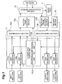
- Fig. 1 is a view illustrating a functional arrangement for a data transmission apparatus according to an embodiment of the invention.
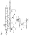
- Fig. 2 is an explanatory view illustrating a function of a multilink frame constituent section.
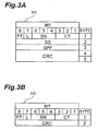
- Fig. 3A is a conceptual view illustrating a full header information.
- Fig. 3B is a conceptual view illustrating a compressed header information.
- Fig. 4 is explanatory view illustrating a multilink frame decoding section.
- Fig. 5 is an explanatory view illustrating a function of a deciding section.
- Fig. 6A shows an example of table values stored in a SS/SPF table.
- Fig. 6B shows an example of table values stored in the SS/SPF table.
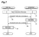
- Fig. 7 is a flow chart showing operations of a data transmission apparatus of the embodiment.
- Fig. 8 is a flow chart showing operations of the data transmission apparatus of the embodiment.
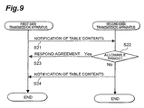
- Fig. 9 is a flow chart showing operations of the data transmission apparatus of the embodiment.
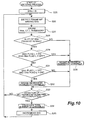
- Fig. 10 is a flow chart showing operations of the data transmission apparatus of the embodiment.
- Fig. 11 is a view illustrating a functional arrangement for data transmission in the related art.
- Fig. 1 is a view illustrating an exemplary functional arrangement of a data transmission apparatus 1 in the present embodiment.
- the data transmission apparatus 1 has a data input/output section 11, a multiplexing section 12A, a demultiplexing section 12B, a multilink frame constituent section13A, a multilink frame decoding section 13B, a deciding section 14, and a channel input/output section 15.
- An example of such a data transmission apparatus 1 is a multi-media communication terminal used in a television conference system or visual telephone system.
- the data transmission apparatus 1 in the present embodiment adopts Recommendation H.324 Annex H which has been standardized by ITU-T.
- the data input/output section 11 has a video encoding part 11Aa, a video decoding part 11Ab, an audio encoding part 11Ba, an audio decoding part 11Bb, and a communication control part 11C.
- the video encoding part 11Aa adopts ITU-T Recommendation H.263 or ISO/IEC MPEG (Moving Picture Experts Group)-4 as its video encoding method and encodes video data input to the data transmission apparatus 1 according to MPEG-4.
- the video decoding part 11Ab adopts ITU-T Recommendation H.263 or ISO/IEC MPEG-4 as its video decoding method and decodes video data output by the data transmission apparatus 1 according to MPEG-4.
- the audio encoding part 11Ba adopts ITU-T Recommendation G.723.1 or AMR (Adaptive Multi-Rate) method as its audio encodingmethod and encodes audio data input to the data transmission apparatus 1 according to the AMR method.
- the audio decoding part 11Bb adopts ITU-T Recommendation G.723.1 or the AMR method as its audio decoding method and decodes audio data output by the data transmission apparatus 1 according to the AMR method. Real-time video communication is made possible by simultaneously playing video data and audio data decoded in such a manner.
- the communication control part 11C has an H245 process part 11CA and an SRP process part 11CB.
- the H245 process part 11CA adopts ITU-T Recommendation H.245 and performs various processes related to multi-media communication with another data transmission apparatus 1 such as a channel assignment process and a message exchange process.
- the SRP process part 11CB adopts SRP (Simple Retransmission Protocol) which is a protocol for retransmission procedures defined in ITU-T Recommendation H.324 and performs a data retransmission process using the NSRP (Numbered SRP) or CCSRL (Control Channel Segmentation and Reassembly Layer) procedure when a transmission error occurs.
- SRP Simple Retransmission Protocol
- the multiplexing section 12A adopts ITU-T Recommendation H.223 (H.223 Annex A or H.223 Annex B may alternatively be adopted). It multiplexes video data and audio data encoded at the data input/output section 11 into one item of data to generate multiplex data and transmits the multiplex data thus generated to the multilink frame constituent section 13A.
- the demultiplexing section 12B adopts ITU-T Recommendation H.223 (H.223 Annex A or H.223 Annex B or may alternatively be adopted). It demultiplexes multiplex data combined at the multilink frame decoding section 13B into video data and audio data and transmits the demultiplexed video data and audio data to the data input/output section 11.
- the multilink frame constituent section 13A adopts ITU-T Recommendation H.324 Annex H and divides multiplex data which have been multiplexed at the multiplexing section 12A in accordance with the number of channels capable of communication on a multilink communication basis (a dividing process).
- the multilink frame decoding section 13B combines data received from another data transmission apparatus through a plurality of channels into one item of data to restore multiplex data (a combining process).
- the multilink frame constituent section 13A divides data D1 having been multiplexed at the multiplexing section 12A into units each having SS (Sampling Size) bytes.
- the multilink frame constituent section 13A sequentially distributes the data divided into units having SS (Sampling Size) bytes among a plurality of transmission channels CH1-CHn (n is a positive integer equal to or smaller than 8).
- the multilink frame constituent section 13A forms a set of data (hereinafter referred to as "payload PL") from the data (having SS bytes) in the quantity equal to SPF distributed to the transmission channel. Then, the multilink frame constituent section 13A provides a synchronization flag F and header information H associated with the payload PL to the same to generate one multilink frame MF. That is, the multilink frame MF includes the synchronization flag F, the header information H, and the payload PL having SS bytes x SPF (multiplication result of SS and SPF).
- the multilink frame constituent section 13A transmits the generated multilink frame MF to another data transmission apparatus through a transmission channel associated with the multilink frame MF.
- Such a dividing process makes it possible to transmit one item of multiplex data on a plurality of transmission channels on a divided basis.
- Figs. 3A and 3B show a conceptual view illustrating header information by way of example, and header information will be described with reference to the figures.
- Header information H includes full header information H1 and compressed header information H2. Stored in the first byte of the full header information H1 shown in Fig.
- CT Channel Tag
- SN Serial Number
- L Last
- FT Frame Type
- SS (the number of bytes) indicating the size of one item of divided data stored in the multilink frame MF is stored in the second byte of the full header information H1.
- SPF value indicative of the number indicating the number of items of divided data stored in the multilink frame MF is stored in the third byte of the full header information H1.
- a CRC Cyclic Redundancy Check
- CT, SN, L, and FT as described above are stored in the first byte of the compressed header information H2 shown in Fig. 3B , and CRC information is stored in the second byte of the same.
- CRC information is stored in the second byte of the same.
- SS and SPF included in the full header information H1 are not stored in the compressed header information H2.
- the header information H2 is used as the header information H. This makes it possible to reduce data to be transmitted.
- the combining process at the multilink frame decoding section 13B will now be described with reference to Fig. 4 .
- the multilink frames MF shown in Fig. 4 are indicated by numbers (SNs) representing the order in which the multilink frames MF have been transmitted, and numerals 0 to 7 are assigned to themas SNs.
- the flags L of the multilink frames MF transmitted on the transmission channel CH1 shown in Fig. 4 are in an OFF-state, and the flags L of the multilink frames MF transmitted on the transmission channel CH2 are in an ON-state.
- the flags L of the multilink frames MF transmitted on the transmission channel CH2 that is the channel having the greatest channel number (CT) are set in the ON-state.
- the multilink frame decoding section 13B of a data transmission apparatus 1 at a receiving end JG retrieves synchronization flags F from the multilink frames MF received from each of the transmission channels CH1 and CH2.
- the multilink frame decoding section 13B refers to numbers SN and flags L included in compressed header information H2 Following the detected synchronization flags F.
- the multilink frame decoding section 13B decides that multilink frames MF received from the transmission channels CH1 and CH2 respectively are multilink frames MF which have been transmitted from a data transmission apparatus 1 at a transmitting end SG at the same timing when those multilink frames MF have the same SN made clear as a result of the reference made to the numbers SN and flags L included in the compressed header information H2.
- a differential delay D2-D1 has occurred between the transmission channels CH1 and CH2 as shown in Fig. 4 .
- the multilink frame decoding section 13B of the data transmission apparatus 1 at the receiving end JG detects the synchronization flag F of the multilink frame MF whose SN is "0" on the channel CH1 when D1 [msec] has passed since the beginning of transmission and detects the synchronization flag F of the multilink frame MF whose SN is "0" on the channel CH2 when D2 [msec] has passed since the beginning of transmission. In this case, the multilink frame decoding section 13B decides that those multilink frames MF are multilink frames MF which have been transmitted at the same timing from the data transmission apparatus 1 at the transmitting end SG.
- the multilink frame decoding section 13B of the data transmission apparatus 1 at the receiving end JG decides that the transmission channel transmitting the multilink frames MF with flags L in the ON-state is the channel having the greatest channel number (CT) among the channels used as transmission channels for the multilink communication, i.e., the last transmission channel for the multilink communication.
- CT channel number
- the data received on the transmission channels CH1 and CH2 can be combined into one item of multiplex data by synchronizing the multilink frames MF transmitted on the transmission channels CH1 and CH2.
- the data received from the channels CH1 and CH2 can be combined into one item of multiplex data by alternately combining every SS bytes of the divided data included in the synchronized multilink frames MF from those channels in the order of the channel numbers (CT).
- CT channel numbers
- the deciding section 14 shown in Fig. 1 decides whether there has been any increase or decrease in the number of transmission channels used for multilink communication based on compressed header information H2 included in multilink frames MF received from another data transmission apparatus (a deciding process).
- a new transmission channel CH3 is added as an object of multilink communication when the multilink communication is performed using two transmission channels CH1 and CH2.
- the numbers (SNs) representing the order in which the multilink frames MF have been transmitted, and numerals 0 to 7 are assigned to them as SNs.
- the flags L of the multilink frames MF transmitted on the transmission channel CH1 are set in the OFF-state, and the flags L of the multilink frames MF transmitted on the transmission channel CH2 are set in the ON-state.
- the flags L on the transmission channel CH2 that is the channel having the greatest channel number (CT) are set in the ON-state.
- the flags L are flags indicating that the multilink frames MF are transmitted by the transmission channel having the greatest channel number (CT) from among transmission channels used for multilink communication.
- a transmission channel CH3 is newly added as a transmission channel for the multilink communication.
- the multilink section 13 of the data transmission apparatus at the transmitting end SG changes the state of the flags L of the multilink frames MF transmitted on the channel CH2 thereafter (starting with the frame having the SN "5") from ON to OFF and sets the flag L of multilink frames MF transmitted on the channel CH3 in the ON-state.
- CT channel number
- CT channel number
- the flags L of the multilink frames MF received from the transmission channel CH1 are set in the OFF-state, and the flags L of the multilink frames MF received from the transmission channel CH2 are set in the ON-state. Therefore, the multilink frame constituent section 13A of the data transmission apparatus at the receiving end JG synchronizes the multilink frames MF received from the transmission channels CH1 and CH2 respectively to combine the data received from the channels CH1 and CH2 into one item of multiplex data.
- the multilink frame decoding section 13B of the data transmission apparatus at the receiving end JG decides that the multilink frames MF received from the transmission channel CH2 are multilink frames MF which have been received from the last transmission channel for the multilink communication.
- the multilink frame decoding section 13B of the data transmission apparatus at the receiving end JG increments the SN value to identify the next multilink frames MF to be subjected to the synchronizing process.
- the multilink frame decoding section 13B of the data transmission apparatus at the receiving end JG synchronizes multilink frames MF having the SN "5" based on multilink frames MF received from the transmission channels CH1 and CH2 respectively.
- the multilink frame decoding section 13B of the data transmission apparatus at the receiving end JG detects that the flags L of the multilink frame MF received from the transmission channel CH2 has been changed from the ON-state to the OFF-state and recognizes that a multilink frame MF having the SN "5" is received also from the transmission channel CH3.
- the multilink frame decoding section 13B of the data transmission apparatus at the receiving end JG recognizes that the last transmission channel for the multilink communication has been changed from the transmission channel CH2 to the transmission channel CH3 by confirming that the flag L of the multilink frame MF (having the NS "5") received from the transmission channel CH3 is in the ON-state. That is, it recognizes that the number of transmission channels has increased from two to three.
- the decision on an increase in the number of channels is not limited to the same, and the decision may be made based on, for example, the channel number (CT) of a multilink frame MF received from a transmission channel. Specifically, when the channel number (CT) of the received multilink frame MF is different from the channel numbers (CT) of multilink frames MF which have been received, the addition of the new transmission channel may be recognized.
- CT channel number
- the channel input/output section 15 shown in Fig. 1 changes the size of the payload PL included in one multilink frame MF on referring to an SS/SPF table based on the number of transmission channels involved in multilink communication.
- the channel input/output section 15 changes the size of the payload PL when there is an increase or decrease in the number of transmission channels involved in multilink communication or when the increase or decrease in the number of transmission channels is confirmed.
- the timing of such a change is not limited to the time when the number of transmission channels is increased or decreased and the time when the increase or decrease in the number of transmission channels is confirmed.
- the size of the payload PL may be changed when several frames (a certain volume of transmission data) have been transmitted and received over each transmission channel after the occurrence of a change in the number of transmission channels or the confirmation of the change in the number of transmission channels.
- the size of the payload PL can be reliably changed even when a delay occurs between the transmission channels.
- an SS/SPF table T has a plurality of SS/SPF records R each of which is a set of a number of transmission channels, an SS value, and an SPF value associated with each other.
- each value stored in the table is set such that the size (data volume) of a payload PL calculated from a pattern expressed by "SSSPF" (a pattern of data division) increases as the number of transmission channels increases.
- SSSPF a pattern of data division
- patterns of SS and SPF values are set in the SS/SPF table T taking into account the fact that the likelihood of the occurrence of a delay between transmission channels increases with the number of transmission channels. Specifically, even when a delay occurs between transmission channels as a result of an increase in the number of transmission channels, it is possible to reduce situations in which synchronization between multilink frames MF fails by increasing the size of the payloads included in the multilink frames MF.
- each value stored in the table is set such that the size of a payload PL calculated from a pattern expressed by "SS SPF" (a pattern of data division) decreases as the number of transmission channels increases.
- SS and SPF values are set in the SS/SPF table T taking into account a case in which the capacity of a reception buffer at a receiving end is small and in which all transmission channels use the reception buffer in common. Specifically, even when a reception buffer capacity allocated to one channel decreases as a result of an increase in the number of transmission channels, it is possible to reduce situations in which a shortage of a reception buffer occurs by decreasing the size of payloads included in multilink frames MF.
- such an SS/SPF table T is generated by either of a data transmission apparatus at a transmitting end and a data transmission apparatus at a receiving end, based on the buffer capacity of the either data transmission apparatus.
- the apparatus then notifies the other apparatus of the contents of the table thus generated, and both of the apparatus thus have SS/SPF tables whose contents coincide with each other.
- a transmitter for data transmission may be arranged which has a video encoding section 11Aa, an audio encoding section 11Ba, a communication control section 11C, a multiplexing section 12A, a multilink frame constituent section 13A, a deciding section 14, and a channel input/output section 15.
- a receiver for data transmission may be arranged which has a video decoding section 11Ab, an audio decoding section 11Bb, a communication control section 11C, a demultiplexing section 12B, a multilink frame decoding section 13B, a deciding section 14, and a channel input/output section 15.
- Fig. 7 is a sequence chart showing operations during multilink communication for which no change is made in the number of transmission channels between the data transmission apparatus.
- Fig. 8 is a sequence chart showing operations that take place when the number of transmission channel is changed during multilink communication between the data transmission apparatus.
- the operations described are operations performed between the terminals when video data and audio data are transmitted and received between the data transmission apparatus using a plurality of channels allocated for multilink communication.
- a table determining process for determining the contents of an SS/SPF table T is performed between a first data transmission apparatus and a second data transmission apparatus (step S1). Details of the table determining process will be described later.
- the first data transmission apparatus generates multilink frames MF based on the SS/SPF table T decided by the table deciding process and transmits data including the multilink frames MF to the second data transmission apparatus through a plurality of transmission channels CH1-CHx (x is a positive integer).
- the first data transmission apparatus generatesthe multilink frames MF based on SS and SPF associated with the number of channels "x" and transmits the data to the second data transmission apparatus using "x" transmission channels.
- the second data transmission apparatus receives the data transmitted by the first data transmission apparatus and performs a deciding process for deciding whether there has been an'increase or decrease in the number of transmission channels based on channel numbers (CT) and flags L included in compressed header information H2 in the received multilink frames MF (step S3). Details of the deciding process will be described later.
- CT channel numbers
- the second data transmission apparatus When it is decided by the deciding process that the number of transmission channels has been neither increased nor decreased, the second data transmission apparatus generates multilink frames MF based on the SS/SPF table T and transmits data including the multilink frames MF to the first data transmission apparatus 1 through the plurality of transmission channels CH1-CHx (step S4).
- the first data transmission apparatus receives the data transmitted by the second data transmission apparatus and performs a deciding process for deciding whether there has been an increase or decrease in the number of transmission channels based on channel numbers (CT) and flags L included in compressed header information H2 in the received multilink frames MF (step S5).
- CT channel numbers
- L included in compressed header information H2 in the received multilink frames MF
- the multilink communication using "x" transmission channels is continued between the first data transmission apparatus and the second data transmission apparatus.
- the first data transmission apparatus changes the number of transmission channels involved in multilink communication from "x" to "y” (step S11).
- the first data transmission apparatus acquires a pattern of SS and SPF associated with the number of transmission channels "y” from the SS/SPF table T (step S12).
- it generates multilink frames MF based on the acquired SS and SPF and transmits data including the multilink frames MF to the second data transmission apparatus through the transmission channels CH1-CHy thus changed (step S13). That is, the first data transmission apparatus transmits the data to the second data transmission apparatus using "y" transmission channels.
- the second data transmission apparatus receives the data transmitted by the first data transmission apparatus and performs a deciding process for deciding whether there has been an increase or decrease in the number of transmission channels based on channel numbers (CT) and flags L included in compressed header information H2 in the received multilink frames MF (step S14). Details of the deciding process will be described later.
- CT channel numbers
- the second data transmission apparatus acquires the pattern of SS and SPF associated with the number of transmission channels "y" from the SS/SPF table T (step S15). Then, the second data transmission apparatus generates multilink frames MF based on the acquired SS and SPF and transmits data including the multilink frames MF to the first data transmission apparatus through the plurality of transmission channels CH1-CHy (step S16).
- the first data transmission apparatus notifies the second data transmission apparatus of contents of an SS/SPF table T which have been generated taking into account the buffer capacity and terminal capabilities of the first apparatus itself during reception and transmission (step S21).
- the second data transmission apparatus decides whether the contents of the SS/SPF table T received from the first data transmission apparatus are in an allowable range with respect to the buffer capacity and terminal capability of the second apparatus itself during reception and transmission (step S22). If the decision is YES (step S22; YES), the second data transmission apparatus makes a response indicating that it agrees to the contents of the SS/SPF table T received from the first data transmission apparatus (step S23).
- step S22 If it is decided at step S22 that the contents are out of the allowable range (step S22; NO), the second data transmission apparatus notifies the first data transmission apparatus of contents of the SS/SPF table T which have been generated taking into account the buffer capacity and terminal capabilities of the second apparatus itself during reception and transmission (step S24).
- a response may be made which indicates that full header information H1 including SS and SPF is to be used as header information H.
- full header information H1 including SS and SPF is to be used as header information H.
- multilink communication using full header information H1 may be performed as done in the related art.
- a data transmission apparatus sets SNs that are numbers indicating the order of transmission of multilink frames MF, to an initial value "0" (step S25).
- the SNs in the present embodiment are represented by natural numbers from 0 to 7.
- the numbers "0" to “7” are sequentially assigned to the SNs as the order in which multilink framesMFhave been transmi tted, and "7" is followed by "0" from which the numbers are similarly assigned again.
- the SN of a multilink frame which is to be currently subjected to the combining process is represented by SNn
- the SN indicating the place preceding the SNn in the order of transmission is represented by SNm.
- the data transmission apparatus detects the multilink frame MF numbered SNn from data stored in the reception buffer thereof (step S26).
- the data transmission apparatus then stores the channel number (CT) and the flag L included in the detected multilink frame MF in a memory in accordance with the number SNn (step S27).
- the data transmission apparatus decides whether the channel number CT associated with the number SNn is present among the channel numbers CT associated with the number SNm (step S28). That is, the data transmission apparatus decides whether the channel number CT associated with the number SNn is a newly detected channel number (CT) .
- the decision is not made at the time of an initial process (a process that is performed when "0" is initially stored as the number SNn at step S25). This is because the number SNm does not exist at the time of the initial process. Process at steps S29 to S32 to be described below are not also performed at the time of the initial process for the same reason.
- step S28 If the result of the decision at step S28 is NO (step S28; NO), the process proceeds to step S30. If it is decided at step S28 that the channel number CT associated with the number SNn is present among the channel numbers CT associated with the number SNm (step S28; YES), the data transmission apparatus decides whether the flag L associated with the number SNm is in the ON-state and the flag L associated with the number SNn is in the OFF-state (step S29). That is, the data transmission apparatus decides whether the flag L has changed from the ON-state to the OFF-state for the same channel number (CT). If the result of the decision is YES (step S29; YES) , the data transmission apparatus decides that the number of transmission channels has been increased (step S30), and the process proceeds to step S33.
- step S29; NO the data transmission apparatus decides whether the flag L associated with the number SNm is in the OFF-state and the flag L associated with the number SNn is in the ON-state (step S31). That is, the data transmission apparatus decides whether the flag L has changed from the OFF-state to the ON-state for the same channel number (CT). If the result of the decision is YES (step S31; YES), the data transmission apparatus decides that the number of transmission channels has been decreased (step S32). If the result of the decision at step S31 is NO (step S31; NO), the process proceeds to step S33.
- the data transmission apparatus decides whether detection of all multilink frames MF having the number SNn has been completed or not (step S33). Specifically, the detection may be decided, for example, by checking whether a multilink frame MF associated with the number SNn and having a flag L in the ON-state has already been detected and by checking whether all multilink frames MF having channel numbers (CT) equal to or smaller than the channel number (CT) associated with that multilink frame MF have been detected. This is because the channel number (CT) of the multilink frame MF having the flag L in the ON-state is the greatest channel number (CT) for the frames with the number SNn.
- CT channel numbers
- step S33 the data transmission apparatus proceeds to the process at step S26. If it is decided at step S33 that the detection of all multilink frames MF having the number SNn has been completed (step S33; YES), the data transmission apparatus calculates the number of channels currently involved in multilink communication (step S34). Referring to the calculation specifically, for example, the total number of channel numbers CT associated with the number SNn stored in the memory may be calculated as the number of channels.
- step S35 the data transmission apparatus increments the number SNn, and the process then proceeds to step S26 (step S35).
- the size (data volume) of a payload PL included in a multilink frame MF and a pattern of SS and SPF (a pattern of data division) can be controlled based on the number of transmission channels involved in multilink communication as described above. Therefore in the case of a change in the number of transmission channels, the size of the payload PL or the pattern of SS and SPF can be controlled based on the number of transmission channels after that change. That is, data are transmitted using multilink frames MF generated based on a payload PL or a pattern of SS and SPF which is suitable for the number of transmission channels after the change, and the transmission efficiency of the transmission channels during multilink communication can be improved.
- a multilink frame MF may have only compressed header information H2 as header information. This eliminates a need for using full header information as the header information of the multilink frame, and the transmission efficiency of the channel can therefore be improved during mul tilink communication. Further, since SS and SPF values can be easily changed by acquiring a pattern of SS and SPF in accordance with a change in the number of transmission channels from the SS/SPF table, the load of processing can be reduced.
- a data receiving end checks whether the size of a payload has been changed or not with reference to header information of all multilink frames received. According to the invention, since only compressed header information is used as header information of multilink frames, there is no need for referring to header information of all multilink frames to check whether the payload size has been changed. Therefore, the load of processing can be reduced accordingly.
- the data transmission method and data transmission apparatus of the invention make it possible to improve the transmission efficiency of channels involved in multilink communication and to reduce the load of processing.
Landscapes
- Engineering & Computer Science (AREA)
- Power Engineering (AREA)
- Computer Networks & Wireless Communication (AREA)
- Signal Processing (AREA)
- Time-Division Multiplex Systems (AREA)
- Communication Control (AREA)
Claims (2)
- Procédé de transmission de données comprenant les étapes consistant à :diviser les données à transmettre en une pluralité d'unités de données, chacune d'elles présentant un même nombre d'octets de taille d'échantillonnage, SS, et distribuer les unités de données qui présentent le même nombre d'octets SS parmi une pluralité de canaux de transmission (CH1, CH2, ... , CHn), et, quand une quantité d'unités de données distribuées au canal de transmission atteint un certain nombre d'échantillons par trame, SPF, transmettre les unités de données qui présentent la quantité ayant le nombre SPF, à l'aide d'un terminal de transmission ; etrecevoir les données distribuées parmi, et transmises sur, la pluralité de canaux de transmission et combiner les données reçues à l'aide d'un terminal de réception ;le procédé de transmission de données étant caractérisé en ce que le procédé de transmission de données comprend en outre :une étape, exécutée par le terminal de transmission, consistant à générer une table qui fixe le SS et le SPF, sur la base d'un certain nombre de canaux de transmission ;une étape (S21), exécutée par le terminal de transmission, consistant à notifier au terminal de réception le contenu de la table ;une étape (S22), exécutée par le terminal de réception, consistant à décider si le contenu de la table se situe dans une plage autorisée en ce qui concerne la capacité d'un tampon et les capacités de terminal du terminal de réception, et à transmettre la décision au terminal de transmission lorsque le terminal de réception décide que le contenu de la table se situe dans une plage autorisée ; etune étape, exécutée par le terminal de transmission, consistant à contrôler la longueur et la quantité d'unités de données selon le contenu de la table lorsque le terminal de transmission reçoit la décision que le contenu de la table se situe dans une plage autorisée ; etdans l'étape consistant à générer la table :normalement, le terminal de transmission génère la table qui fixe le SS et le SPF de telle sorte qu'une taille de données utiles calculée en multipliant le SS par le SPF, augmente à mesure que le nombre de canaux de transmission augmente ; etlorsque la capacité d'un tampon de réception au niveau d'un terminal de réception est petite, le terminal de transmission génère la table qui fixe le SS et le SPF de telle sorte qu'une taille de données utiles calculée en multipliant le SS par le SPF, diminue à mesure que le nombre de canaux de transmission augmente.
- Appareil de transmission de données (1), comprenant :une unité de division (12A) destinée à diviser des données à transmettre en une pluralité d'unités de données qui présentent un même nombre d'octets SS ;une unité de transmission (13A) destinée à distribuer les unités de données, chacune d'elles présentant le même nombre d'octets SS parmi une pluralité de canaux de transmission, et à transmettre, quand une quantité d'unités de données distribuées au canal de transmission atteint un certain nombre SPF, les unités de données à un terminal de réception ;l'appareil de transmission de données (1) étant caractérisé en ce que l'appareil de transmission de données comprend en outre :une unité de génération destinée à générer une table qui fixe le SS et le SPF selon un certain nombre de canaux de ladite pluralité de canaux de transmission, sur la base d'une capacité de tampon et de capacités de terminal de l'appareil de transmission de données ;une unité de notification (15) destinée à notifier au terminal de réception le contenu de la table ; etune unité de commande (14) destinée à commander SS et SPF selon le contenu de la table lors de la réception d'une réponse selon laquelle le contenu de la table se situe dans une plage autorisée ; etdans lequel l'unité de génération :est adaptée, normalement, de façon à générer la table qui fixe le SS et le SPF, de telle sorte qu'une taille de données utiles calculée en multipliant le SS par le SPF augmente à mesure que le nombre de canaux de transmission augmente ; etlorsque la capacité d'un tampon de réception au niveau d'un terminal de réception est petite, est adaptée de façon à générer la table qui fixe le SS et le SPF de telle sorte qu'une taille de données utiles calculée en multipliant le SS par le SPF diminue à mesure que le nombre de canaux de transmission augmente.
Applications Claiming Priority (2)
| Application Number | Priority Date | Filing Date | Title |
|---|---|---|---|
| JP2002367287A JP4199997B2 (ja) | 2002-12-18 | 2002-12-18 | データ伝送方法、データ伝送装置およびデータ伝送システム |
| JP2002367287 | 2002-12-18 |
Publications (2)
| Publication Number | Publication Date |
|---|---|
| EP1432191A1 EP1432191A1 (fr) | 2004-06-23 |
| EP1432191B1 true EP1432191B1 (fr) | 2012-02-22 |
Family
ID=32376280
Family Applications (1)
| Application Number | Title | Priority Date | Filing Date |
|---|---|---|---|
| EP20030028967 Expired - Lifetime EP1432191B1 (fr) | 2002-12-18 | 2003-12-17 | Procédé et appareil de transmission de données en utilisant un protocole de liaisons multiples |
Country Status (4)
| Country | Link |
|---|---|
| US (1) | US7630413B2 (fr) |
| EP (1) | EP1432191B1 (fr) |
| JP (1) | JP4199997B2 (fr) |
| CN (1) | CN1514620A (fr) |
Families Citing this family (12)
| Publication number | Priority date | Publication date | Assignee | Title |
|---|---|---|---|---|
| GB0421664D0 (en) * | 2004-09-29 | 2004-10-27 | Nokia Corp | Method for commuication over a lossy interface |
| US7965736B2 (en) | 2005-08-24 | 2011-06-21 | Qualcomm Incorporated | Transmission of multiplex protocol data units in physical layer packets |
| US8611258B1 (en) * | 2005-09-30 | 2013-12-17 | At&T Intellectual Property Ii, L.P. | Method and apparatus for integrating video and instant messaging application sessions |
| US20080288958A1 (en) * | 2005-11-07 | 2008-11-20 | Seung Hyup Ryoo | Near Field Communication Host Controller Interface |
| CN101039310B (zh) * | 2006-03-16 | 2010-08-25 | 联想(北京)有限公司 | 链路共享服务装置以及通信方法 |
| CN101039309B (zh) * | 2006-03-16 | 2010-09-29 | 联想(北京)有限公司 | 链路共享服务装置以及通信方法 |
| US8713393B2 (en) * | 2007-10-02 | 2014-04-29 | Lantiq Deutschland Gmbh | Retransmission and retransmission request in data communication systems |
| JP4623196B2 (ja) * | 2008-10-08 | 2011-02-02 | 富士ゼロックス株式会社 | 画像処理装置、画像処理システム、及びプログラム |
| CN101720107B (zh) * | 2009-03-23 | 2013-05-29 | 上海通琅信息技术有限公司 | 无线多媒体传输的多路联合通信系统及方法 |
| JP2012070198A (ja) * | 2010-09-23 | 2012-04-05 | Nec Engineering Ltd | 映像伝送システム |
| JP5772132B2 (ja) * | 2011-03-25 | 2015-09-02 | 富士通株式会社 | データ転送装置、データ転送方法および情報処理装置 |
| CN107018399A (zh) * | 2017-03-28 | 2017-08-04 | 北京犀牛数字互动科技有限公司 | 图像数据传输方法及装置 |
Family Cites Families (13)
| Publication number | Priority date | Publication date | Assignee | Title |
|---|---|---|---|---|
| US5231649A (en) | 1991-08-08 | 1993-07-27 | Ascend Communications, Inc. | Method and apparatus for dynamic bandwidth allocation in a digital communication session |
| JPH05153183A (ja) | 1991-11-27 | 1993-06-18 | Hitachi Ltd | 複数のリンクを用いたデータ転送方式 |
| US6240140B1 (en) * | 1997-02-24 | 2001-05-29 | Picturetel Corporation | Channel aggregation having low latency and overhead |
| US6411629B1 (en) * | 1998-12-29 | 2002-06-25 | Northern Telecom Limited | Data interleaving method |
| US6335933B1 (en) * | 1999-05-21 | 2002-01-01 | Broadcom Homenetworking, Inc. | Limited automatic repeat request protocol for frame-based communication channels |
| US6999429B1 (en) * | 2000-03-03 | 2006-02-14 | Telefonaktiebolaget Lm Ericsson | Access technology integrated header compression |
| EP1148687A1 (fr) * | 2000-04-20 | 2001-10-24 | Telefonaktiebolaget L M Ericsson (Publ) | Dispositif pour communication |
| FR2809577B1 (fr) * | 2000-05-25 | 2002-10-18 | Mitsubishi Electric Inf Tech | Methode de transmission de donnees combattant la degradation de la qualite de service |
| US7082569B2 (en) * | 2001-01-17 | 2006-07-25 | Outlooksoft Corporation | Systems and methods providing dynamic spreadsheet functionality |
| US7054291B2 (en) * | 2001-01-22 | 2006-05-30 | Telefonaktiebolaget Lm Ericsson (Publ) | Method of and system for mobile station abbreviated point-to-point protocol negotiation |
| US6490296B2 (en) * | 2001-02-28 | 2002-12-03 | Symmetricom, Inc. | Multi-link segmentation and reassembly for bonding multiple PVC's in an inverse multiplexing arrangement |
| US6879590B2 (en) * | 2002-04-26 | 2005-04-12 | Valo, Inc. | Methods, apparatuses and systems facilitating aggregation of physical links into logical link |
| US7277419B2 (en) * | 2002-08-30 | 2007-10-02 | Intel Corporation | Supporting disparate packet based wireless communications |
-
2002
- 2002-12-18 JP JP2002367287A patent/JP4199997B2/ja not_active Expired - Fee Related
-
2003
- 2003-12-17 EP EP20030028967 patent/EP1432191B1/fr not_active Expired - Lifetime
- 2003-12-18 CN CNA2003101223121A patent/CN1514620A/zh active Pending
- 2003-12-18 US US10/737,763 patent/US7630413B2/en not_active Expired - Fee Related
Also Published As
| Publication number | Publication date |
|---|---|
| JP4199997B2 (ja) | 2008-12-24 |
| US20040179556A1 (en) | 2004-09-16 |
| JP2004201037A (ja) | 2004-07-15 |
| EP1432191A1 (fr) | 2004-06-23 |
| CN1514620A (zh) | 2004-07-21 |
| US7630413B2 (en) | 2009-12-08 |
Similar Documents
| Publication | Publication Date | Title |
|---|---|---|
| EP0446956B1 (fr) | Système de transmission de données à vitesse de transmission variable | |
| EP0753235B1 (fr) | Gestion de tampons destinee a des systemes de compression a debit binaire variable | |
| EP1432191B1 (fr) | Procédé et appareil de transmission de données en utilisant un protocole de liaisons multiples | |
| CN1682474B (zh) | 用于网络信号整合和带宽缩减的方法和装置 | |
| AU733331B2 (en) | Method and apparatus for processing data from multiple sources | |
| EP0618730B1 (fr) | Traitement de signaux vidéo codés selon leur priorité | |
| KR100382711B1 (ko) | 고품질로 신을 표시할 수 있는 송신 시스템, 수신 시스템,및 송수신 시스템 | |
| US5751694A (en) | Methods and apparatus for synchronizing temporally related data streams | |
| KR19980069768A (ko) | 다중전송방법 및 시스템과 거기에서 사용되는 음성파동 흡수방법 | |
| JP2002536889A (ja) | 統計的マルチプレクサのバンド幅を十分にすることを確実にする方法および装置 | |
| EP0637892B1 (fr) | Système et méthode pour la transmission d'images à haute efficacité | |
| JP2002535934A (ja) | リファレンス信号情報を規定時間間隔で配信する方法および装置 | |
| JP3930802B2 (ja) | データ伝送方法、データ伝送装置およびデータ伝送システム | |
| EP1393525B1 (fr) | Procede de transmission de flux d'information, systeme de transmission correspondant, recepteur et produit informatique | |
| US10264251B2 (en) | Encoding/transmitting apparatus and encoding/transmitting method | |
| US7400592B1 (en) | Picture distribution system and method thereof | |
| JP2002152181A (ja) | マルチメディアデータ通信方法およびマルチメディアデータ通信装置 | |
| WO1997038532A1 (fr) | Commande de tampon dans un systeme de transmission de donnees codees | |
| JPH11196130A (ja) | パケット伝送システムおよびパケット伝送方法 | |
| JP3730332B2 (ja) | マルチメディア多重化通信システム | |
| KR100763013B1 (ko) | 복수의 소스들로부터 데이터를 처리하기 위한 방법 및 장치 | |
| US20060153249A1 (en) | Multiplexing device and data processing method thereof | |
| JPH02246432A (ja) | 映像・音声多重化方式 | |
| EP1946498B1 (fr) | Systeme et procede de communication | |
| GB2432277A (en) | Asynchronous transfer mode (ATM) cells containing switch commands |
Legal Events
| Date | Code | Title | Description |
|---|---|---|---|
| PUAI | Public reference made under article 153(3) epc to a published international application that has entered the european phase |
Free format text: ORIGINAL CODE: 0009012 |
|
| 17P | Request for examination filed |
Effective date: 20031217 |
|
| AK | Designated contracting states |
Kind code of ref document: A1 Designated state(s): AT BE BG CH CY CZ DE DK EE ES FI FR GB GR HU IE IT LI LU MC NL PT RO SE SI SK TR |
|
| AX | Request for extension of the european patent |
Extension state: AL LT LV MK |
|
| 17Q | First examination report despatched |
Effective date: 20040726 |
|
| AKX | Designation fees paid |
Designated state(s): DE GB |
|
| 17Q | First examination report despatched |
Effective date: 20040726 |
|
| GRAP | Despatch of communication of intention to grant a patent |
Free format text: ORIGINAL CODE: EPIDOSNIGR1 |
|
| RIN1 | Information on inventor provided before grant (corrected) |
Inventor name: ADACHI, SATORU,C/O INTELLECTUAL PROPERTY DEPARTAME Inventor name: KATO, SADAATSU,C/O INTELLECTUAL PROPERTY DEPARTAME Inventor name: SUGIMOTO, KAZUO,C/O INTELLECTUAL PROPERTY DEPARTAM Inventor name: KOBAYASHI, MITSURUC/O INTELLECTUAL PROPERTY DEPART Inventor name: YAMAGUCHI, HIROYUKI, C/O INTELLECTUAL PROPERTY DEP |
|
| GRAS | Grant fee paid |
Free format text: ORIGINAL CODE: EPIDOSNIGR3 |
|
| RIN1 | Information on inventor provided before grant (corrected) |
Inventor name: KATO, SADAATSU,C/O INTELLECTUAL PROPERTY DEPARTMEN Inventor name: YAMAGUCHI, HIROYUKI, C/O INTELLECTUAL PROPERTY DEP Inventor name: KOBAYASHI, MITSURUC/O INTELLECTUAL PROPERTY DEPART Inventor name: ADACHI, SATORU,C/O INTELLECTUAL PROPERTY DEPARTMEN Inventor name: SUGIMOTO, KAZUO,C/O INTELLECTUAL PROPERTY DEPARTME |
|
| GRAA | (expected) grant |
Free format text: ORIGINAL CODE: 0009210 |
|
| AK | Designated contracting states |
Kind code of ref document: B1 Designated state(s): DE GB |
|
| REG | Reference to a national code |
Ref country code: GB Ref legal event code: FG4D |
|
| REG | Reference to a national code |
Ref country code: DE Ref legal event code: R096 Ref document number: 60340046 Country of ref document: DE Effective date: 20120419 |
|
| PLBE | No opposition filed within time limit |
Free format text: ORIGINAL CODE: 0009261 |
|
| STAA | Information on the status of an ep patent application or granted ep patent |
Free format text: STATUS: NO OPPOSITION FILED WITHIN TIME LIMIT |
|
| 26N | No opposition filed |
Effective date: 20121123 |
|
| REG | Reference to a national code |
Ref country code: DE Ref legal event code: R097 Ref document number: 60340046 Country of ref document: DE Effective date: 20121123 |
|
| PGFP | Annual fee paid to national office [announced via postgrant information from national office to epo] |
Ref country code: GB Payment date: 20131211 Year of fee payment: 11 Ref country code: DE Payment date: 20131211 Year of fee payment: 11 |
|
| REG | Reference to a national code |
Ref country code: DE Ref legal event code: R119 Ref document number: 60340046 Country of ref document: DE |
|
| GBPC | Gb: european patent ceased through non-payment of renewal fee |
Effective date: 20141217 |
|
| PG25 | Lapsed in a contracting state [announced via postgrant information from national office to epo] |
Ref country code: GB Free format text: LAPSE BECAUSE OF NON-PAYMENT OF DUE FEES Effective date: 20141217 Ref country code: DE Free format text: LAPSE BECAUSE OF NON-PAYMENT OF DUE FEES Effective date: 20150701 |