EP1432235A2 - Verfahren und Anordnung zur Wiedergabe eines Bildsignals - Google Patents
Verfahren und Anordnung zur Wiedergabe eines Bildsignals Download PDFInfo
- Publication number
- EP1432235A2 EP1432235A2 EP03253167A EP03253167A EP1432235A2 EP 1432235 A2 EP1432235 A2 EP 1432235A2 EP 03253167 A EP03253167 A EP 03253167A EP 03253167 A EP03253167 A EP 03253167A EP 1432235 A2 EP1432235 A2 EP 1432235A2
- Authority
- EP
- European Patent Office
- Prior art keywords
- pixel
- value
- mask
- mask cell
- sub
- Prior art date
- Legal status (The legal status is an assumption and is not a legal conclusion. Google has not performed a legal analysis and makes no representation as to the accuracy of the status listed.)
- Withdrawn
Links
Images




Classifications
-
- H—ELECTRICITY
- H04—ELECTRIC COMMUNICATION TECHNIQUE
- H04N—PICTORIAL COMMUNICATION, e.g. TELEVISION
- H04N9/00—Details of colour television systems
- H04N9/64—Circuits for processing colour signals
- H04N9/67—Circuits for processing colour signals for matrixing
Definitions
- the present invention relates to a method and apparatus for rendering an image signal using a multicolored image signal rendering apparatus, and more particularly, a method and apparatus for rendering an image signal by adding a fourth color component, to an image signal composed of three colors (for example, RGB).
- a pixel is composed of sub-pixels having three different colors, for example, red (R), green (G), and blue (B).
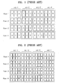
- FIG. 1 shows an example of a filter arrangement of an RGB-striped structure.
- FIG. 2 shows an example of an RGBW filter structure of a conventional RGBW type apparatus for rendering an image signal in which luminance is improved by adding a fourth color sub-pixel (for example, white) to sub-pixels representing RGB colors.
- a fourth color sub-pixel for example, white
- FIG. 2 shows an example of an RGBW filter structure of a conventional RGBW type apparatus for rendering an image signal in which luminance is improved by adding a fourth color sub-pixel (for example, white) to sub-pixels representing RGB colors.
- the output light of the pixel can be increased.
- the sizes of RGB filters become smaller compared to a pixel in which only three RGB colors are used as shown in FIG. 1.
- the output light of RGB primary colors becomes rather reduced compared to the pixel in which only three RGB sub-pixels are used.
- driver integrated circuits (ICs) for driving the white filter are needed, manufacturing costs of these filters increase.
- FIG. 3 shows another example of an RGBW filter structure of a conventional RGBW type apparatus for rendering an image signal in which luminance is improved by adding a fourth color sub-pixel (for example, white) to sub-pixels of RGB colors.
- a fourth color sub-pixel for example, white
- pixel is composed of 2 x 2 sub-pixels, the same problems as in the RGBW filters shown in FIG. 2 occur.
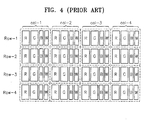
- FIG. 4 shows still another example of an RGBW filter structure of a conventional RGBW type apparatus for rendering an image signal in which luminance is improved by adding a fourth color sub-pixel (for example, white) to sub-pixels of RGB colors.
- a fourth color sub-pixel for example, white
- the sizes of blue and white filters are small and the sizes of red and green filters are the same as the sizes of sub-pixels of R and G colors at a pixel in which only three RGB colors are used.
- an output light increase caused by the white filter an output light decrease of primary colors such as red and green can be prevented.
- the driver ICs for driving the white filter are additionally required, the manufacturing costs in this case increase as well.
- a method for rendering image signals which represent a predetermined number of colors in an apparatus for rendering an image signal of which pixels have three sub-pixels comprises (a) receiving a predetermined number of color signals and converting the predetermined number of color signals into four-color signals to be represented in the sub-pixels, (b) selecting two-color signals to be outputted alternatively in every other pixels out of the four-color signals and selecting only one-color signal for each position of a pixel area from the two-color signal, (c) recalculating a level value of the selected one-color signal to be represented in the sub-pixels, and (d) controlling image signals to be represented in the sub-pixels according to the level value of the one-color signal calculated in (c).
- the present invention provides a method and apparatus for rendering an image signal in which an output light decrease of primary colors such as red (R), green (G), and blue (B) is minimized, additional driver integrated circuits (ICs) for driving a fourth color filter are not needed, and an original image signal composed of three RGB primary colors is rendered as a signal composed of four primary colors.
- primary colors such as red (R), green (G), and blue (B)
- the level value of the one-color signal selected in (b) is calculated according to peripheral sub-pixel values using a mask having a size corresponding to the size of each pixel of the apparatus for rendering an image signal and composed of a predetermined number of cells.
- (c) comprises (c1) calculating a difference value for each mask cell, (c2) calculating an increase/decrease amount of a pixel value using a pixel value and a difference value for each mask cell, and (c3) calculating a pixel value of an entire mask cell using the pixel value for each mask and the increase/decrease amount of the pixel value for each mask cell.
- an apparatus for rendering an image signal of which pixels have three sub-pixels includes a signal conversion unit to receive a predetermined number of color signals and convert the predetermined number of color signals into four-color signals, a signal selection unit to select two-color signals to be outputted alternatively in every other pixels out of the four-color signals and select only one-color signal for each position of a pixel area from the two-color signal, a level value recalculation unit to recalculate a level value of the selected one-color signal to be represented in the sub-pixels, and a display driver to control image signals to be represented in the sub-pixels according to sub-pixel values received from the level value recalculation unit.
- the level value recalculation unit includes a difference value calculation part to calculate a difference value for each mask cell, an increase/decrease calculation part to calculate an increase/decrease amount of a pixel value using the pixel value and the difference value for each mask cell, and a sub-pixel value calculation part to calculate a sub-pixel value of an entire mask cell using the pixel value for each mask cell and the increase/decrease amount of the pixel value for each mask cell.
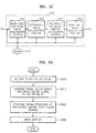
- FIG. 5A is a block diagram illustrating the structure of an apparatus for rendering an image signal according to a preferred embodiment of the present invention
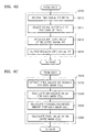
- FIG. 6A is a flowchart illustrating a method for rendering an image signal performed in the apparatus for rendering an image signal according to a preferred embodiment of the present invention.
- the apparatus for rendering an image signal includes a signal conversion unit 510, a signal rendering unit 520, and a display driver 530.
- the signal conversion unit 510 receives three primary color image data Ri, Gi, and Bi to be displayed (S600) and generates four primary color signals P1, P2, P3, and P4.
- P1, P2, and P3 may respectively be R, G, and B colors
- the fourth primary color signal P4 is different from the P1, P2, and P3 color signals, and may be, for example, white, yellow, or cyan.
- an RGBW four channel signal is generated by extracting a W signal from sub-pixels of RGB colors and updating a corresponding RGB signal using the extracted W signal.
- the signal conversion unit 510 converts a three-color (for example, RGB) signal into a four-color (for example, RGBW) signal using a variety of existing signal converting methods (S610).
- the signal rendering unit 520 receives P3 and P4 signals among the four-channel signals P1, P2, P3, and P4 from the signal conversion unit 510, and simultaneously, receives a signal Cont_1 511 which indicates an image coordinate of a corresponding signal, and a data signal DataS 512 which indicates a level value of a corresponding channel in the vicinity of a corresponding coordinate, calculates a level value of a sub-pixel to be rendered in an apparatus for rendering an image signal, and outputs the calculated level value to the display driver 530 (S620).
- an outputted signal P5 is a level value obtained by recalculating the signals P3 or P4.
- the display driver 530 receives the signals P1 and P2 generated in the signal conversion unit 510 and the signal P5 generated in the signal rendering unit 520 and controls an image signal to be rendered on a display (S680).
- step S620 will be described in detail further with reference to FIGS. 7 through 10 illustrating the structure of four-color filters C1, C2, C3, and C4, according to a preferred embodiment of the present invention.
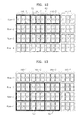
- Each pixel shown in FIG. 7 has a total of three sub-pixels, like a pixel of a conventional apparatus for rendering an image signal shown in FIG. 1, and sub-pixels C3 and C4 exist in every other pixels.
- the filters comprising C1, C2, C3, and C4 as a sub-pixel shown in FIG. 7 a sub-pixel arrangement is made such that, in all rows, a pixel composed of the filters C1, C2, and C3 and a pixel composed of the filters C1, C2, and C4 are arranged alternately, and in each column, a pixel is composed of the same filters C1, C2, and C3 or a pixel is composed of the same filters C1, C2, and C4.
- a sub-pixel arrangement is made such that, in all rows, the pixel composed of the filters C1, C2, and C3, and the pixel composed of the filters C1, C2, and C4 are arranged alternately, and even in all columns, the pixel composed of the filters C1, C2, and C3, and the pixel composed of the filters C1, C2, and C4 are arranged alternately.
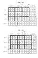
- a pixel composed of the filters C1, C3, and C2 and a pixel composed of the filters C1, C4, and C2 are arranged alternately, and in an even row, a pixel composed of the filters C2, C4, and C1 and a pixel composed of the filters C2, C3, and C1 are arranged alternately, and in each column, a sub-pixel filters C3 and C4 is arranged alternately.
- an odd row has a pixel composed of the filters C1, C3, and C2, and an even row has a pixel composed of the filters C2, C4, and C1.
- a pixel in each column has a sub-pixel filters C3 and C4 alternatively.
- FIGS. 7 through 10 show examples of the structures of the filters C1, C2, and C3-C1, C2, and C4 of C1, C2, C3, and C4 type apparatus for rendering an image signal in which a fourth sub-pixel is added to the filters C1, C2, and C3.
- a method by which a correct image is rendered by color matching performed according to positions of sub-pixels for example, sub-pixels C3 and C4 having a relatively low spatial resolution is required.
- a level value of a signal to be rendered at sub-pixels C3 and C4 is recalculated using values of the sub-pixels C3 and C4 to be rendered at a peripheral pixel, thereby preventing a color distortion.
- the structure of the signal rendering unit 520 for rendering a signal and the step of recalculating signal values of sub-pixels C3 and C4 will be described with reference to FIGS. 5B, 5C, 6B, and FIGS. 6C through 6F.
- FIG. 5B is a block diagram illustrating the structure of the signal rendering unit 520 shown in FIG. 5A.
- the signal rendering unit 520 shown in FIG. 5B includes a signal selection part 515 and a level value recalculation part 516.
- FIG. 6B is a detailed flowchart illustrating the step of rendering signals of sub-pixels C3 and C4 performed by the signal rendering unit 520. Referring to FIGS.
- the signal selection part 515 receives the signals P3 and P4 among the four-color signals output from the signal conversion unit 510 (S612), and, simultaneously receives the signal Cont_1 511 which indicates an image coordinate of a corresponding signal, selects the type of a sub-pixel to be rendered at a corresponding position (for example, in the case of a sub-pixel comprising the filter C3, the signal P3) (S614), and outputs a corresponding signal P6 to the level value recalculation part 516.
- the level value recalculation unit 516 receives the selected signal P6, and simultaneously receives the data signal DataS 512 which indicates level values of a corresponding channel in the vicinity of a coordinate of a corresponding signal, calculates level values of sub-pixels to be rendered in an apparatus for rendering an image signal (S616), and outputs the signal P5 which is the result of calculation, to the display driver 530 (S618).
- FIG. 5C is a block diagram illustrating the structure of the level value recalculation part 516 shown in FIG. 5B.
- the level value recalculation part 516 shown in FIG. 5C includes a mask-cell sub-pixel value assignment portion 521, a difference value calculation portion 522, an increase/decrease amount calculation portion 524, and a sub-pixel value calculation portion 526.
- FIG. 6C is a flowchart illustrating the step of recalculating signal values of sub-pixels C3 and C4, performed by the level value recalculation part 516.
- the mask-cell sub-pixel value assignment portion 521 receives the signal P6 inputted from the signal selection part 515, and simultaneously receives sub-pixel values of a corresponding channel in the vicinity of a coordinate of the signal P6 from the data signal DataS 512 in correspondence with a predetermined size of a mask, assigns sub-pixel values to each mask cell, and the difference value calculation portion 522 extracts signals of the corresponding channel (or sub-pixel) for each mask cell from signals inputted from the mask-cell sub-pixel value assignment portion 521 (S630).
- the mask is used to calculate signal values of the filters C3 and C4 and is composed of a predetermined number of cells having a size corresponding to the size of each pixel of the apparatus for rendering an image signal.
- FIGS. 11A and 11B Masks with a 3 x 3 area and a 5 x 5 area, are shown in FIGS. 11A and 11B.
- the masks may have sizes other than the sizes shown in FIGS. 11A and 11B, and the widths and heights of the masks do not have to be the same.
- the sizes of the masks and weights for each area are determined according to a spatial arrangement of sub-pixels which are components of a pixel.
- peripheral pixels arranged above and below and right and left of a pixel having the sub-pixel 52 do not have a C3 channel.
- peripheral pixels arranged above and below a pixel having the sub-pixel 53 do not have the C3 channel, but right and left peripheral pixels have the C3 channel.
- a filter arrangement is the same as that of FIG. 14, but a mask 65 is centered on a sub-pixel C3 55, and a mask cell can be calculated by an average value of overlapped areas.
- a 0.5 weight is set to a center pixel, and a 0.125 weight is set to four peripheral pixels, respectively.
- a 0.4 weight is set to a center pixel, and a 0.2 weight is set to up and down peripheral pixels, respectively, and a 0.1 weight is set to right and left peripheral pixels, respectively.
- the difference value calculation portion 522 calculates a difference value between a value of the signal P6 in each area and a signal value of the same channel in a peripheral area for each mask cell using the determined mask (S640).
- the increase/decrease amount calculation portion 524 receives the difference value of the value of the signal P6 for each mask cell from the difference value calculation portion 522 and calculates an increase/decrease amount for each mask cell according to a weight set to each mask cell (S650).
- the sub-pixel value calculation portion 526 calculates a signal value to be rendered at each sub-pixel by adding the increase/decrease amount received from the increase/decrease amount calculation portion 524 to a pixel value for each mask cell and multiplying the added pixel value by a weight for each mask cell and outputs the calculated signal value to be rendered at each sub-pixel to the display driver 530 (S660).
- step S640 will be described in detail with reference to FIG. 6D.
- the difference value calculation portion 522 checks whether a mask cell in which the difference value will be calculated is the center of the mask (when the size of the mask is 3 x 3, a center becomes m22, and when the size of the mask is 5 x 5, a center becomes m33) (S641).
- an average value Neighbor_ave(i) of pixel values of a peripheral mask cell is obtained (S642).
- a difference between the average value and a pixel value Mref(i) of a center mask cell is obtained as shown in equation 1, and a difference value Mdiff(i) for center mask cell is extracted (S643).
- Mdiff(i) Neighbor_ave(i)-Mref(i)
- the difference value calculation portion 522 calculates a difference between a pixel value of the center mask cell and a pixel value of the corresponding peripheral mask cell (S644), and the difference value Mdiff(i) for each mask cell is extracted (S645).
- the difference value calculation portion 522 checks whether difference values of all of mask cells are calculated, repeats the above-mentioned steps S641 through S645 until the difference values of all of the mask cells are calculated. Then, if the difference values of all of the mask cells are calculated, the difference value calculation portion 522 outputs the result of calculation to the increase/decrease amount calculation portion 524 (S646).
- step S650 will be described in detail with reference to FIG. 6E.
- the increase/decrease amount calculation portion 524 which receives an image signal, calculates the size of an increase/decrease amount to be applied to a sub-pixel (S650) using the difference value which is spatial deviation information calculated in the above-mentioned step S640.
- the increase/decrease amount calculation portion 524 multiplies the pixel value Mref(i) of the mask cell by the difference value Mdiff(i) of the corresponding mask cell with respect to each of inputted mask cells (S652). After that, the increase/decrease amount calculation portion 524 multiplies the multiplied value by a predetermined weight W2(i) and extracts an increase/decrease amount Minc(i) for each mask cell as shown in equation 2 (S654).
- Minc(i) Mref(i) x Mdiff(i) x W2(i)
- the increase/decrease amount calculation portion 524 checks whether increase/decrease amounts with respect to all mask cells are calculated and repeats the above steps S652 and S654 with respect to all of the mask cells (S656). Increase/decrease amounts calculated for all the mask cell are outputted to the sub-pixel value calculation portion 526.
- step S660 will be described in detail with reference to FIG. 6F.
- the sub-pixel value calculation portion 526 receives a pixel value, an increase/decrease amount, and a weight of each mask cell from the increase/decrease amount calculation portion 524 and calculates a sub-pixel value (S660).
- the sub-pixel value calculation portion 526 sets the sub-pixel value to 0 (S661) and adds the pixel value Mref(i) of each mask cell to the increase/decrease amount Minc(i) of the corresponding mask cell (S662).
- the sub-pixel value calculation portion 526 multiplies a weight W3(i) of the corresponding mask cell by the added value (S663) and accumulates the result of addition to the sub-pixel value (S664).
- the sub-pixel value calculation portion 526 performs the above-mentioned steps S662 through S664 with respect to all of the mask cells and repeats the above-mentioned steps with respect to all sub-pixels of the apparatus for rendering an image signal moving the mask (S667).
- the present invention proposes a method and apparatus for rendering an image signal in which the imbalance of colors outputted from each pixel is prevented using sub-pixel values of a peripheral pixel when a pixel is composed of three sub-pixels so that two primary colors among the four primary colors alternate with each other in the apparatus for rendering an image signal having four sub-pixels that can render four primary colors.
- Blue and white may be used as the two alternating primary colors C3 and C4, respectively.
- a combination of two primary colors among the four primary colors such as red and white, green and white, red and blue, red and green, or green and blue, can be used as the two alternating primary colors C3 and C4.
- the alternating sub-pixel pair which are components of a pixel, can be changed depending on a certain position in a pixel area. That is, C3 and C4 (for example, blue and white) can be used as two alternating primary colors at a certain position, and C1 and C4 (for example, red and white) can be used as two alternating primary colors at another position.
- C3 and C4 for example, blue and white
- C1 and C4 for example, red and white
- a method for rendering an image signal according to the present invention can also be embodied on computer readable recording media.
- the computer readable recording media include all types of recording devices in which data that can be read by a computer system are stored, such as ROMs, RAMs, CD-ROMs, magnetic tapes, floppy discs, optical data storage units, and carrier waves (for example, transmission via the Internet). Also, the computer readable recording media are distributed over a network-connected computer system and can be stored and executed by a computer readable code.
- the imbalance of colors outputted from each pixel is prevented using sub-pixel values of a peripheral pixel when a pixel is composed of three sub-pixels so that two primary colors among the four primary colors alternate with each other in the apparatus for rendering an image signal having four sub-pixels that can render four primary colors.
- the number of driver ICs is the same as the number of driver ICs of a conventional RGB rendering apparatus, and one primary color is added to three RGB primary colors such that a color rendering range can be enlarged or luminance can be improved while a color distortion does not occur.
Landscapes
- Engineering & Computer Science (AREA)
- Multimedia (AREA)
- Signal Processing (AREA)
- Control Of Indicators Other Than Cathode Ray Tubes (AREA)
- Processing Of Color Television Signals (AREA)
- Image Processing (AREA)
- Liquid Crystal Display Device Control (AREA)
- Controls And Circuits For Display Device (AREA)
- Facsimile Image Signal Circuits (AREA)
- Color Image Communication Systems (AREA)
Applications Claiming Priority (2)
| Application Number | Priority Date | Filing Date | Title |
|---|---|---|---|
| KR2002080879 | 2002-12-17 | ||
| KR10-2002-0080879A KR100493165B1 (ko) | 2002-12-17 | 2002-12-17 | 영상신호 표현 방법 및 장치 |
Publications (2)
| Publication Number | Publication Date |
|---|---|
| EP1432235A2 true EP1432235A2 (de) | 2004-06-23 |
| EP1432235A3 EP1432235A3 (de) | 2006-03-01 |
Family
ID=32388335
Family Applications (1)
| Application Number | Title | Priority Date | Filing Date |
|---|---|---|---|
| EP03253167A Withdrawn EP1432235A3 (de) | 2002-12-17 | 2003-05-21 | Verfahren und Anordnung zur Wiedergabe eines Bildsignals |
Country Status (5)
| Country | Link |
|---|---|
| US (1) | US7268792B2 (de) |
| EP (1) | EP1432235A3 (de) |
| JP (1) | JP4130623B2 (de) |
| KR (1) | KR100493165B1 (de) |
| CN (1) | CN1266951C (de) |
Families Citing this family (78)
| Publication number | Priority date | Publication date | Assignee | Title |
|---|---|---|---|---|
| DE19746329A1 (de) * | 1997-09-13 | 1999-03-18 | Gia Chuong Dipl Ing Phan | Display und Verfahren zur Ansteuerung des Displays |
| US7283142B2 (en) | 2000-07-28 | 2007-10-16 | Clairvoyante, Inc. | Color display having horizontal sub-pixel arrangements and layouts |
| US8022969B2 (en) * | 2001-05-09 | 2011-09-20 | Samsung Electronics Co., Ltd. | Rotatable display with sub-pixel rendering |
| US7123277B2 (en) | 2001-05-09 | 2006-10-17 | Clairvoyante, Inc. | Conversion of a sub-pixel format data to another sub-pixel data format |
| US7307646B2 (en) * | 2001-05-09 | 2007-12-11 | Clairvoyante, Inc | Color display pixel arrangements and addressing means |
| US7221381B2 (en) | 2001-05-09 | 2007-05-22 | Clairvoyante, Inc | Methods and systems for sub-pixel rendering with gamma adjustment |
| US7184066B2 (en) | 2001-05-09 | 2007-02-27 | Clairvoyante, Inc | Methods and systems for sub-pixel rendering with adaptive filtering |
| AU2002353139A1 (en) | 2001-12-14 | 2003-06-30 | Clairvoyante Laboratories, Inc. | Improvements to color flat panel display sub-pixel arrangements and layouts with reduced visibility of a blue luminance well |
| US20030117423A1 (en) * | 2001-12-14 | 2003-06-26 | Brown Elliott Candice Hellen | Color flat panel display sub-pixel arrangements and layouts with reduced blue luminance well visibility |
| US7583279B2 (en) * | 2004-04-09 | 2009-09-01 | Samsung Electronics Co., Ltd. | Subpixel layouts and arrangements for high brightness displays |
| US20040051724A1 (en) * | 2002-09-13 | 2004-03-18 | Elliott Candice Hellen Brown | Four color arrangements of emitters for subpixel rendering |
| US7492379B2 (en) * | 2002-01-07 | 2009-02-17 | Samsung Electronics Co., Ltd. | Color flat panel display sub-pixel arrangements and layouts for sub-pixel rendering with increased modulation transfer function response |
| US7755652B2 (en) * | 2002-01-07 | 2010-07-13 | Samsung Electronics Co., Ltd. | Color flat panel display sub-pixel rendering and driver configuration for sub-pixel arrangements with split sub-pixels |
| US7417648B2 (en) | 2002-01-07 | 2008-08-26 | Samsung Electronics Co. Ltd., | Color flat panel display sub-pixel arrangements and layouts for sub-pixel rendering with split blue sub-pixels |
| EP1388818B1 (de) * | 2002-08-10 | 2011-06-22 | Samsung Electronics Co., Ltd. | Verfahren und Anordnung zur Wiedergabe eines Bildsignals |
| US20040080479A1 (en) * | 2002-10-22 | 2004-04-29 | Credelle Thomas Lioyd | Sub-pixel arrangements for striped displays and methods and systems for sub-pixel rendering same |
| US7046256B2 (en) * | 2003-01-22 | 2006-05-16 | Clairvoyante, Inc | System and methods of subpixel rendering implemented on display panels |
| US20040196302A1 (en) | 2003-03-04 | 2004-10-07 | Im Moon Hwan | Systems and methods for temporal subpixel rendering of image data |
| US7167186B2 (en) * | 2003-03-04 | 2007-01-23 | Clairvoyante, Inc | Systems and methods for motion adaptive filtering |
| US7352374B2 (en) * | 2003-04-07 | 2008-04-01 | Clairvoyante, Inc | Image data set with embedded pre-subpixel rendered image |
| US7268748B2 (en) * | 2003-05-20 | 2007-09-11 | Clairvoyante, Inc | Subpixel rendering for cathode ray tube devices |
| US7230584B2 (en) | 2003-05-20 | 2007-06-12 | Clairvoyante, Inc | Projector systems with reduced flicker |
| US7218301B2 (en) * | 2003-06-06 | 2007-05-15 | Clairvoyante, Inc | System and method of performing dot inversion with standard drivers and backplane on novel display panel layouts |
| US20040246280A1 (en) * | 2003-06-06 | 2004-12-09 | Credelle Thomas Lloyd | Image degradation correction in novel liquid crystal displays |
| US7209105B2 (en) * | 2003-06-06 | 2007-04-24 | Clairvoyante, Inc | System and method for compensating for visual effects upon panels having fixed pattern noise with reduced quantization error |
| US8035599B2 (en) | 2003-06-06 | 2011-10-11 | Samsung Electronics Co., Ltd. | Display panel having crossover connections effecting dot inversion |
| US20040246265A1 (en) * | 2003-06-06 | 2004-12-09 | Starkweather Gary K. | Four-color display |
| US7397455B2 (en) * | 2003-06-06 | 2008-07-08 | Samsung Electronics Co., Ltd. | Liquid crystal display backplane layouts and addressing for non-standard subpixel arrangements |
| US7187353B2 (en) * | 2003-06-06 | 2007-03-06 | Clairvoyante, Inc | Dot inversion on novel display panel layouts with extra drivers |
| US7598961B2 (en) * | 2003-10-21 | 2009-10-06 | Samsung Electronics Co., Ltd. | method and apparatus for converting from a source color space to a target color space |
| US7525526B2 (en) * | 2003-10-28 | 2009-04-28 | Samsung Electronics Co., Ltd. | System and method for performing image reconstruction and subpixel rendering to effect scaling for multi-mode display |
| US7084923B2 (en) * | 2003-10-28 | 2006-08-01 | Clairvoyante, Inc | Display system having improved multiple modes for displaying image data from multiple input source formats |
| US7301543B2 (en) * | 2004-04-09 | 2007-11-27 | Clairvoyante, Inc. | Systems and methods for selecting a white point for image displays |
| US7619637B2 (en) * | 2004-04-09 | 2009-11-17 | Samsung Electronics Co., Ltd. | Systems and methods for improved gamut mapping from one image data set to another |
| US7248268B2 (en) * | 2004-04-09 | 2007-07-24 | Clairvoyante, Inc | Subpixel rendering filters for high brightness subpixel layouts |
| US7590299B2 (en) * | 2004-06-10 | 2009-09-15 | Samsung Electronics Co., Ltd. | Increasing gamma accuracy in quantized systems |
| JP2008064771A (ja) * | 2004-12-27 | 2008-03-21 | Sharp Corp | 表示パネルの駆動装置、それを備えた表示装置及び表示パネルの駆動方法、並びにプログラム、記録媒体 |
| KR100947680B1 (ko) * | 2005-01-12 | 2010-03-16 | 샤프 가부시키가이샤 | 액정 표시 장치 |
| CN1882103B (zh) * | 2005-04-04 | 2010-06-23 | 三星电子株式会社 | 实现改进的色域对映演算的系统及方法 |
| JP4701863B2 (ja) * | 2005-06-24 | 2011-06-15 | 株式会社日立製作所 | 信号変換方法および信号変換装置 |
| KR20070014862A (ko) * | 2005-07-29 | 2007-02-01 | 삼성전자주식회사 | 영상신호 처리장치, 액정표시장치 및 그 구동방법 |
| US7742205B2 (en) * | 2005-12-16 | 2010-06-22 | Vp Assets Limited Registered In British Virgin Islands | Perceptual color matching method between two different polychromatic displays |
| US20070159492A1 (en) * | 2006-01-11 | 2007-07-12 | Wintek Corporation | Image processing method and pixel arrangement used in the same |
| US7592996B2 (en) * | 2006-06-02 | 2009-09-22 | Samsung Electronics Co., Ltd. | Multiprimary color display with dynamic gamut mapping |
| US8018476B2 (en) | 2006-08-28 | 2011-09-13 | Samsung Electronics Co., Ltd. | Subpixel layouts for high brightness displays and systems |
| US7876341B2 (en) * | 2006-08-28 | 2011-01-25 | Samsung Electronics Co., Ltd. | Subpixel layouts for high brightness displays and systems |
| JP2008064988A (ja) * | 2006-09-06 | 2008-03-21 | Sharp Corp | 表示パネル |
| US8259127B2 (en) | 2006-09-30 | 2012-09-04 | Samsung Electronics Co., Ltd. | Systems and methods for reducing desaturation of images rendered on high brightness displays |
| US8519925B2 (en) * | 2006-11-30 | 2013-08-27 | Vp Assets Limited | Multi-resolution display system |
| JP4407699B2 (ja) * | 2007-02-02 | 2010-02-03 | セイコーエプソン株式会社 | 表示装置及び電子ペーパー |
| KR101430149B1 (ko) * | 2007-05-11 | 2014-08-18 | 삼성디스플레이 주식회사 | 액정 표시 장치 및 그 구동 방법 |
| JP4683343B2 (ja) * | 2007-12-27 | 2011-05-18 | 株式会社 日立ディスプレイズ | 色信号生成装置 |
| CN101489143B (zh) * | 2008-01-14 | 2010-12-08 | 胜华科技股份有限公司 | 影像处理方法、影像数据转换方法及其装置 |
| KR20100043751A (ko) * | 2008-10-21 | 2010-04-29 | 삼성전자주식회사 | 렌더링 방법 |
| JP5273671B2 (ja) * | 2009-04-10 | 2013-08-28 | 株式会社ジャパンディスプレイ | 表示信号変換装置 |
| US8350940B2 (en) * | 2009-06-08 | 2013-01-08 | Aptina Imaging Corporation | Image sensors and color filter arrays for charge summing and interlaced readout modes |
| CN101673409B (zh) * | 2009-09-11 | 2011-09-21 | 广州华多网络科技有限公司 | 一种应用于计算机桌面的图像渲染方法 |
| KR101635006B1 (ko) * | 2010-01-22 | 2016-07-01 | 삼성디스플레이 주식회사 | 광원의 휘도 제어 방법 및 이를 수행하기 위한 표시 장치 |
| JP5619429B2 (ja) * | 2010-01-28 | 2014-11-05 | 株式会社ジャパンディスプレイ | 画像表示装置の駆動方法及び画像表示装置組立体の駆動方法 |
| CN101944319B (zh) * | 2010-09-09 | 2013-04-10 | 友达光电股份有限公司 | 色温补偿方法 |
| US8717255B2 (en) | 2010-10-18 | 2014-05-06 | Vp Assets Limited | Image device with pixel dots with multi-primary colors |
| US8803767B2 (en) | 2010-10-18 | 2014-08-12 | Vp Assets Limited | Image device with pixels arranged for white balance |
| US9093017B2 (en) | 2010-10-18 | 2015-07-28 | Vp Assets Limited | Image device with pixel dots with multi-primary colors |
| KR101987383B1 (ko) * | 2011-11-11 | 2019-06-10 | 엘지디스플레이 주식회사 | 4원색 표시장치 및 그의 픽셀데이터 랜더링 방법 |
| CN104813388B (zh) * | 2012-06-18 | 2017-03-22 | 微彩智库有限公司 | 影像装置 |
| KR101862793B1 (ko) * | 2012-08-08 | 2018-05-31 | 삼성디스플레이 주식회사 | 화소 배열 구조 및 이를 포함한 유기전계발광 표시장치 |
| KR101996432B1 (ko) * | 2012-09-19 | 2019-07-05 | 삼성디스플레이 주식회사 | 표시 장치 및 그 구동 방법 |
| JP5849981B2 (ja) * | 2013-03-25 | 2016-02-03 | ソニー株式会社 | 表示装置および電子機器 |
| JP2014186257A (ja) * | 2013-03-25 | 2014-10-02 | Sony Corp | 表示装置および電子機器 |
| TWI536076B (zh) * | 2013-06-11 | 2016-06-01 | 友達光電股份有限公司 | 畫素陣列及顯色補償方法 |
| KR102090791B1 (ko) * | 2013-10-07 | 2020-03-19 | 삼성디스플레이 주식회사 | 렌더링 방법, 렌더링 장치, 및 이를 포함하는 표시 장치 |
| JP6395434B2 (ja) * | 2014-05-15 | 2018-09-26 | 株式会社ジャパンディスプレイ | 表示装置、表示装置の駆動方法及び電子機器 |
| KR20160007970A (ko) * | 2014-07-10 | 2016-01-21 | 삼성디스플레이 주식회사 | 표시 장치 및 그것의 구동 방법 |
| TWI560495B (en) * | 2016-01-28 | 2016-12-01 | Au Optronics Corp | Display apparatus and display control method thereof |
| CN106898291B (zh) * | 2017-04-28 | 2019-08-02 | 武汉华星光电技术有限公司 | 显示面板的驱动方法及驱动装置 |
| KR102401648B1 (ko) * | 2017-06-07 | 2022-05-26 | 삼성디스플레이 주식회사 | 액정 표시 장치 |
| JP2019095513A (ja) * | 2017-11-20 | 2019-06-20 | シナプティクス インコーポレイテッド | 表示ドライバ、表示装置及びサブピクセルレンダリング処理方法 |
| CN111025710B (zh) * | 2019-12-25 | 2021-10-15 | 华为技术有限公司 | 显示面板和显示装置 |
Citations (1)
| Publication number | Priority date | Publication date | Assignee | Title |
|---|---|---|---|---|
| WO2001037251A1 (en) | 1999-11-12 | 2001-05-25 | Koninklijke Philips Electronics N.V. | Liquid crystal display device witr high brightness |
Family Cites Families (5)
| Publication number | Priority date | Publication date | Assignee | Title |
|---|---|---|---|---|
| US4800375A (en) * | 1986-10-24 | 1989-01-24 | Honeywell Inc. | Four color repetitive sequence matrix array for flat panel displays |
| US4991122A (en) * | 1987-10-07 | 1991-02-05 | General Parametrics Corporation | Weighted mapping of color value information onto a display screen |
| JPH09163162A (ja) | 1995-12-08 | 1997-06-20 | Canon Inc | 画像処理方法及び装置 |
| TW434628B (en) | 1999-02-24 | 2001-05-16 | Koninkl Philips Electronics Nv | Color display device |
| JP3766274B2 (ja) | 2000-12-21 | 2006-04-12 | 株式会社東芝 | 時分割カラー表示装置および表示方法 |
-
2002
- 2002-12-17 KR KR10-2002-0080879A patent/KR100493165B1/ko not_active Expired - Lifetime
-
2003
- 2003-05-06 US US10/429,713 patent/US7268792B2/en not_active Expired - Lifetime
- 2003-05-20 CN CNB031362613A patent/CN1266951C/zh not_active Expired - Fee Related
- 2003-05-21 EP EP03253167A patent/EP1432235A3/de not_active Withdrawn
- 2003-12-17 JP JP2003419351A patent/JP4130623B2/ja not_active Expired - Fee Related
Patent Citations (1)
| Publication number | Priority date | Publication date | Assignee | Title |
|---|---|---|---|---|
| WO2001037251A1 (en) | 1999-11-12 | 2001-05-25 | Koninklijke Philips Electronics N.V. | Liquid crystal display device witr high brightness |
Also Published As
| Publication number | Publication date |
|---|---|
| US20040114046A1 (en) | 2004-06-17 |
| EP1432235A3 (de) | 2006-03-01 |
| KR20040054130A (ko) | 2004-06-25 |
| KR100493165B1 (ko) | 2005-06-02 |
| CN1266951C (zh) | 2006-07-26 |
| JP4130623B2 (ja) | 2008-08-06 |
| JP2004199071A (ja) | 2004-07-15 |
| US7268792B2 (en) | 2007-09-11 |
| CN1509083A (zh) | 2004-06-30 |
Similar Documents
| Publication | Publication Date | Title |
|---|---|---|
| EP1432235A2 (de) | Verfahren und Anordnung zur Wiedergabe eines Bildsignals | |
| US7697012B2 (en) | Method and apparatus for rendering image signal | |
| US8194019B2 (en) | Color signal converter, display unit, color signal conversion program, computer-readable storage medium storing color signal conversion program, and color signal conversion method | |
| KR100791375B1 (ko) | 색 보정 장치 및 방법 | |
| KR100580624B1 (ko) | 영상 표시 방법과 장치 및 컴퓨터 프로그램을 저장하는컴퓨터로 읽을 수 있는 기록 매체 | |
| JP4705917B2 (ja) | ソース・カラー空間からターゲット・カラー空間に変換するための方法及び装置 | |
| US7916156B2 (en) | Conversion of a sub-pixel format data to another sub-pixel data format | |
| JP3961706B2 (ja) | 解像度の低いドットマトリクスディスプレイ上に高い忠実度で解像度の高いデジタルカラーイメージを表示する方法 | |
| EP1424675A2 (de) | Anzeigeeinrichtung, -verfahren und -programm mit selektiver Bildglättung auf Basis von Unterpixel-Farbwerten | |
| US20070159492A1 (en) | Image processing method and pixel arrangement used in the same | |
| US20090160871A1 (en) | Image processing method, image data conversion method and device thereof | |
| KR20090086555A (ko) | 다원색 변환 | |
| WO2006070603A1 (ja) | 表示パネルの駆動装置、それを備えた表示装置及び表示パネルの駆動方法、並びにプログラム、記録媒体 | |
| JP4253655B2 (ja) | デジタル撮影装置の色補間法 | |
| US6922198B2 (en) | Color signal processing apparatus and method for reproducing colors on MPD | |
| CN103578441B (zh) | 图像处理装置、显示装置以及图像处理方法 | |
| CN101501751A (zh) | 显示装置、生成4个以上的原色信号的方法、用于使生成4个以上的原色信号的处理在计算机中实行的程序 | |
| US20100123721A1 (en) | Image device and data processing system | |
| JP4075998B2 (ja) | 画像表示装置、画像表示方法 | |
| US20050129309A1 (en) | Error diffusion method and apparatus using area ratio in CMYKRGBW cube | |
| EP4002341B1 (de) | Verfahren zur bildverarbeitung und speichermedium und vorrichtung dafür | |
| JP4944461B2 (ja) | 画像表示装置 | |
| JPH076703A (ja) | ディスプレイ装置 |
Legal Events
| Date | Code | Title | Description |
|---|---|---|---|
| PUAI | Public reference made under article 153(3) epc to a published international application that has entered the european phase |
Free format text: ORIGINAL CODE: 0009012 |
|
| 17P | Request for examination filed |
Effective date: 20030604 |
|
| AK | Designated contracting states |
Kind code of ref document: A2 Designated state(s): AT BE BG CH CY CZ DE DK EE ES FI FR GB GR HU IE IT LI LU MC NL PT RO SE SI SK TR |
|
| AX | Request for extension of the european patent |
Extension state: AL LT LV MK |
|
| PUAL | Search report despatched |
Free format text: ORIGINAL CODE: 0009013 |
|
| AK | Designated contracting states |
Kind code of ref document: A3 Designated state(s): AT BE BG CH CY CZ DE DK EE ES FI FR GB GR HU IE IT LI LU MC NL PT RO SE SI SK TR |
|
| AX | Request for extension of the european patent |
Extension state: AL LT LV MK |
|
| AKX | Designation fees paid |
Designated state(s): DE FR GB NL |
|
| 17Q | First examination report despatched |
Effective date: 20080725 |
|
| STAA | Information on the status of an ep patent application or granted ep patent |
Free format text: STATUS: THE APPLICATION IS DEEMED TO BE WITHDRAWN |
|
| 18D | Application deemed to be withdrawn |
Effective date: 20101201 |