EP1432249A1 - Bildkodierungsverfahren und bilddekodierungsverfahren - Google Patents
Bildkodierungsverfahren und bilddekodierungsverfahren Download PDFInfo
- Publication number
- EP1432249A1 EP1432249A1 EP02758839A EP02758839A EP1432249A1 EP 1432249 A1 EP1432249 A1 EP 1432249A1 EP 02758839 A EP02758839 A EP 02758839A EP 02758839 A EP02758839 A EP 02758839A EP 1432249 A1 EP1432249 A1 EP 1432249A1
- Authority
- EP
- European Patent Office
- Prior art keywords
- picture
- pixel
- pixel interpolation
- decoding
- generating
- Prior art date
- Legal status (The legal status is an assumption and is not a legal conclusion. Google has not performed a legal analysis and makes no representation as to the accuracy of the status listed.)
- Ceased
Links
Images





Classifications
-
- H—ELECTRICITY
- H04—ELECTRIC COMMUNICATION TECHNIQUE
- H04N—PICTORIAL COMMUNICATION, e.g. TELEVISION
- H04N19/00—Methods or arrangements for coding, decoding, compressing or decompressing digital video signals
- H04N19/50—Methods or arrangements for coding, decoding, compressing or decompressing digital video signals using predictive coding
- H04N19/503—Methods or arrangements for coding, decoding, compressing or decompressing digital video signals using predictive coding involving temporal prediction
- H04N19/51—Motion estimation or motion compensation
- H04N19/523—Motion estimation or motion compensation with sub-pixel accuracy
-
- H—ELECTRICITY
- H04—ELECTRIC COMMUNICATION TECHNIQUE
- H04N—PICTORIAL COMMUNICATION, e.g. TELEVISION
- H04N19/00—Methods or arrangements for coding, decoding, compressing or decompressing digital video signals
- H04N19/10—Methods or arrangements for coding, decoding, compressing or decompressing digital video signals using adaptive coding
- H04N19/102—Methods or arrangements for coding, decoding, compressing or decompressing digital video signals using adaptive coding characterised by the element, parameter or selection affected or controlled by the adaptive coding
- H04N19/117—Filters, e.g. for pre-processing or post-processing
-
- H—ELECTRICITY
- H04—ELECTRIC COMMUNICATION TECHNIQUE
- H04N—PICTORIAL COMMUNICATION, e.g. TELEVISION
- H04N19/00—Methods or arrangements for coding, decoding, compressing or decompressing digital video signals
- H04N19/10—Methods or arrangements for coding, decoding, compressing or decompressing digital video signals using adaptive coding
- H04N19/134—Methods or arrangements for coding, decoding, compressing or decompressing digital video signals using adaptive coding characterised by the element, parameter or criterion affecting or controlling the adaptive coding
- H04N19/157—Assigned coding mode, i.e. the coding mode being predefined or preselected to be further used for selection of another element or parameter
- H04N19/159—Prediction type, e.g. intra-frame, inter-frame or bidirectional frame prediction
-
- H—ELECTRICITY
- H04—ELECTRIC COMMUNICATION TECHNIQUE
- H04N—PICTORIAL COMMUNICATION, e.g. TELEVISION
- H04N19/00—Methods or arrangements for coding, decoding, compressing or decompressing digital video signals
- H04N19/10—Methods or arrangements for coding, decoding, compressing or decompressing digital video signals using adaptive coding
- H04N19/169—Methods or arrangements for coding, decoding, compressing or decompressing digital video signals using adaptive coding characterised by the coding unit, i.e. the structural portion or semantic portion of the video signal being the object or the subject of the adaptive coding
- H04N19/17—Methods or arrangements for coding, decoding, compressing or decompressing digital video signals using adaptive coding characterised by the coding unit, i.e. the structural portion or semantic portion of the video signal being the object or the subject of the adaptive coding the unit being an image region, e.g. an object
- H04N19/172—Methods or arrangements for coding, decoding, compressing or decompressing digital video signals using adaptive coding characterised by the coding unit, i.e. the structural portion or semantic portion of the video signal being the object or the subject of the adaptive coding the unit being an image region, e.g. an object the region being a picture, frame or field
-
- H—ELECTRICITY
- H04—ELECTRIC COMMUNICATION TECHNIQUE
- H04N—PICTORIAL COMMUNICATION, e.g. TELEVISION
- H04N19/00—Methods or arrangements for coding, decoding, compressing or decompressing digital video signals
- H04N19/10—Methods or arrangements for coding, decoding, compressing or decompressing digital video signals using adaptive coding
- H04N19/169—Methods or arrangements for coding, decoding, compressing or decompressing digital video signals using adaptive coding characterised by the coding unit, i.e. the structural portion or semantic portion of the video signal being the object or the subject of the adaptive coding
- H04N19/17—Methods or arrangements for coding, decoding, compressing or decompressing digital video signals using adaptive coding characterised by the coding unit, i.e. the structural portion or semantic portion of the video signal being the object or the subject of the adaptive coding the unit being an image region, e.g. an object
- H04N19/174—Methods or arrangements for coding, decoding, compressing or decompressing digital video signals using adaptive coding characterised by the coding unit, i.e. the structural portion or semantic portion of the video signal being the object or the subject of the adaptive coding the unit being an image region, e.g. an object the region being a slice, e.g. a line of blocks or a group of blocks
-
- H—ELECTRICITY
- H04—ELECTRIC COMMUNICATION TECHNIQUE
- H04N—PICTORIAL COMMUNICATION, e.g. TELEVISION
- H04N19/00—Methods or arrangements for coding, decoding, compressing or decompressing digital video signals
- H04N19/10—Methods or arrangements for coding, decoding, compressing or decompressing digital video signals using adaptive coding
- H04N19/169—Methods or arrangements for coding, decoding, compressing or decompressing digital video signals using adaptive coding characterised by the coding unit, i.e. the structural portion or semantic portion of the video signal being the object or the subject of the adaptive coding
- H04N19/17—Methods or arrangements for coding, decoding, compressing or decompressing digital video signals using adaptive coding characterised by the coding unit, i.e. the structural portion or semantic portion of the video signal being the object or the subject of the adaptive coding the unit being an image region, e.g. an object
- H04N19/176—Methods or arrangements for coding, decoding, compressing or decompressing digital video signals using adaptive coding characterised by the coding unit, i.e. the structural portion or semantic portion of the video signal being the object or the subject of the adaptive coding the unit being an image region, e.g. an object the region being a block, e.g. a macroblock
-
- H—ELECTRICITY
- H04—ELECTRIC COMMUNICATION TECHNIQUE
- H04N—PICTORIAL COMMUNICATION, e.g. TELEVISION
- H04N19/00—Methods or arrangements for coding, decoding, compressing or decompressing digital video signals
- H04N19/60—Methods or arrangements for coding, decoding, compressing or decompressing digital video signals using transform coding
- H04N19/61—Methods or arrangements for coding, decoding, compressing or decompressing digital video signals using transform coding in combination with predictive coding
-
- H—ELECTRICITY
- H04—ELECTRIC COMMUNICATION TECHNIQUE
- H04N—PICTORIAL COMMUNICATION, e.g. TELEVISION
- H04N19/00—Methods or arrangements for coding, decoding, compressing or decompressing digital video signals
- H04N19/70—Methods or arrangements for coding, decoding, compressing or decompressing digital video signals characterised by syntax aspects related to video coding, e.g. related to compression standards
-
- H—ELECTRICITY
- H04—ELECTRIC COMMUNICATION TECHNIQUE
- H04N—PICTORIAL COMMUNICATION, e.g. TELEVISION
- H04N19/00—Methods or arrangements for coding, decoding, compressing or decompressing digital video signals
- H04N19/80—Details of filtering operations specially adapted for video compression, e.g. for pixel interpolation
- H04N19/82—Details of filtering operations specially adapted for video compression, e.g. for pixel interpolation involving filtering within a prediction loop
Definitions
- the present invention relates to a picture coding apparatus, a picture decoding apparatus, a picture coding method, a picture decoding method for compressing and coding a picture signal by predicting picture motion, and a recording medium that stores a program for carrying out such methods as software.
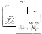
- Fig.1 is a diagram showing a concept of motion compensation in a moving picture.
- a subject Car in a reference picture signal Ref and a subject CurCar in an inputted picture signal Img are the same subject.
- a subject represented by a broken line in the picture signal Img indicates the position of the subject in the reference picture signal Ref.
- a picture coding apparatus codes a pixel block CurBlk within the picture signal Img
- higher prediction efficiency can be achieved by using, as a predictive picture signal Pred, pixels of a predictive picture block PredBlk in the reference picture signal Ref which indicates the same image as the subject CurCar and which indicates an image at a position corresponding to the position of the subject in the picture of the subject CurCar.
- a motion parameter signal MotionParam Information required for mapping from the pixel position of the predictive picture block PredBlk to the pixel position of the pixel block CurBtk is referred to as a motion parameter signal MotionParam.
- MotionParam MPEG-1, 2 and 4, and H.261 and H263, for example, employ a motion vector representing parallel movements of blocks.
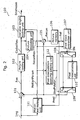
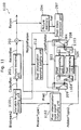
- Fig.2 is a block diagram showing the configuration of an existing picture coding apparatus 100.
- Such picture coding apparatus 100 is comprised of a differential calculator 101, a picture coding unit 102, a variable length coding unit 103, a picture decoding unit 104, an adder 105, a picture memory 106, a pixel block extraction unit 107, a switch 108, a switch 109, a pixel interpolating unit 110, a motion estimating unit 111, and a pixel interpolation applying judging unit 112.
- the picture coding apparatus 100 acquires a picture signal Img from outside.
- the differential calculator 101 outputs a differential picture signal Res which is the differential of pixel values between the picture signal Img inputted from outside and a predictive picture signal Pred acquired from a reference picture signal Ref.
- the predictive picture signal Pred which is an already coded picture, is a picture which has been decoded by the picture decoding unit 104, interpolated by the pixel interpolating unit 110 according to necessity, and extracted on a per block basis according to a motion vector from the motion estimating unit 111.
- the picture coding unit 102 codes the differential picture signal Res, and outputs a coded differential picture signal CodedRes. Since inter picture motion compensation is not conducted in the case of intra picture coding, the pixel value of a predictive picture is regarded as "0"..
- the variable length coding unit 103 performs variable length coding for the coded differential picture signal CodedRes and a motion parameter signal MotionParam, and outputs them to outside the picture coding apparatus 100 as a single coded signal Bitstream.
- the picture decoding unit 104 decodes the coded differential picture signal CodedRes and outputs a decoded differential picture signal ReconRes in order to utilize it as a reference picture in motion estimation.
- the adder 105 adds pixel values of the decoded differential picture signal ReconRes and of the predictive picture signal Pred, and outputs the result as a decoded picture signal Recon.
- Such decoded picture signal Recon is stored in the picture memory 106 and used as a reference picture when the following pictures are coded.
- the picture memory 106 holds some of coded pictures outputted from the adder 105 as reference picture signals Ref for prediction purposes.
- the pixel block extraction unit 107 extracts a pixel block Blk from a picture stored in the picture memory 106 serving as a reference picture, and outputs it to the switch 108.
- the switch 108 makes a switch between a terminal "1" and a terminal "2" according to an interpolation judgment signal UsePolator from the pixel interpolation applying judging unit 112.
- the terminal "1” is connected to a terminal "1" of the switch 109, and the terminal "2" is connected to the pixel interpolating unit 110.
- the pixel interpolating unit 110 When the amount of block movement indicated by a motion vector includes the amount of movement in a unit smaller than an integer pixel, the pixel interpolating unit 110 generates the pixel value of the position corresponding to it, and outputs such value to the terminal "2" of the switch 109.
- the switch 109 makes a connection by switching between the terminal "1" and the terminal "2" according to the interpolation judgment signal UsePolator from the pixel interpolation, applying judging unit 112.
- the motion estimating unit 111 determines a motion parameter signal MotionParam from the picture signal Img inputted from outside and the reference picture signal Ref.
- the pixel interpolation applying judging unit 112 judges whether to perform pixel interpolation or not when generating a predictive picture signal Pred from the reference picture signal Ref, according to the motion parameter signal MotionParam determined by the motion estimating unit 111.
- pixel interpolation is generally employed for calculating pixel values of a predictive picture which includes motion in a unit smaller than an integer pixel.
- Such pixel interpolation is conducted by applying filtering for pixel values of a reference picture by means of linear filtering.
- An increased number of taps in such linear filtering realizes a filter with desirable frequency properties, resulting in higher prediction efficiency as well as in a larger processing amount.
- a smaller number of filter taps leads to a filter with undesirable frequency properties, resulting in lower prediction efficiency as well as in a smaller processing amount.
- the pixel interpolation applying judging unit 112 judges whether to perform pixel interpolation or not in generating a predictive picture, according to the motion parameter MotionParam.
- the motion parameter signal MotionParam includes the amount of movement in a unit smaller than an integer pixel
- the pixel interpolation applying judging unit 112 judges that pixel interpolation is to be employed, and outputs a pixel interpolation use control signal UsePolator of the value "1".
- the motion parameter signal MotionParam indicates motion in integer pixel units, it is judged that pixel interpolation should not be employed, and a pixel interpolation use control signal UsePolator of the value "0" is outputted.
- a pixel interpolation use control signal UsePolator When a pixel interpolation use control signal UsePolator is "0", the switch 108 and the switch 109 make a switch to the terminals "1", and when a pixel interpolation use control signal' UsePolator is "1", the switch 108 and the switch 109 make a switch to the terminals "2".
- the pixel interpolating unit 110 is used when the switch 108 and the switch 109 are connected to the terminals "2" so as to perform pixel interpolation for a pixel block Blk to be used as a predictive picture signal Pred.
- the switch 108 and the switch 109 are "0", pixel interpolation is not to be conducted, and a pixel block Blk is used as a predictive picture signal Pred as it is.
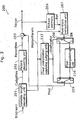
- Fig.3 is a block diagram showing the configuration of an existing picture. decoding apparatus 200.
- the picture decoding apparatus 200 acquires the coded signal Bitstream from outside.
- a variable length decoding unit 201 performs variable length decoding for the coded signal Bitstream so as to demultiplex it into coded differential picture signals CodedRes and motion parameter signals MotionParam.
- a picture decoding unit 202 decodes a coded differential picture signal CodedRes, and outputs it as a decoded differential picture signal ReconRes.
- An adder 203 adds the predictive picture signal Pred with the decoded differential picture signal ReconRes, and outputs the result as a decoded picture signal Recon.
- decoded picture signals Recon are to be stored in a picture memory 204 as reference picture signals Ref.
- a pixel block extraction unit 207 extracts a combination of pixels from a position, within a reference picture signal Ref, indicated by the motion parameter signal MotionParam (there is a case, however, where an area larger than an actual prediction block is extracted due to interpolation processing).
- a pixel interpolation applying judging unit 212 judges whether to employ pixel interpolation or not for the acquisition of a predictive picture, according to the motion parameter signal MotionParam. For example, when a motion vector indicates a parallel movement of a pixel block as in the case of MPEG-1, 2 and 4, it is possible to judge whether to use pixel interpolation or not according to whether such motion vector can be divided by an integer or' not.
- the pixel interpolation applying judging unit 212 outputs a pixel interpolation use control signal UsePolator of the value "1" when judging that pixel interpolation should be used, and outputs a pixel interpolation use control signal UsePolator of the value "0" when judging that pixel interpolation should not be used.
- the present invention aims at providing a picture coding method and a picture decoding method capable of selecting a different pixel interpolation method depending on a picture signal to be coded.
- the picture coding method is a picture coding method that uses pixel interpolation for generating a predictive picture comprising: a selecting step for selecting one pixel interpolation method from a plurality of pixel interpolation methods; and a pixel value generating step' for generating a pixel value corresponding to a target pixel position using the selected pixel interpolation method.
- the picture coding apparatus of the present invention it is possible to generate a coded signal appropriate to the processing power of a picture coding apparatus and the processing power of a picture decoding apparatus that receives the coded signal, by selecting one pixel interpolation method from the plurality of pixel interpolation methods.
- another picture coding apparatus is a picture coding method for performing pixel interpolation for a decoded picture and generating a predictive picture comprising: a decoding step for decoding an input coded signal; a storing step for storing the decoded picture decoded in the decoding step; a selecting step for selecting a pixel interpolation method involving a light power processing load from a plurality of pixel interpolation methods, when the decoded picture is a picture not to be referred to by other pictures; and a predictive picture generating step for generating the predictive picture using the selected pixel interpolation method.
- another picture coding apparatus is a picture coding method for performing pixel interpolation for a decoded picture and generating a predictive picture comprising: a decoding step for decoding an input coded signal; a storing step for storing the decoded picture decoded in the decoding step; a selecting step for selecting a pixel interpolation method involving a light power processing load from a plurality of pixel interpolation methods, when the decoded picture is a B picture which refers to a plurality of pictures; and a predictive picture generating step for generating the predictive picture using the selected pixel interpolation method.
- another picture coding apparatus is a picture coding method for performing pixel interpolation for a decoded picture and generating a predictive picture comprising: a decoding step for decoding an input coded signal; a storing step for storing the decoded picture decoded in the decoding step; a selecting step for selecting a pixel interpolation method involving a lighter power processing load from a plurality of pixel interpolation methods than in a case of a P picture which refers to one picture, when the decoded picture is a B picture which refers to a plurality of pictures; and a predictive picture generating step for generating the predictive picture using the selected pixel interpolation method.
- the picture decoding method is a picture decoding method for performing pixel interpolation for a decoded picture and generating a predictive picture comprising:..a selecting step for selecting a pixel interpolation method involving a light power processing load from a plurality of pixel interpolation methods, when the decoded picture to be obtained as a result of decoding an input coded signal is a picture not to be referred to by another decoded picture to be obtained as a result of decoding the coded signal; and a predictive picture generating step for generating the predictive picture using the selected pixel interpolation method.
- a pixel interpolation method involving a light power processing load is selected for a picture no to be referred to by other pictures, other pictures are not effected by the degradation of picture quality caused by generating a pixel value by the use of.a pixel interpolation method which involves a light power processing load for a predictive picture to be generated using such picture, and reduction can be made in power processing load in picture decoding processing from an overall point of view.
- another picture decoding method is a picture decoding method for performing pixel interpolation for a decoded picture and generating a predictive picture comprising: a selecting step for selecting a pixel interpolation method involving a light power processing load from a plurality of pixel interpolation methods, when the decoded picture to be obtained as a result of decoding an input coded signal is a B picture which refers to a plurality of pictures; and a predictive picture generating step for generating the predictive picture using the selected pixel interpolation method.
- the picture coding method and the picture decoding method according to the present invention is a picture decoding method for performing pixel interpolation for a predictive picture comprising: a selecting step for selecting a pixel interpolation method involving a light power processing load from a plurality of pixel interpolation methods, when a plurality of pictures are referred to for prediction; and a predictive picture generating step for generating a pixel value of the predictive picture using the selected pixel interpolation method.
- the picture coding apparatus and the picture decoding apparatus of the present invention since a pixel interpolation method involving a light power processing load is selected when the number of pictures to be referred to for prediction is more than one and when a prediction involving a heavy power processing load is carried out, reduction can be made in the power processing load of the picture coding and picture decoding of such picture, and power processing load in picture coding and picture decoding processes can be smoothed as a whole.
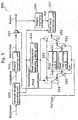
- Fig.4 is a block diagram showing the configuration of a picture coding apparatus 400 according to the present invention. Note that the same reference numbers are assigned to the same constituent elements which operate in the same manner and the same signals as those of the existing picture coding apparatus 100 illustrated in Fig.2, and explanations thereof are omitted.
- the picture coding apparatus 400 is a picture coding apparatus for selectively performing pixel interpolation of different degrees of accuracy according to a picture type signal PicType to be inputted from outside, and is comprised of the differential calculator 101, the picture coding unit 102, the variable length coding unit 103, the picture decoding unit 104, the adder 105, the picture memory 106, the pixel block extraction unit 107, the switch 108, the switch 109, a switch 401, a switch 402, a pixel interpolating unit A403, a pixel interpolating unit B404, the motion estimating unit 111, and the pixel interpolation applying judging unit 112.
- the picture coding apparatus 400 acquires a picture signal Img including a picture type signal PicType from outside.
- values "2", "1" and “0" indicating picture type signals PicType are values which are defined only for explanation purposes, and therefore that any value can substitute them as long as a distinction can be made between a plurality of pixel interpolation methods by such value.
- Fig.5 is a block diagram showing the configuration of a picture decoding apparatus 500 according to the present invention. Note that, in this diagram, since explanations are already given for constituent elements equivalent to those of the picture decoding apparatus 200 illustrated in Fig.3, the same numbers are assigned to such constituent elements and explanations thereof are omitted.
- the picture decoding apparatus 500 is a picture decoding apparatus that decodes a coded signal Bitstream in which different pixel interpolation methods are used on a per picture type basis, and is comprised of a variable length decoding unit 505, the picture decoding unit 202, the adder 203, the picture memory 204, the pixel block extraction unit 207, the switch 208, the switch 209, the pixel interpolation applying judging unit 212, a switch 501, a switch 502, a pixel interpolating unit A503, and a pixel interpolating unit B504.
- variable length decoding unit 505 performs variable length decoding for the coded signal Bitstream inputted from outside, demultiplexes picture type signals PicType, coded differential picture signals CodedRes, and motion parameter signals MotionParam from the coded signal Bitstream for which variable length decoding has been performed, and outputs the picture type signals PicType to the switch 501 and the switch 502, the motion parameter signals MotionParam to the pixel interpolation applying judging unit 212 and the pixel block extraction unit 207, and the coded differential picture signals CodedRes to the picture decoding unit 202 respectively.
- the switch 501 and the switch 502 make a switch to the terminals "1", . and pixel interpolation by the pixel interpolating unit A503 is performed.
- pixel interpolation by the pixel interpolating unit A503 is employed for a pixel block signal Blk.
- a simplified interpolation method with a small number of filter taps of "4", for example, is employed.
- a B picture since a B picture generates a predictive picture by referring to two pictures at the same time, pixel interpolation is required for each picture to be referred to. Accordingly, the amount of computation required for pixel interpolation doubles as compared to a P picture which refers to only one picture, meaning that the use of a simplified interpolation method for a B picture is effective also in that the amount of computation required for each picture can be smoothed. Therefore, it is useful if a simplified interpolation method is also used for a B picture to be referred to by other pictures.
- the picture decoding apparatus 500 when decoding a bit stream in which a single pixel interpolation filter is used in a picture coding apparatus for both P and B pictures, it is possible for the picture decoding apparatus 500 to use a simplified pixel interpolation filter only for a B picture.
- a pixel interpolation filter for a B picture is different from a pixel interpolation filter used in the picture coding apparatus, there occurs the degradation in the picture quality of the B picture.
- a B picture is not much referred to by other pictures, there are fewer cases where the degradation in picture quality propagates to the following pictures, as compared to.the case where the degradation in picture quality of a P picture occurs.
- the same pixel interpolation filter as used in the picture coding apparatus is not implemented in the picture decoding apparatus 500, it is possible to use a pixel interpolation filter whose number of taps is smaller than and closest to that of a pixel interpolation fitter used in the picture coding apparatus instead. In such case, there occurs picture quality degradation because of the fact that a pixel interpolation filter different from a pixel interpolation fitter used in the picture coding apparatus is used, but it is possible to carry on the decoding of the bit stream.
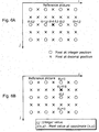
- Fig.6A is a diagram showing an example method for calculating, in a half pixel filter, the pixel value of a pixel which is located at a position half pixel off a real (an actually decoded) pixel in the direction of i axis.
- Fig.6B is a diagram showing an example method for calculating, in a half pixel filter, the pixel value of a pixel which is located at a position half pixel off a real (an actually decoded) pixel in the direction of j axis.
- ⁇ indicates a pixel at integer position
- ⁇ indicates a pixel at decimal position.
- i and j are integers.
- I(x, y) indicates a pixel value at coordinate (x, y).
- a half pixel filter can be embodied by software, an integrated circuit and the like capable of calculating pixel values of pixels at decimal position, indicated by ⁇ , which do not actually exist, according to pixel values of pixels at integer position indicated by O.
- Fig.6A explains the case where a pixel value I (i-0.5, j) of the pixel located at coordinate (i-0.5, j) is determined.
- a pixel value I (i-1, j) and a pixel value I (i, j) of the two adjacent pixels in the direction of i axis are utilized for the pixel located at coordinate (i-0.5, j).
- the pixel value I (i-0.5, j) can be represented as follows using Equation 1, which is the sum of products of pixel values in the direction of axis:
- Equation 1 a k indicates a filter factor, while trunc(n) indicates the truncation of the fractional portion of n.
- the pixel value I (i-0.5, j) of the pixel located at a half pixel position (i-0.5, j) can be determined as an average value of N pixel values of pixels on both sides of it.
- a pixel value I (i-2, j) and a pixel value I (i+1, j) of the pixels on both sides in the direction of i axis in addition to the pixel value I (i-1, j) and the pixel value I (i, j) of the two adjacent pixels in the direction of i axis, are further utilized for the pixel located at (i-0.5, j).
- the pixel value I (i-0.5, j) of the pixel located at a half pixel position (i-0.5, j) can be easily determined by substituting such values into N in Equation 1.
- Fig.6B explains the case where a pixel-value I (i, j-0.5) of the pixel located at coordinate (i, j-0.5) is determined. In other words, this is the case where a predictive picture moves in the direction of j axis in the reference picture by the amount of a sub pixel.
- M is an even natural number
- a pixel value I (i, j-1) and a pixel value I (i, j) of the two adjacent pixels. in the direction of j axis are utilized for the pixel value located at coordinate (i, j-0.5).
- the pixel value I (i, j-0.5) can be represented as follows using Equation 2, which is the sum of products of pixels values in the direction of j axis:
- Equation 2 a m indicates a filter factor. Likewise, when the number of taps increases to "4", "6" and "8", the pixel value of the pixel located at coordinate (i, j-0.5) can be easily determined by substituting such values into M in Equation 2.
- a pixel value I (i-0.5, j-0.5) located at coordinate (i-0.5, j-0.5) in the predictive picture can be represented as follows using Equation 3, which is the sum of products of pixel values in the direction of i axis and the direction of j axis:
- a pixel filter which realizes a pixel interpolating unit A and a pixel interpolating unit B offers higher prediction accuracy as the number of filter. taps increases, while the amount of computation processing becomes larger and power processing load on the picture coding apparatus becomes heavier.
- a plurality of pixel interpolating units of different prediction performance/processing amount can be employed as pixel interpolating units of the picture coding apparatus 400 and the picture decoding apparatus 500.
- the advantage of using pixel. interpolating units of different prediction performance/processing amount is described below. In order to make an explanation easier, assume that the pixel interpolating units A is capable of handling the amount of processing smaller than that of the pixel interpolating unit B, and that the pixel interpolating units B offers higher predication efficiency than that of the pixel interpolating unit A.
- a picture decoding apparatus that decodes a coded signal outputted by the picture coding apparatus according to the present invention
- two types of picture decoding apparatuses are assumed: a picture decoding apparatus equipped only with the pixel interpolating unit A and a picture decoding apparatus equipped with both the pixel interpolating until A and the pixel interpolating unit B.
- the former picture decoding apparatus is suitable for a device which is required to handle a small amount of processing and which has low processing power.
- the latter picture decoding apparatus is suitable for a device which handles a large amount of processing.
- the latter picture decoding apparatus is capable of decoding coded signals for which both the pixel interpolating unit A and the pixel interpolating unit B have been utilized, and providing upward compatibility with the former picture decoding apparatus. As the above explanation shows, by selecting a pixel interpolating unit of appropriate prediction performance/processing amount depending on a picture decoding apparatus, it becomes possible to employ the coding method to a wide variety of devices.
- pixel interpolating units are switched on a per picture basis according to picture properties, with a plurality of pixel interpolating units suited for pictures of specific properties available. For example, when edge information is important such as in the case of characters, a pixel interpolating unit with a superior capability of storing edge is used. If a plurality of pixel interpolating units can be switched, it becomes possible to select a pixel interpolating unit appropriate to the properties of a picture, resulting in increased prediction efficiency.
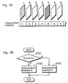
- Fig.7A is a diagram showing a relationship between the picture type of each of the pictures representing a moving picture and pixel interpolation methods.
- Fig.7B is a flowchart showing the procedure of selecting an interpolation method in the picture coding apparatus 400 and the picture decoding apparatus 500 according to the present invention.
- picture type signals PicType indicating whether each picture is an I picture, a B picture, or a P picture are provided, from outside, to the picture coding apparatus 400.
- the pixel values of a predictive picture is "0" since intra picture coding is performed. Therefore, the pixel interpolation applying judging unit 112 switches the switch 108 and the switch 109 to the terminals "1", and does not perform pixel interpolation itself.
- the switch 401 and the switch 402 are switched to the terminals "1" according to the value indicated by a picture type signal PicType, and a simple pixel interpolation A by the pixel interpolating unit A403 is used.
- the switch 401 and the switch 402 are switched to the terminals "2" according to the value indicated by a picture type signal PicType, and a highly accurate pixel interpolation B by the pixel interpolating unit B404 is used.
- the picture coding apparatus 400 performs a selection process illustrated in the flowchart of Fig. 7B.
- the switch 401 and the switch 402 make a judgment on whether the value of a picture type signal PicType to be inputted is a value indicating a B picture or not (S701), and if such value indicates a B picture, select the interpolation method A to be performed by the pixel interpolating unit A403 by getting connected to the respective terminals "1" (S702).
- the switch 401 and the switch 402 select the interpolation method B to be performed by the pixel interpolating unit B404 by getting connected to the respective terminals "2" (S703).
- the picture coding apparatus 400 repeats the processing from the above steps S701 to S703 for each picture of the picture signal Img to be inputted.
- a pixel interpolating unit that places a lighter power processing load is selected for a B picture which usually involves a comparatively heavy power processing load in picture coding processing, it becomes possible even for a picture coding apparatus with comparatively low processing power to carry out pixel interpolation.
- a pixel interpolating unit of lower accuracy is selected for a B picture which is less frequently referred to by other pictures, it is possible to restrain the influence of selecting a pixel interpolating unit of lower accuracy from propagating over other pictures.
- a selection of a pixel interpolating unit is usually made on the basis of a picture type signal PicType included in a picture signal, it is not necessary for a coded signal Bitstream to include information indicating which pixel interpolating unit is used for which picture, resulting in a reduced amount of processing to be performed by the variable length coding unit. Furthermore, since a pixel interpolating unit that involves a large amount of processing but that offers higher prediction accuracy is selected for a P picture which usually places a smaller processing amount on the picture coding apparatus, it is possible even for a picture coding apparatus with comparatively small processing power to perform pixel interpolation of higher accuracy. Moreover, since it is possible to perform pixel interpolation of higher prediction accuracy for a P picture to be referred to by other pictures, the degradation in picture quality can be minimized.
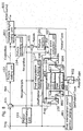
- Fig. 8 is a block diagram showing the configuration of a picture coding apparatus 800 that makes a switch of pixel interpolation methods on a per picture basis.
- the same numbers are assigned to the same constituent elements and the same signals as those of the picture coding apparatus 100 illustrated in Fig.2 and the picture coding apparatus 400 illustrated in Fig.4, and explanations thereof are omitted.
- the picture coding apparatus 800 is comprised of the differential calculator 101, the picture coding unit 102, the picture decoding unit 104, the adder 105, the picture memory 106, the pixel block extraction unit 107, the switch 108, the switch 109, the motion estimating unit 111, the pixel interpolation applying judging unit 112, the pixel interpolating unit A403, the pixel interpolating unit B404, a pixel interpolation switch position judging unit 801, a switch 802, a variable length coding unit 803, a switch 804 and a switch 805. If detecting from an inputted picture signal Img a unit (e.g.
- the pixel interpolation switch position judging unit 801 turns the switch 802 ON (in the conduction state) by outputting a pixel interpolation control Signal SetPolatorType"1".
- the switch 802 is switched, with a picture of the picture signal Img as a unit of switching pixel interpolation methods.
- the switch 802 has a functionality of letting a pixel interpolation type signal PolatorType into the switch 804 and the switch 805 only for a short period of time during which the top of each picture serving as a unit of switching comes, and interrupting a pixel interpolation type signal PolatorType from being inputted to the switch 804 and the switch 805 during the period of time other than the aforementioned unit of switching.
- This functionality is intended for preventing switching from being made between the pixel interpolating unit A403 and the pixel interpolating unit B404 while coding is being performed for the unit of switching.
- pixel interpolation type signal PolatorType is a signal to be inputted from outside in order to select a type of pixel interpolation according to power processing load on the picture coding apparatus 800 to be measured with the amount of remaining data and the like in a transmission buffer in the picture coding apparatus 800 not illustrated in the diagram as a guide, or to the decoding capabilities that a picture decoding apparatus is assumed to have.
- the switch 802 opens its terminal to turn to OFF, and turns to ON when the pixel interpolation switch control signal SetPolatorType"1" is inputted again. Furthermore, once a pixel interpolation type signal PolatorType is inputted from outside via the switch 802, the switch 804 and the' switch 805 remain to be connected to a connection terminal indicated by the value of such Pixel interpolation type signal PolatorType until another pixel interpolation type signal PolatorType of a different value is inputted.
- pixel interpolation utilizing switch judgment is carried out by selectively applying a filter on a per picture basis, from among a plurality of pixel interpolation methods, which provides optimal prediction efficiency within the limit of the processing amount.
- switch judgment when processing power of a picture coding apparatus becomes deficient while each picture is being coded, switching may be made at the next picture to a pixel interpolation method which requires a small amount of processing. Consequently, another pixel interpolating unit is selected according to a pixel interpolation type signal PolatorType.
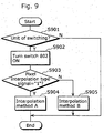
- Fig.9 is a flowchart showing the procedure of selecting an interpolation method in the picture coding apparatus 800. More specifically, the picture coding apparatus 800 performs a selection process illustrated in the flowchart of Fig.9 by connecting the switch 802 according to the value of a pixel interpolation switch control signal SetPolatorType and making a switch between the switch 804 and the switch 805 according to the value of a pixel interpolation type signal PolatorType to be inputted from outside while the switch 802 is connected.
- the picture coding apparatus 800 detects a picture header and the like indicating the top of each picture from the picture signal Img (S901), and outputs, through the pixel interpolation switch position judging unit 801, a pixel interpolation switch control signal "1", for example, so as to turn the switch 802 ON (S902).
- the picture coding apparatus 800 judges whether or not the value of the pixel interpolation type signal inputted while the switch is ON is "1" (S903), and connects the switch 804 and the switch 805 to the respective terminals "1", when the value is "1", so as to select the interpolation method A to be conducted by the pixel interpolating unit A403 (S904).
- the switch 804 and the switch 805 are connected to the respective terminals "2", and the interpolation method B by the pixel interpolating unit B404 is selected (S905).
- the picture coding apparatus 800 repeats the processing from the above steps S901 to S905 for each picture of the picture signal Img to be inputted.
- the picture coding apparatus 800 When a picture is employed as the unit of switching pixel interpolation types in the variable length coding unit 803, the picture coding apparatus 800 further records the value of a pixel interpolation type signal PolatorType on each picture of the coded signal Bitstream to be outputted by the picture coding apparatus 800, e.g., on each picture header of such coded signal Bitstream, and outputs it.
- Fig.10A is a diagram showing the stream structure of the coded signal Bitstream according to the present invention.
- Fig.10B is a diagram showing a coded signal Bitstream in the case where pixel interpolation methods are switched on a per picture basis.
- the coded signal according to the present invention is characterized by that a pixel interpolation type signal PolatorType is included in the coded signal Bitstream.
- a pixel interpolation type signal PolatorType is included in the coded signal Bitstream.
- a pixel interpolation type signal PolatorType indicating an interpolation method used for performing pixel interpolation for each picture
- a header 1001 e.g. diagonally shaded part
- a picture header 1002 e.g. diagonally shaded part
- the picture decoding apparatus by storing a pixel interpolation type signal PolatorType in the header 1001 which is the head of the coded signal Bitstream or picture headers 1002 which are the heads of random access points, it becomes possible for the picture decoding apparatus to identify the pixel interpolation type of a picture before decoding such picture, by inputting a coded signal Bitstream from the header 1001 or an access point.
- the pixel interpolating units may be switched not only for each picture but also for each picture area smaller than a picture (any area made up of a combination of more than one pixel, e.g., slice/macroblock/block of MPEG, would be acceptable).
- the values of pixel interpolation type signals PolatorType corresponding to each slice may be described in the header to be provided for the whole coded signal Bitstream, or may be collectively described in picture headers on a per picture basis.
- the' value of a pixel interpolation type signal of each slice may be described in the slice header of each slice.
- the value of a pixel interpolation type signal of each macroblock or block may be collectively described in the slice header of each slice.
- existing picture coding methods include coding methods in which pixel interpolation methods for generating the pixel value corresponding to a position in a predictive picture signal are switched depending on such position in the predictive picture signal.
- Such coding methods for instance, are one in which a pixel interpolation method for a half pixel position is selected when generating a pixel value corresponding to a half pixel position, and one in which a pixel interpolation method for a quarter pixel position is selected when generating a pixel value corresponding to a quarter pixel position.
- the coding method according to the present invention is different in that a plurality of pixel interpolating units are available for each calculation of the pixel value corresponding to a single position in a predictive picture signal, and therefore a plurality of pixel interpolation methods are freely selected for calculating the pixel value corresponding to a single pixel position.
- the picture coding method of the present invention may be combined with the above methods in which a plurality.of pixel interpolation methods are switched for various pixel positions.
- a plurality of pixel interpolating units for calculating each pixel value corresponding to various pixel positions, as well as a plurality of pixel interpolating units of different prediction accuracy for calculating the pixel value for a single pixel position are provided.
- Fig.11 is a block diagram showing the configuration of another picture decoding apparatus 1100 according to the present embodiment.
- the picture decoding apparatus 1100 is comprised of the picture decoding unit 202, the adder 203, the picture memory 204, the pixel block extraction unit 207, the switch 208, the switch 209, the pixel interpolation applying judging unit 212, the pixel interpolating unit A503, the pixel interpolating unit B504, a variable length decoding unit 1101, a pixel interpolation type changing unit 1102, a switch 1103, and a switch 1104.
- the coded signal Bitstream2 outputted by the picture coding apparatus 800 illustrated in Fig.8 is inputted to the picture decoding apparatus 1100.
- pixel interpolation type signals PolatorType1 are described in the coded signal Bitstream2 to be inputted to the picture decoding apparatus 1100.
- the picture decoding apparatus 1100 is characterized by that, when the picture decoding apparatus 1100 is not equipped with a pixel interpolating unit indicated by a pixel interpolation type signal PolatorType1 in the coded signal Bitstream2, it uses instead either of the pixel interpolating units that the picture decoding apparatus 1100 has.
- the variable length decoding unit 1101 performs variable length decoding for the coded signal Bitstream2, and demultiplexes it into the coded differential picture signals CodedRes, the motion parameter signals MotionParam, and the pixel interpolation type signals PolatorType1.
- the pixel interpolation type changing unit 1102 holds inside it an interpolation type table which is prepared in advance and which indicates types of the pixel interpolating units which would be specified by the pixel interpolation type signals PolatorType1, parameters indicating the characteristics of each of such pixel interpolating units, and whether the pixel interpolating units are implemented or not. On the basis of such interpolation type table, the pixel interpolation type changing unit 1102 judges whether a pixel interpolating unit indicated by the value of a pixel interpolation type signal PolatorType1 is implemented or not in the picture decoding apparatus 1100.
- Fig.12 is a diagram showing an example of an interpolation type table 1200 which the pixel interpolation type changing unit 1102 illustrated in Fig.11, holds.
- the interpolation type table 1200 describes implementation /non-implementation 1201 of each pixel interpolating unit indicated by the values of the pixel interpolation type signals PolatorType1, values of the pixel interpolation type signals PolatorType1 1202, and filter tap number (N) 1203 indicating the characteristics of each pixel interpolating unit indicated by the value of a pixel interpolation type signal PolatorType1.
- the effect of being able to decode an input coded signal Bitstream without any problem can be achieved, even when the coded signal Bitstream which includes a pixel interpolation type signal PolatorType2 indicating a pixel interpolating unit not implemented in the picture decoding apparatus 1100 is inputted. Meanwhile, when the picture decoding apparatus 1100 has only one pixel interpolating unit, an input coded signal Bitstream can be decoded by forcedly using such pixel interpolating unit. Furthermore, although the picture decoding apparatus 1100 according to the present embodiment includes two pixel interpolating units, an equivalent processing can be performed even if there are three or more pixel interpolating units.
- the picture decoding apparatus 1100 makes a switch of pixel interpolating units at the point in time when a pixel interpolation type is switched, as presented in the first embodiment.
- the characteristics of a plurality of pixel interpolating units are indicated here by the number of fitter taps, it does not necessarily have to be filter tap numbers, and therefore other parameters can substitute them.
- the picture decoding apparatus 1100 has all pixel interpolation filters which are possible to be employed by the picture coding apparatus, the pixel interpolating type changing unit 1102 of the picture decoding apparatus 1100 can be omitted. In such a case, a pixel interpolation type signal PolatorType1 will be used as it is as a pixel interpolation type signal PolatorType2.
- Fig.13 is a block diagram showing the configuration of a picture coding apparatus 1300 according to the second embodiment of the present invention. Note that the same reference numbers are assigned to the constituent elements which operate in the same manner and. the same signals as those in the picture coding apparatus 100, the picture coding apparatus 400, and the picture coding apparatus 800 illustrated in Fig.2, Fig.4 and Fig.8, and explanations thereof are omitted.
- the picture coding apparatus 1300 is a picture coding apparatus that uses a pixel interpolating unit which involves a smaller amount of processing in pixel interpolation when a picture to be' coded is a picture not to be referred to by other pictures, while using a pixel interpolating unit which offers high prediction efficiency but which involves a larger amount of processing in pixel interpolation when a picture to be coded is a picture not to be referred to by other pictures, and is comprised of the differential calculator 101, the picture coding unit 102, the picture decoding unit 104, the adder 105, the picture memory 106, the pixel block extraction unit 107, the switch 108, the switch 109, the pixel interpolation applying judging unit 112, a switch 1301, a switch 1302, a variable length coding unit 1303, a switch 1304, and a motion estimating unit 1305.
- reference instruction signals AvairableRef indicating whether or not pictures to be coded will be used later as reference pictures are inputted from outside.
- a reference instruction signal AvairableRef which is a signal to be inputted from outside according to a setting inputted by an operator of the picture coding apparatus 1300 using such an input unit as a keyboard not illustrated in the diagram, indicates that a picture to be coded is not to be used as a reference picture when its value is "0", while indicating that the picture to be coded is to be used later as a reference picture when its value is "1".
- the switch 1301 and the switch 1302 connect to the respective terminals "1", and select the pixel interpolating unit A403 which involves a smaller amount of processing.
- the switch 1301 and the switch 1302 connect to the respective terminals "2", and select the pixel interpolating unit B404 which offers high prediction efficiency but which involves a larger amount of processing.
- the switch 1304 turns to OFF when the value of a reference instruction signal AvairableRef is "0", and the decoded differential picture signal ReconRes of the above picture will not be stored in the picture memory 106.
- the switch 1304 turns to ON, and the decoded differential picture signal ReconRes of the above picture will be stored in the picture memory 106.
- variable length coding unit 1303 records and outputs the value of a reference instruction signal AvairableRef in each picture of a coded signal Bitstream3, e.g., in each picture header of the coded signal Bitstream3, which is an output of the picture coding apparatus 1300 and which has the stream structure illustrated in Fig.10.
- Fig.14 is a block diagram showing the configuration of a picture decoding apparatus 1400 for decoding the coded signal Bitstream3, which is an output of the picture coding apparatus 1300 illustrated in Fig. 13.
- the same reference numbers are assigned to such constituent elements, and explanations thereof are omitted.
- the picture decoding apparatus 1400 which is a picture decoding apparatus that decodes the coded signal Bitstream3 including the above-described reference instruction signals AvairableRef, is comprised of the picture decoding unit 202, the adder 203, the picture memory 204, the pixel block extraction unit 207, the switch 208, the switch 209, the pixel interpolation applying judging unit 212, a variable length decoding unit 1401, a switch 1402, a switch 1403 and a switch 1404.
- the variable length decoding unit 1401 performs variable length decoding for the inputted coded signal Bitstream3, and demultiplexes it into the coded. differential picture signals CodedRes, the motion parameter signals MotionParam, and the reference instruction signals AvairableRef.
- the demultiplexed reference instruction signals AvairableRef are inputted to the switch 1402, the switch 1403 and the switch 1404.
- the switch 1404 turns to OFF when the value of a reference instruction signal AvairableRef is "0", i.e., when the decoded image signal Recon of the picture will not be used as a reference picture. Therefore, the decoded image signal Recon of the picture will not be stored in the memory 204.
- the switch 1404 turns to ON.
- the decoded image signal Recon of the picture will be stored in the image memory 204.
- the switch 1402 and the switch 1403 connect to the respective terminals "1", and select the pixel interpolating unit A503 which involves a smaller amount of processing.
- the switch 1402 and the switch 1403 connect to the respective terminals "2", and select the pixel interpolating unit B504 which involves a larger amount of processing but which offers high prediction efficiency.
- the picture coding apparatus 1300 and the picture decoding apparatus 1400 are capable of minimize the degradation in predication accuracy and reducing the power processing load generated in picture coding processing.
- the switch 1404 and the decoded image signal Recon of a picture riot to be referred to by other pictures is not stored in the picture memory 204 in the image decoding apparatus 1400 according to the present invention, the above-explained other picture decoding apparatuses according to the present invention may also be equipped with the switch 1404.
- the pixel interpolating unit A403 and the. pixel interpolating unit. B404 are switched by switches and used, the present invention is .not limited to this and therefore, the pixel interpolating unit A403 and the pixel interpotating unit B404 may be substituted with a single pixel interpolating unit that operates in a plurality of operation modes.
- Such pixel interpolating unit is a single pixel filter for performing operations in accordance with a plurality of operation methods or a plurality of operation equations, depending on target prediction accuracy or power processing toad to be obtained, for example, and a single operation mode (operational method or a operational expression) is determined according to parameters to be provided from outside.
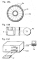
- Fig.15 is a diagram explaining the case where the processing is performed in a computer system using a flexible disk which stores the picture coding method or the picture decoding method of the above-described first to third embodiments.
- Fig.15B shows an external view of the flexible disk viewed from the front, a schematic cross-sectional view and the flexible disk
- Fig. 15A illustrates an example physical format of the flexible disk 1201 as a recording medium itself.
- a flexible disk FD is contained in a case F, a plurality of tracks Tr are formed concentrically on the surface of the disk in the radius direction from the periphery, and each track is divided into 16 sectors Se in the angular direction. Therefore, in the flexible disk storing the above-mentioned program, the picture coding method as such program is recorded in an area allocated for it on the flexible disk FD.
- Fig.15C shows the structure for recording and reading out the program on and from the flexible disk FD.
- the computer system Cs When the program is recorded on the flexible disk FD, the computer system Cs writes the picture coding method or the picture decoding method as a program via a flexible disk drive FDD.
- the picture coding method is constructed in the computer system by the program on the flexible disk, the program is read out from the flexible disk via the flexible disk drive and transferred to the computer system.
- the above explanation is made on the assumption that a recording medium is a flexible disk, but the same processing can also be performed using an optical disc.
- the recording medium is not limited to a flexible disk and an optical disc, and any other medium such as an IC card and a ROM cassette capable of recording a program can be used.
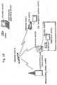
- Figs.16 to 19 are diagrams explaining a device for performing coding processing or decoding processing shown in the aforementioned embodiments as well as a system utilizing such device.
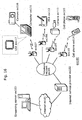
- Fig. 16 is a block diagram showing the overall configuration of a content supply system ex100 for realizing a content distribution service.
- the area for providing communication service is divided into cells of desired size, and base stations ex107 ⁇ ex110 which are fixed wireless stations are placed in respective cells.
- a computer ex111, a PDA (Personal Digital Assistant) ex112, a camera ex113, and a cell phone ex114 are connected to the Internet eX101 via an Internet service provider ex102 and a telephone network ex104.
- the content supply system ex100 is not limited to the configuration as shown in Fig. 16, and may be connected to a combination of any of them.
- each device may be connected directly to the telephone network ex104, not through the base stations ex107 ⁇ ex110 which are fixed wireless stations.
- the camera ex113 is a device such as a digital video camera capable of shooting moving pictures.
- the cell phone may be a cell phone of a PDC (Personal Digital Communication) system, a CDMA (Code Division Multiple Access) system, a W-CDMA (Wideband-Code Division Multiple Access) system or a GSM (Global System for Mobile Communications) system, a PHS (Personal Handyphone system) or the like.
- PDC Personal Digital Communication
- CDMA Code Division Multiple Access
- W-CDMA Wideband-Code Division Multiple Access
- GSM Global System for Mobile Communications
- PHS Personal Handyphone system
- a streaming server ex103 is connected to the camera ex113 via the base station ex109 and the telephone network ex104, which enables live distribution or the like using the camera ex113 based on coded data transmitted from the user using the camera ex113.
- Either the camera ex113 or the server and the like for carrying out data transmission may code the shot data.
- moving picture data shot by a camera ex116 may be transmitted to the streaming server ex103 via the computer ex111.
- the camera ex116 is a device such as a digital camera capable of shooting still pictures and moving pictures. In this case, either the camera ex116 or the computer ex111 may code the moving picture data.
- An LSI ex117 included in the computer ex111 and the camera ex116 performs coding processing.
- software for coding and decoding pictures may be integrated into a certain type of storage medium (such as a CD-ROM, a floppy disk and a hard disk) that is a recording medium readable by the computer ex111 or the like.
- a cell phone with a camera ex115 may transmit the moving picture data. This moving picture data is data coded by the LSI included in the cell phone ex115.
- Fig.17 is a diagram showing an example of the cell phone ex115.
- the cell phone ex115 has an antenna ex201 for transmitting/receiving radio waves to and from the base station ex110 via radio waves, a camera unit ex203 such as a CCD camera capable of shooting videos and still pictures, a display unit ex202 such as a liquid crystal display for displaying the data obtained by decoding videos and the like shot by the camera unit ex203 and decoding videos and the like received by the antenna ex201, a main body including a set of operation keys ex204, a voice output unit ex208 such as a speaker for outputting voices, a voice input unit ex205 such as a microphone for inputting voices, a recording medium ex207 for storing coded or decoded data such as data of moving or still pictures shot by the camera, data of received e-mails and moving picture data or still picture data, and a slot unit ex206 for enabling the recording medium ex207 to be attached to the cell phone ex115.
- a camera unit ex203 such as a CCD camera
- the recording medium ex207 stores in itself a flash memory element, a kind of EEPROM (Electrically Erasable and Programmable Read Only Memory) that is an electrically erasable and rewritable nonvolatile memory, in a plastic case such as a SD card.
- EEPROM Electrically Erasable and Programmable Read Only Memory
- content (such as a music live video) shot by the user using the camera ex113, the camera ex116 or the like is coded' in the same manner as the above-described embodiments and transmitted to the streaming server ex103, and the streaming server ex103 makes stream distribution of the content data to clients at their request.
- the clients include the computer ex111, the PDA ex112, the camera ex113, the cell phone ex114 and so on capable of decoding the above-mentioned coded data.
- the content supply system ex100 with the above structure is a system in which the clients can receive and reproduce the coded data, and further can receive, decode and reproduce the data in real time so as to realize personal broadcasting.
- Fig.18 is a block diagram showing the configuration of the cell phone ex115.
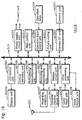
- a main control unit ex311 for overall controlling the display unit ex202 and each unit of the main body ex204 is configured in a manner in which a power supply circuit unit ex310, an operation input control unit ex304, a picture coding unit ex312, a camera interface unit ex303, an LCD (Liquid Crystal Display) control unit ex302, a picture decoding unit ex309, a multiplexing/demultiplexing unit ex308, a recording and reproducing unit ex307, a modem circuit unit ex306 and a voice processing unit ex305 are interconnected via a synchronous bus ex313.
- a power supply circuit unit ex310 an operation input control unit ex304, a picture coding unit ex312, a camera interface unit ex303, an LCD (Liquid Crystal Display) control unit ex302, a picture decoding unit ex309, a multiplexing/demultiplexing unit ex308, a recording and reproducing unit ex307, a
- the power supply circuit unit ex310 supplies to each unit with power from a battery pack so as to activate the digital cell phone with a camera ex115 for making it into a ready state.
- the voice processing unit ex305 converts voice signals received by the voice input unit ex205 in conversation mode into digital voice data under the control of the main control unit ex311 comprised of a CPU, a ROM, a RAM and others
- the modem circuit unit ex306 performs spread spectrum processing for it
- a transmit/receive circuit unit ex301 performs digital-to-analog conversion processing and frequency transform processing for the data, so as to transmit it via the antenna ex201.
- the transmit/receive circuit unit ex301 amplifies a received signal received by the antenna ex201 in conversation mode and performs frequency transform processing and analog-to-digital conversion processing for the data, the modem circuit unit ex306 performs inverse spread spectrum processing for the data, and the voice processing unit ex305 converts it into analog voice data, so as to output it via the voice output unit ex208.
- the text data of the e-mail inputted by operating the operation keys ex204 on the main body is sent out to the main control unit ex311 via the operation input control unit ex304.
- the modem circuit unit ex306 performs spread spectrum processing for the text data
- the transmit/receive circuit unit ex301 performs digital-to-analog conversion processing and frequency transform processing. for it, the data is transmitted to the base station ex110 via the antenna ex201.
- the picture data shot by the camera unit ex203 is supplied to the picture coding unit ex312 via the camera interface unit ex303.
- the picture data is not transmitted, it is also possible to display the picture data shot by the camera unit ex203 directly on the display unit 202 via the camera interface unit ex303 and the LCD control unit ex302.
- the picture coding unit ex312 compresses and codes the picture data supplied from the camera unit ex203 by the coding method presented in the above-mentioned embodiments so as to convert it into coded picture data, and sends it out to the multiplexing/demultiplexing unit ex308.
- the cell phone ex115 sends out the voices received by the voice input unit ex205 while the shooting by the camera unit ex203 is taking place, to the multiplexing/demultiplexing unit ex308 as digital voice data via the voice processing unit ex305.
- the multiplexing/demultiplexing unit ex308 multiplexes the coded picture data supplied from the picture coding unit ex312 and the voice data supplied from the voice processing unit ex305 by a predetermined method, the modem circuit unit ex306 performs spread spectrum processing for the resulting multiplexed data, and the transmit/receive circuit unit ex301 performs digital-to-analog conversion processing and frequency transform processing so as to transmit the processed data via the antenna ex201.
- the modem circuit unit ex306 When receiving data of a moving picture file which is linked to a Web page or the like in data communication mode, the modem circuit unit ex306 performs inverse spread spectrum processing for the data received from the base station ex110 via the antenna ex201, and sends out the resulting multiplexed data to the multiplexing/demultiplexing unit ex308.
- the multiplexing/demultiplexing unit ex308 separates the multiplexed data into coded picture data and voice data, and supplies the coded picture data to the picture decoding unit ex309 and the voice data to the voice processing unit ex305 via the synchronous bus ex313.
- the picture decoding unit ex309 decodes the coded picture data by the decoding method corresponding to the coding method as shown in the above-mentioned embodiments to generate reproduced moving picture data, and supplies 'this data to the display unit ex202 via the LCD control unit ex302, and thus moving picture data included in a moving picture file linked to a Web page, for instance, is displayed.
- the voice processing unit ex305 converts the voice data into analog voice data, and supplies this data to the voice output unit ex208, and thus voice data included in a moving picture file linked to a Web page, for instance, is reproduced.
- a coded bit stream of video information is transmitted to a satellite ex410 for communications, broadcasting or the like by radio waves.
- the broadcast satellite ex410 transmits radio waves for broadcasting
- an antenna ex406 of a house equipped with satellite broadcasting reception facilities receives the radio waves
- an apparatus such as a television ex401 and a set top box ex407 decodes the bit stream and reproduce the decoded data.
- the decoding method as shown in the above-mentioned embodiments can be implemented in the reproducing apparatus ex403 for reading off and decoding the codedbit stream recorded on a storage medium ex402 that is a recording medium.
- a reproduced video signal is displayed on a monitor ex404.
- the picture decoding apparatus in the set top box ex407 connected to a cable ex405 for cable television or the antenna ex406 for satellite/ground-based broadcasting so as to reproduce it on a television monitor ex408.
- the picture coding apparatus may be incorporated into the television, not in the set top box.
- a car ex412 having an antenna ex411 can receive a signal from the satellite ex410, the base station ex107 or the like for reproducing a moving picture on a display device such as a car navigation system ex413.
- the picture coding apparatus and the picture decoding apparatus according to the present invention are suited to be used as a picture coding apparatus and a picture decoding apparatus incorporated into a cell phone that transmits pictures, as well as a picture coding apparatus and a picture decoding apparatus equipped in a car navigation system. Furthermore, the present invention is suited for use as a program for carrying out the picture coding apparatus and the picture decoding apparatus of the present invention and as a recording medium that stores them. Also, the present invention is suitable as a recording medium that stores.coded signals generated by the picture coding apparatus of the present invention.
Landscapes
- Engineering & Computer Science (AREA)
- Multimedia (AREA)
- Signal Processing (AREA)
- Compression Or Coding Systems Of Tv Signals (AREA)
- Compression, Expansion, Code Conversion, And Decoders (AREA)
Applications Claiming Priority (5)
| Application Number | Priority Date | Filing Date | Title |
|---|---|---|---|
| JP2001283265 | 2001-09-18 | ||
| JP2001283265 | 2001-09-18 | ||
| JP2002109009A JP2003304538A (ja) | 2002-04-11 | 2002-04-11 | 画像符号化装置、画像復号化装置及びそれらの方法 |
| JP2002109009 | 2002-04-11 | ||
| PCT/JP2002/008227 WO2003030556A1 (en) | 2001-09-18 | 2002-08-12 | Image encoding method and image decoding method |
Publications (2)
| Publication Number | Publication Date |
|---|---|
| EP1432249A1 true EP1432249A1 (de) | 2004-06-23 |
| EP1432249A4 EP1432249A4 (de) | 2007-12-05 |
Family
ID=26622417
Family Applications (1)
| Application Number | Title | Priority Date | Filing Date |
|---|---|---|---|
| EP02758839A Ceased EP1432249A4 (de) | 2001-09-18 | 2002-08-12 | Bildkodierungsverfahren und bilddekodierungsverfahren |
Country Status (5)
| Country | Link |
|---|---|
| US (1) | US20040247190A1 (de) |
| EP (1) | EP1432249A4 (de) |
| KR (2) | KR100747958B1 (de) |
| CN (1) | CN1298171C (de) |
| WO (1) | WO2003030556A1 (de) |
Cited By (11)
| Publication number | Priority date | Publication date | Assignee | Title |
|---|---|---|---|---|
| WO2008084378A3 (en) * | 2007-01-09 | 2008-10-23 | Nokia Corp | Adaptive interpolation filters for video coding |
| WO2011130187A1 (en) * | 2010-04-12 | 2011-10-20 | Qualcomm Incorporated | Mixed tap filters |
| RU2491758C2 (ru) * | 2008-07-07 | 2013-08-27 | Квэлкомм Инкорпорейтед | Кодирование видеосигналов посредством выбора фильтра |
| RU2505938C2 (ru) * | 2008-04-10 | 2014-01-27 | Квэлкомм Инкорпорейтед | Интерполяция на основе искажений в зависимости от скорости передачи для кодирования видео на основе неперестраиваемого фильтра или адаптивного фильтра |
| RU2521081C2 (ru) * | 2008-07-11 | 2014-06-27 | Квэлкомм Инкорпорейтед | Фильтрация видеоданных с использованием множества фильтров |
| US8804831B2 (en) | 2008-04-10 | 2014-08-12 | Qualcomm Incorporated | Offsets at sub-pixel resolution |
| US8831086B2 (en) | 2008-04-10 | 2014-09-09 | Qualcomm Incorporated | Prediction techniques for interpolation in video coding |
| US8964852B2 (en) | 2011-02-23 | 2015-02-24 | Qualcomm Incorporated | Multi-metric filtering |
| US9014267B2 (en) | 2006-11-30 | 2015-04-21 | Ntt Docomo, Inc. | System and method for encoding and decoding with dynamic interpolation filter |
| US9143803B2 (en) | 2009-01-15 | 2015-09-22 | Qualcomm Incorporated | Filter prediction based on activity metrics in video coding |
| US9967590B2 (en) | 2008-04-10 | 2018-05-08 | Qualcomm Incorporated | Rate-distortion defined interpolation for video coding based on fixed filter or adaptive filter |
Families Citing this family (16)
| Publication number | Priority date | Publication date | Assignee | Title |
|---|---|---|---|---|
| JP4120301B2 (ja) * | 2002-04-25 | 2008-07-16 | ソニー株式会社 | 画像処理装置およびその方法 |
| EP3288261B1 (de) * | 2002-08-08 | 2019-11-06 | Godo Kaisha IP Bridge 1 | Dekodierungsverfahren für bewegte bilder |
| CN101848385B (zh) * | 2004-04-21 | 2012-10-10 | 松下电器产业株式会社 | 运动补偿装置 |
| EP1777965A1 (de) * | 2004-08-05 | 2007-04-25 | Matsushita Electric Industrial Co., Ltd. | Bilddecodierungseinrichtung und bildcodierungseinrichtung |
| WO2006057133A1 (ja) * | 2004-11-25 | 2006-06-01 | Matsushita Electric Industrial Co., Ltd. | 画像表示装置 |
| JP2006254231A (ja) * | 2005-03-11 | 2006-09-21 | Toshiba Corp | 情報処理装置および同装置で用いられるプログラム |
| KR100759870B1 (ko) * | 2006-03-24 | 2007-09-18 | 경희대학교 산학협력단 | Cbp에 기초하여 선택된 보간 필터를 이용하여 공간 계층 간의 예측을 수행하는 h.264 스케일러블 영상 부호화/복호화 방법 및 그 장치 |
| US8971412B2 (en) * | 2008-04-10 | 2015-03-03 | Qualcomm Incorporated | Advanced interpolation techniques for motion compensation in video coding |
| KR101377527B1 (ko) * | 2008-10-14 | 2014-03-25 | 에스케이 텔레콤주식회사 | 복수 개의 참조 픽처의 움직임 벡터 부호화/복호화 방법 및장치와 그를 이용한 영상 부호화/복호화 장치 및 방법 |
| US9788010B2 (en) | 2009-05-07 | 2017-10-10 | Texas Instruments Incorporated | Reducing computational complexity when video encoding uses bi-predictively encoded frames |
| ES2739475T3 (es) * | 2009-05-11 | 2020-01-31 | Ntt Docomo Inc | Dispositivo, método y programa de codificación de imágenes en movimiento, y dispositivo, método y programa de decodificación de imágenes en movimiento |
| JP5066232B2 (ja) * | 2010-07-28 | 2012-11-07 | 株式会社東芝 | 情報処理装置および画像処理方法 |
| WO2012134046A2 (ko) | 2011-04-01 | 2012-10-04 | 주식회사 아이벡스피티홀딩스 | 동영상의 부호화 방법 |
| BR122020011587B1 (pt) | 2011-11-08 | 2022-05-03 | Kabushiki Kaisha Toshiba | Método de decodificação realizado pelo menos parcialmente por um circuito eletrônico e método de codificação realizado pelo menos parcialmente por um circuito eletrônico |
| KR20150128664A (ko) * | 2013-01-09 | 2015-11-18 | 빈첸초 리구오리 | 픽셀의 2개의 블록을 비교하기 위한 방법 및 장치 |
| EP3298783B1 (de) * | 2016-04-15 | 2020-11-18 | Magic Pony Technology Limited | Bewegungskompensation mit verwendung von temporärer bildinterpolation |
Family Cites Families (22)
| Publication number | Priority date | Publication date | Assignee | Title |
|---|---|---|---|---|
| KR950006058B1 (ko) * | 1992-10-28 | 1995-06-07 | 주식회사금성사 | 슈도우메디안 필터를 이용한 주사선 보간기의 보간성분 발생기 |
| US5557331A (en) * | 1993-03-11 | 1996-09-17 | Matsushita Electric Industrial Co., Ltd. | Image encoding method, an image encoding circuit, an image encoding apparatus, and an optical disk |
| JPH06268992A (ja) * | 1993-03-15 | 1994-09-22 | Sony Corp | 画像符号化方法、画像復号化方法、画像符号化装置、画像復号化装置及び記録媒体 |
| JP3240737B2 (ja) * | 1993-03-19 | 2001-12-25 | ソニー株式会社 | 画像信号符号化方法、装置、復号化方法及び装置 |
| JP2963362B2 (ja) * | 1995-03-24 | 1999-10-18 | 株式会社グラフィックス・コミュニケーション・ラボラトリーズ | 階層型動きベクトル検出方法及びその装置 |
| DE19524808A1 (de) * | 1995-07-07 | 1997-01-09 | Thomson Brandt Gmbh | Verfahren, Encoder und Decoder zur Resynchronisierung auf einen fehlerbehafteten Datenstrom |
| US5757670A (en) * | 1995-07-28 | 1998-05-26 | S3, Incorporated | Frame reconstruction for video data compression |
| JP2868445B2 (ja) * | 1995-11-02 | 1999-03-10 | 株式会社グラフィックス・コミュニケーション・ラボラトリーズ | 動画像圧縮方法および装置 |
| JPH09322175A (ja) * | 1996-05-30 | 1997-12-12 | Sony Corp | 動画像復号化方法及び装置 |
| JPH09326958A (ja) * | 1996-06-05 | 1997-12-16 | Sony Corp | 画像処理装置および処理方法 |
| EP1193977B1 (de) * | 1997-06-09 | 2003-08-27 | Hitachi, Ltd. | Bildfolgekodierungsverfahren |
| ES2209041T3 (es) * | 1997-12-03 | 2004-06-16 | Fuji Photo Film Co., Ltd. | Procedimiento y aparato para la interpolacion de señales de imagen. |
| US6259734B1 (en) * | 1998-04-03 | 2001-07-10 | Matsushita Electric Industrial Co., Ltd. | Image processing method, image processing apparatus, and data storage media |
| JP3937599B2 (ja) * | 1998-07-23 | 2007-06-27 | ソニー株式会社 | 画像復号装置及び画像復号方法 |
| JP4026238B2 (ja) * | 1998-07-23 | 2007-12-26 | ソニー株式会社 | 画像復号装置及び画像復号方法 |
| AUPQ377599A0 (en) * | 1999-10-29 | 1999-11-25 | Canon Kabushiki Kaisha | Colour clamping |
| JP2001257892A (ja) * | 2000-03-14 | 2001-09-21 | Fuji Xerox Co Ltd | 画像符号化装置および画像符号化方法 |
| DE10120395A1 (de) * | 2001-04-25 | 2002-10-31 | Bosch Gmbh Robert | Einrichtung zur Interpolation von Abtastwerten sowie Bildencoder und Bilddecoder |
| US6950469B2 (en) * | 2001-09-17 | 2005-09-27 | Nokia Corporation | Method for sub-pixel value interpolation |
| JP3861698B2 (ja) * | 2002-01-23 | 2006-12-20 | ソニー株式会社 | 画像情報符号化装置及び方法、画像情報復号装置及び方法、並びにプログラム |
| US20030147564A1 (en) * | 2002-02-01 | 2003-08-07 | Chulhee Lee | Fast hybrid interpolation methods |
| EP1427216A1 (de) * | 2002-07-02 | 2004-06-09 | Matsushita Electric Industrial Co., Ltd. | Bildkodierungsverfahren und bilddekodierungsverfahren |
-
2002
- 2002-08-12 KR KR1020057018217A patent/KR100747958B1/ko not_active Expired - Lifetime
- 2002-08-12 EP EP02758839A patent/EP1432249A4/de not_active Ceased
- 2002-08-12 KR KR1020037006687A patent/KR100557911B1/ko not_active Expired - Lifetime
- 2002-08-12 WO PCT/JP2002/008227 patent/WO2003030556A1/ja not_active Ceased
- 2002-08-12 CN CNB028029380A patent/CN1298171C/zh not_active Expired - Lifetime
- 2002-08-12 US US10/489,363 patent/US20040247190A1/en not_active Abandoned
Cited By (28)
| Publication number | Priority date | Publication date | Assignee | Title |
|---|---|---|---|---|
| US9014267B2 (en) | 2006-11-30 | 2015-04-21 | Ntt Docomo, Inc. | System and method for encoding and decoding with dynamic interpolation filter |
| WO2008084378A3 (en) * | 2007-01-09 | 2008-10-23 | Nokia Corp | Adaptive interpolation filters for video coding |
| US8509316B2 (en) | 2007-01-09 | 2013-08-13 | Core Wireless Licensing, S.a.r.l. | Adaptive interpolation filters for video coding |
| US9769490B2 (en) | 2007-01-09 | 2017-09-19 | Core Wireless Licensing S.A.R.L. | Adaptive interpolation filters for video coding |
| US9967590B2 (en) | 2008-04-10 | 2018-05-08 | Qualcomm Incorporated | Rate-distortion defined interpolation for video coding based on fixed filter or adaptive filter |
| RU2505938C2 (ru) * | 2008-04-10 | 2014-01-27 | Квэлкомм Инкорпорейтед | Интерполяция на основе искажений в зависимости от скорости передачи для кодирования видео на основе неперестраиваемого фильтра или адаптивного фильтра |
| US8804831B2 (en) | 2008-04-10 | 2014-08-12 | Qualcomm Incorporated | Offsets at sub-pixel resolution |
| US10440388B2 (en) | 2008-04-10 | 2019-10-08 | Qualcomm Incorporated | Rate-distortion defined interpolation for video coding based on fixed filter or adaptive filter |
| US8831086B2 (en) | 2008-04-10 | 2014-09-09 | Qualcomm Incorporated | Prediction techniques for interpolation in video coding |
| US11683519B2 (en) | 2008-04-10 | 2023-06-20 | Qualcomm Incorporated | Rate-distortion defined interpolation for video coding based on fixed filter or adaptive filter |
| US8811484B2 (en) | 2008-07-07 | 2014-08-19 | Qualcomm Incorporated | Video encoding by filter selection |
| RU2491758C2 (ru) * | 2008-07-07 | 2013-08-27 | Квэлкомм Инкорпорейтед | Кодирование видеосигналов посредством выбора фильтра |
| RU2521081C2 (ru) * | 2008-07-11 | 2014-06-27 | Квэлкомм Инкорпорейтед | Фильтрация видеоданных с использованием множества фильтров |
| US11711548B2 (en) | 2008-07-11 | 2023-07-25 | Qualcomm Incorporated | Filtering video data using a plurality of filters |
| US10123050B2 (en) | 2008-07-11 | 2018-11-06 | Qualcomm Incorporated | Filtering video data using a plurality of filters |
| US9143803B2 (en) | 2009-01-15 | 2015-09-22 | Qualcomm Incorporated | Filter prediction based on activity metrics in video coding |
| KR101469338B1 (ko) * | 2010-04-12 | 2014-12-24 | 퀄컴 인코포레이티드 | 혼합된 탭 필터들 |
| EP4060989A1 (de) * | 2010-04-12 | 2022-09-21 | QUALCOMM Incorporated | Filter für mischarmaturen |
| WO2011130187A1 (en) * | 2010-04-12 | 2011-10-20 | Qualcomm Incorporated | Mixed tap filters |
| US9219921B2 (en) | 2010-04-12 | 2015-12-22 | Qualcomm Incorporated | Mixed tap filters |
| US8964852B2 (en) | 2011-02-23 | 2015-02-24 | Qualcomm Incorporated | Multi-metric filtering |
| US9877023B2 (en) | 2011-02-23 | 2018-01-23 | Qualcomm Incorporated | Multi-metric filtering |
| US9819936B2 (en) | 2011-02-23 | 2017-11-14 | Qualcomm Incorporated | Multi-metric filtering |
| US9258563B2 (en) | 2011-02-23 | 2016-02-09 | Qualcomm Incorporated | Multi-metric filtering |
| US8989261B2 (en) | 2011-02-23 | 2015-03-24 | Qualcomm Incorporated | Multi-metric filtering |
| US8982960B2 (en) | 2011-02-23 | 2015-03-17 | Qualcomm Incorporated | Multi-metric filtering |
| US8964853B2 (en) | 2011-02-23 | 2015-02-24 | Qualcomm Incorporated | Multi-metric filtering |
| USRE50496E1 (en) | 2011-02-23 | 2025-07-15 | Qualcomm Incorporated | Multi-metric filtering |
Also Published As
| Publication number | Publication date |
|---|---|
| US20040247190A1 (en) | 2004-12-09 |
| WO2003030556A1 (en) | 2003-04-10 |
| KR20030062345A (ko) | 2003-07-23 |
| KR100747958B1 (ko) | 2007-08-08 |
| CN1298171C (zh) | 2007-01-31 |
| KR100557911B1 (ko) | 2006-03-10 |
| CN1473439A (zh) | 2004-02-04 |
| EP1432249A4 (de) | 2007-12-05 |
| KR20050098282A (ko) | 2005-10-11 |
Similar Documents
| Publication | Publication Date | Title |
|---|---|---|
| KR100557911B1 (ko) | 화상 부호화 방법 및 화상 복호화 방법 | |
| CA2448064E (en) | Filtering strength determination method, moving picture coding method and moving picture decoding method | |
| KR100967237B1 (ko) | 동화상 부호화 방법 및 동화상 복호화 방법 | |
| CN1312936C (zh) | 动态图像编码方法及动态图像解码方法 | |
| KR101040872B1 (ko) | 동화상 부호화 방법, 동화상 복호화 방법 및 프로그램을 기록한 컴퓨터 판독 가능한 기록매체 | |
| KR100984629B1 (ko) | 화상 부호화 장치, 화상 복호화 장치 및 이들의 방법 | |
| EP1578137A2 (de) | Videokodierungsgerät mit Interpolierungsverfahren bestehend aus mehreren Schritten | |
| CA2430919C (en) | Moving picture coding method and moving picture decoding method | |
| EP1387585A1 (de) | Bildkodierungsverfahren und bilddekodierungsverfahren | |
| EP1443772B1 (de) | Einrichtung zum codieren beweglicher bilder und einrichtung zum decodieren beweglicher bilder | |
| EP1489848A1 (de) | Bewegungsvektordetektionsverfahren | |
| JP4129374B2 (ja) | 画像符号化方法および画像復号化方法 | |
| JP2004040512A (ja) | 画像符号化方法および画像復号方法 | |
| KR20050018729A (ko) | 화상 부호화 방법 및 화상 복호화 방법 |
Legal Events
| Date | Code | Title | Description |
|---|---|---|---|
| PUAI | Public reference made under article 153(3) epc to a published international application that has entered the european phase |
Free format text: ORIGINAL CODE: 0009012 |
|
| 17P | Request for examination filed |
Effective date: 20040419 |
|
| AK | Designated contracting states |
Kind code of ref document: A1 Designated state(s): AT BE BG CH CY CZ DE DK EE ES FI FR GB GR IE IT LI LU MC NL PT SE SK TR |
|
| A4 | Supplementary search report drawn up and despatched |
Effective date: 20071102 |
|
| RAP1 | Party data changed (applicant data changed or rights of an application transferred) |
Owner name: PANASONIC CORPORATION |
|
| 17Q | First examination report despatched |
Effective date: 20100305 |
|
| REG | Reference to a national code |
Ref country code: DE Ref legal event code: R003 |
|
| STAA | Information on the status of an ep patent application or granted ep patent |
Free format text: STATUS: THE APPLICATION HAS BEEN REFUSED |
|
| 18R | Application refused |
Effective date: 20130601 |