EP1432257A1 - Verfahren und Gateway zur Bereitstellung von Verbindungen, insbesondere zwischen einem Telekommunikations-Festnetz und einem Telekommunikations-Mobilfunknetz - Google Patents
Verfahren und Gateway zur Bereitstellung von Verbindungen, insbesondere zwischen einem Telekommunikations-Festnetz und einem Telekommunikations-Mobilfunknetz Download PDFInfo
- Publication number
- EP1432257A1 EP1432257A1 EP03090407A EP03090407A EP1432257A1 EP 1432257 A1 EP1432257 A1 EP 1432257A1 EP 03090407 A EP03090407 A EP 03090407A EP 03090407 A EP03090407 A EP 03090407A EP 1432257 A1 EP1432257 A1 EP 1432257A1
- Authority
- EP
- European Patent Office
- Prior art keywords
- communication network
- user
- group
- plug
- network
- Prior art date
- Legal status (The legal status is an assumption and is not a legal conclusion. Google has not performed a legal analysis and makes no representation as to the accuracy of the status listed.)
- Granted
Links
- 238000000034 method Methods 0.000 title claims abstract description 16
- 238000004891 communication Methods 0.000 claims abstract description 96
- 230000001413 cellular effect Effects 0.000 description 35
- 230000005540 biological transmission Effects 0.000 description 6
- 230000011664 signaling Effects 0.000 description 5
- 239000011159 matrix material Substances 0.000 description 3
- 230000008878 coupling Effects 0.000 description 2
- 238000010168 coupling process Methods 0.000 description 2
- 238000005859 coupling reaction Methods 0.000 description 2
- 238000010586 diagram Methods 0.000 description 2
- 238000010295 mobile communication Methods 0.000 description 2
- 230000007704 transition Effects 0.000 description 2
- 230000010267 cellular communication Effects 0.000 description 1
- 150000001875 compounds Chemical class 0.000 description 1
- 238000005516 engineering process Methods 0.000 description 1
- 230000003449 preventive effect Effects 0.000 description 1
Images




Classifications
-
- H—ELECTRICITY
- H04—ELECTRIC COMMUNICATION TECHNIQUE
- H04W—WIRELESS COMMUNICATION NETWORKS
- H04W92/00—Interfaces specially adapted for wireless communication networks
- H04W92/04—Interfaces between hierarchically different network devices
- H04W92/06—Interfaces between hierarchically different network devices between gateways and public network devices
-
- H—ELECTRICITY
- H04—ELECTRIC COMMUNICATION TECHNIQUE
- H04W—WIRELESS COMMUNICATION NETWORKS
- H04W88/00—Devices specially adapted for wireless communication networks, e.g. terminals, base stations or access point devices
- H04W88/16—Gateway arrangements
Definitions
- the invention relates to a method for providing Connections between a calling communication device a first communication network and a called one Communication device of another communication network under Use of a gateway according to the preamble of the claim 1.
- the method is used in particular in the Providing connections between one Fixed telecommunications network and a mobile telecommunications network.
- the invention further relates to a Gateway that is at the transition point between two Communication networks is arranged.
- So-called cellular gateways are known, the one Interface between the fixed telecommunications network and Providing telecommunication cellular networks.
- On Mobile radio gateway is used by the user of a landline terminal called and forwards the desired connection in the mobile network in which the called subscriber is located located.
- the cellular gateway implements the Functionality of a mobile phone and calls the called subscriber to a certain extent as a mobile radio telephone on.
- the mobile radio gateway is a Variety of so-called SIM cards for the managed Contains cellular channels. Through the SIM cards everyone Mobile radio channel assigned to exactly one network operator.
- the present invention is based on the object Process for providing connections between one calling communication device of a first Communication network and a called communication device another communication network and a gateway to Use available in such a process too represent themselves through a high degree of flexibility distinguish and provide the most effective possible enable existing user channels.
- the method according to the invention provides that compounds between a calling communication device of a first one Communication network and a called communication device of another communication network routed via a gateway be that at the interface between each Networks is arranged.
- the gateway manages a first one Group of a first number of user channels and a second Group of a second number of user channels, the User channels of each group in a specific communication network assigned.
- the Number of user channels in each group can be determined dynamically is.
- the User channels of a group of the same cards Communication network are assigned.
- a change in The number of user channels in a group is achieved in that the plug-in card for one or more user channels changed and the plug-in card of another Communication network is used. This can Change of the plug-in card dynamically depending on the There is a need for user channels in the individual groups.
- the present invention is based on the idea of user channels managed by the gateway dynamically, i.e. in Depends on the current needs of the individual Assign communication networks. If the need changes, so automatically for one or more user channels Communication network changed, so for this Communication network then more useful channels or a higher one Bandwidth are available. Such a change takes place of course only if so far the other Communication channels assigned to communication networks at least partially available, i.e. are not occupied, so they can be assigned to another communication network.
- the solution according to the invention enables one better use of existing network resources flexible and dynamic assignment of user channels to the individual communication networks as required.
- gateway in the sense the present invention is understood to be any system that is located at a network point at which a transition or there is access to another communication network.
- a gateway is understood to mean in particular a system at the interface between a fixed telecommunications network and a telecommunications cellular network is arranged, and that coming from the landline Connection requests to the associated mobile network forwards.
- any assignment is understood that a transfer of Allows data between the communication devices.
- On Connection request contains signaling information, that of the calling communication device to produce a Connection with the called communication device sent become.
- Such signaling data can vary depending on transmission technology used on the same channel be sent on which the user data is then also transmitted be (in-band signaling) or on another Channel (out-of-band signaling).
- a user channel is any path through a communication network or several interconnected communication networks, via the signals or data can be transmitted.
- the term "Useful channel" is intended for both the physical Include transmission channels as well as logical channels.
- Physical transmission channels are one example Channel of a classic telephone network, an ISDN B channel or a physical radio transmission channel one Mobile network.
- a logical channel abstracts the concrete data transmission path and puts on a point-to-point communication via defined physical media.
- Insert card functional in the sense of the present invention is to be understood. Although it will usually be one trade the actual card with a chip. Basically can the functionality of a plug-in card, for example Software is provided that is available via the Internet, via radio or a CD to a telecommunication device is loaded.
- a change in the definition of the number of User channels in the individual groups are carried out automatically, if a predefinable number of free user channels one Group is no longer available. For example, in each group of user channels always one user channel kept ready. Is based on the current utilization found that a group of user channels does not have a free one User channel or just a number of free user channels owns, which is below a predetermined number, so another group checks whether there are still vacancies User channels are available. If so, at least a free user channel of the other group of user channels inflicted first considered group, which none or not has enough free channels. So you can the available resources on user channels on each existing needs are automatically and currently adjusted. Switching or reassigning user channels preventive.
- each group of user channels By preferably having at least one available User channel in each group of user channels ensures that an incoming connection request always can be forwarded immediately.
- the number of user channels of each group is first redefined when there is a connection request, and thereby reassigned at least one user channel if one incoming connection request is determined that no User channel of the communication device called Communication network is ready.
- a useful channel of another only when the need arises Group of the group with the current need for a user channel assigned.
- the first communication network is preferred a fixed telecommunications network and the others Communication networks around telecommunications mobile radio networks.
- the gateway has means for cellular communication with communication devices from others Cellular networks. There is one for each user channel a cellular network specific, provided with an identifier Insert card provided. It is this especially a SIM card.
- a SIM card contains an identifier that you can use in all Cellular networks can be clearly identified. Furthermore a SIM card assigns a PIN number (PIN - Personal Identity Number), security-relevant data such as Communication keys and security algorithms, user-specific data such as speed dial numbers as well network-specific data such as the identifier of the current one Lounge area.
- PIN - Personal Identity Number PIN - Personal Identity Number
- security-relevant data such as Communication keys and security algorithms
- user-specific data such as speed dial numbers
- network-specific data such as the identifier of the current one Lounge area.
- a SIM card personalizes one Mobile station in terms of the user and in terms of Network operator and enables the billing of Call charges from the network operator.
- plug-in cards for each user channel Communication networks in particular mobile radio networks become.
- a change of a plug-in card is then Programmatically realized in that the desired new plug-in card activated for the user channel under consideration, the previous plug-in card is deactivated.
- the invention further relates to a gateway, the agent for the dynamic determination of the number of user channels in each Group has, with a change in the definition at least one user channel is taken from one of the groups and another group and therefore another Communication network is assigned.
- the means of fixing to change the number of user channels of each group a change of the plug-in card for one or more User channels. There is a changed plug-in card each assigned to another of the communication networks.
- FIG. 1 shows a telecommunications arrangement, the Establishing a connection between a calling Communication device 1, 1 'of a first communication network and a called communication network 2, 2 'of another Communication network enables.
- a telecommunications terminal for example a telephone or a computer with an ISDN card.
- a telecommunications terminal 1, as an example in FIG. 1 as a telephone is shown in a manner known per se via a Local exchange (not shown) with a circuit-switched telecommunications network 3 (PSTN network - public switched telephony network).
- PSTN network - public switched telephony network PSTN network - public switched telephony network
- Telecommunications network 3 is in particular the Network of the former monopoly, in Germany the GermanInstitut AG.
- the telecommunications network 3 is so Interconnect connection called ICA 6 with the Telecommunications network 4 of another, alternative Network provider connected.
- the interconnection of Communication networks via interconnect connections is in itself known, so that this will not be discussed further.
- the operator of the network 4 has one Interconnection fee to the Network 3 operators to pay.
- a mobile radio gateway 5 is also connected to the network 4 connected.
- the connection of the cellular gateway 5 to the Network 4 is implemented, for example, by at least one primary rate interface (PRI) Port 18 of the integrated service Network ISDN, the 30 B data channels and a D signaling channel provides (E1 line).
- PRI primary rate interface
- alternative can basically the mobile radio gateway 5 directly to the Network 3 of the former monopolist will be connected.
- the cellular gateway 5 provides network access to one A plurality of mobile radio networks 7, 8 are ready. This is what it is about in Germany, for example, the D1, D2 and E-Plus networks.
- two networks 7, 8 are exemplary shown.
- a called communication device of one Mobile network 7, 8 is, for example, a cellular phone 2, 2 ', which individualizes via a SIM card and the corresponding mobile network 7, 8 is assigned. It can thus via the respective mobile radio network 7, 8 Telecommunication connection to a mobile radio telephone 2, 2 ' can be built.
- a terminal 1, 1 'of the fixed network 3, 4 a Telecommunication connection, especially one Telephone connection to a terminal 2, 2 'one Mobile network 7, 8 wants to build Connection request via the telecommunications network 3, 4 that the calling terminal 1, 1 'is connected, and if necessary with the interposition of another telecommunications network 4 passed to the mobile radio gateway 5.
- the cellular gateway 5 recognizes that from the area code of the incoming call Cellular network assigned to the called terminal 2, 2 ' is.
- To establish a connection between the calling party Terminal 1, 1 'and the called terminal 2, 2' provides it a user channel of the corresponding mobile radio network 7, 8 ready.
- the cellular gateway 5 itself serves as Cellular device and calls over the cellular network in which it is located the called terminal 2, 2 'is located on this.
- the call is then made in a manner known per se via a transceiver station BTS (BTS - base transceiver station), one associated control device and others Network infrastructure of the mobile network 7, 8 to the called Terminal 2, 2 'passed.
- BTS transceiver station
- BTS base transceiver station
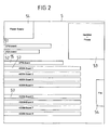
- FIG. 2 shows in detail the structure of a Mobile radio gateways 5.
- the mobile radio gateway has a central processor unit 51, a graphics card 52, hard disk and floppy drives 53, a power supply 54 and a fan 55.
- a 55 insert card three PRI (E1) connections to the fixed network, whereby also a different number of E1 connections can be provided.
- the plug-in card 55 provides a switching matrix, via the incoming connections an output or User channel to be assigned to the mobile network.
- the coupling network is replaced by appropriate software central processor unit 51 provided.
- the mobile radio gateway 5 has a number of Plug-in cards 57 for mobile communications, each one Provide a variety of mobile stations, as shown Embodiment four mobile stations each. According to the prevailing standard in the mobile radio area GSM mobile stations (GSM - Global System for Mobile Communication).
- a plug-in card 57 for the mobile radio is shown in more detail in FIG. 3 shown.
- the plug-in card 57 has on the front and Rear two GSM modules 10a, 10b, the Figure 3 shows only the GSM modules shown on the top 10a, 10b.
- Each GSM module 10a, 10b that only is shown schematically, has the functionality of a Mobile device of a cellular network.
- Each GSM module 10, 10b, several SIM cards are assigned to one only one SIM card is activated at a certain time.
- the SIM cards are on a SIM card slot 11 arranged.
- Form a GSM module 10a, 10b and a SIM card one mobile station each from a cellular network.
- the address of the plug-in card 57 is via a DIP field 12 adjustable.
- a connection to an internal switching matrix of the Gateways 5 take place via a PCM bus 13 or an IOM bus 14.
- An antenna 15 for transmitting or receiving Radio signals are screwed onto the back of the card.
- the plug-in card 57 also preferably has an independent processor 16 with an operating system, which the controls individual modules. Alternatively, control takes place exclusively via the central processor unit.
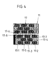
- FIG 4 shows the SIM card slot 11 of Figure 3 in Detail. After that are on the front and back of the Card slots 11 each have space for eight SIM cards 17 provided, so that a total of sixteen SIM cards 17th can be held up.
- Each GSM module 10a, 10b are a maximum of four SIM cards 17 can be assigned. For example are one SIM module 10a four SIM cards 17-1, 17-2, 17-3, 17-4, the GSM module 10b four plug-in cards 17-5, 17-6, 17-7, 17-8, etc. assigned. However, not everyone has to Admission places must be occupied.
- SIM card 17-1 a SIM card of the network D1
- SIM card 17-2 by one SIM card of the network D2
- SIM card 17-3 by one Trade SIM card of the E-Plus network.
- the corresponding SIM card is activated.
- An initial assignment is made.
- the cellular gateway 5 eight mobile radio boards 57, each with four GSM modules on so that there is a maximum of 32 user channels to a cellular network can be provided.
- 32 user channels ten user channels for access to the D1 network, ten user channels for one Access to the D2 network and twelve user channels for access to the E-Plus network are provided. This is achieved in that for ten user channels the SIM card for the network D1, for another ten user channels the SIM cards for the network D2 and SIM cards for the E-Plus network for a further twelve user channels to be activated. Groups of User channels for the network D1, the network D2 and the network E-Plus educated.
- the central processor 51 of the gateway 5 or one other control unit determines that for a particular Mobile network, e.g. the D1 network, the intended user channels are completely or almost completely occupied, for example only a free user channel or another predefinable one Number of free user channels is available, it is checked whether in the other group of user channels for D2 and / or the another group of user channels is still sufficient for E-Plus Cellular channels are available. Sufficient cellular channels are then e.g. available when occupancy is lower is considered the insufficient occupancy of the considered Group. In this case, a user channel is added to the group a low dynamic utilization of the group of user channels switched on for the D1 network, so that this now over eleven Channels.
- a particular Mobile network e.g. the D1 network
- the intended user channels are completely or almost completely occupied, for example only a free user channel or another predefinable one Number of free user channels is available, it is checked whether in the other group of user channels for D2 and / or the another group of user channels
- the SIM card is changed automatically by appropriate programming and dynamic in Dependence on the utilization of the user channels of the individual Mobile networks.
- the available resources on user channels adapt automatically to the current needs on.
- Figure 5a shows a switching matrix 19, the for example in the plug-in card 55 for a PRI (E1) coupling is implemented according to Figure 2.
- the switching network 19 is on the one hand via a PRI connection 18 according to FIG Landline connected.
- the incoming, multiplexed Data channels of the PRI connector 18 are through the Switching network 19 on a large number of individual data channels 20-1, 20-2, 20-3 and 20-4 distributed. This is about the central processor 51 of the gatesway 5 or another Control unit controlled.
- GSM modules 10a, 10b, 10c, 10d each with two SIM cards 17-1, 17-2, 17-3, 17-4, 17-5, 17-6, 17-7, 17-8 and two Cellular networks 7, 8 are provided.
- the data channels 20-1, 20-2, 20-3, 20-4 is controlled by software-controlled switches S. one of the SIM cards 17-1, 17-3, 17-6, 17-8 assigned.
- the switch S is controlled by means of the central one Processor 51 or another control unit.
- Via the GSM modules 10a, 10b, 10c, 10d for each data channel 20-1, 20-2, 20-3, 20-4 each have a useful channel 21, 22, 23, 24, for one Cellular transmission provided.
- the assignment of a User channel 21, 22, 23, 24 to a mobile radio network 17, 18 takes place via the selected SIM card.
- the embodiment 5a are for the two upper useful channels 21, 22 SIM cards 17-1, 17-3 selected, the mobile network 7th assigned.
- the two lower useful channels 23, 24 are the SIM cards 17-6, 17-8 selected, the Mobile network 8 are assigned.
- the other SIM cards 17-2, 17-4, 17-5, 17-7 are not activated.
- the two upper useful channels 21, 22 form a first group a first number N of user channels of the mobile radio network 7, where N is two in the example shown.
- the two lower useful channels 23, 24 form a second group of second number M of user channels of the mobile radio network 8, where M in the example shown is also two.
- the SIM card 17-6 deactivated for network 8 and instead the SIM card 17-5 activated for network 7.
- the control is carried out by the central processor 51 of the gate way 5 or another control unit.
- the useful channel 23 is now also assigned to network 7.
- the number of user channels of the first Group has increased by one, the number of user channels of the second group reduced by one. If the Utilization of the user channels can determine the user channels dynamically changed again.
- the central processor 51 or another Control unit of the mobile radio gateway 5 determines that for the network 7 under consideration is insufficient or insufficient User channels are available, user channels for others Cellular networks 8 are still sufficiently available, however is the number of user channels for at least two groups of user channels redefined and at least one User channel of the group of user channels for the considered Mobile network 7 added. This is done as explained by a change of the SIM card 17 for the considered User channel.
- a mobile radio gateway can have a different number of cell phone plug-in cards, any cell phone plug-in card a different number of GSM modules and each GSM module one have a different number of SIM cards than shown.
- the invention is also not limited to the fact that Gateway an interface between a landline and provides multiple cellular networks. Basically, the described dynamic assignment of user channels also at other communication networks.
Landscapes
- Engineering & Computer Science (AREA)
- Computer Networks & Wireless Communication (AREA)
- Signal Processing (AREA)
- Mobile Radio Communication Systems (AREA)
- Lock And Its Accessories (AREA)
Abstract
Description
- Figur 1 -
- eine Telekommunikationsanordnung mit einem Telekommmunikations-Festnetz und einem daran angeschlossenen Mobilfunk-Gateway;
- Figur 2 -
- schematisch den Aufbau eines Mobilfunk-Gateways gemäß Figur 1;
- Figur 3 -
- schematisch den Aufbau einer Einsteckkarte eines Gateways gemäß Figur 2;
- Figur 4 -
- die Ober- und Unterseite eines SIM-Karteneinschubs einer Einsteckkarte gemäß Figur 3;
- Figur 5a -
- schematisch ein funktionelles Blockschaltbild eines Mobilfunk-Gateways in einem ersten Zuordnungszustand und
- Figur 5b -
- schematisch ein funktionelles Blockschaltbild eines Mobilfunk-Gateways in einem zweiten Zuordnungszustand.
Claims (12)
- Verfahren zur Bereitstellung von Verbindungen zwischen einem rufenden Kommunikationsgerät (1, 1') eines ersten Kommunikationsnetzes (3, 4) und einem gerufenen Kommunikationsgerät (2, 2') eines weiteren Kommunikationsnetzes (7, 8) unter Verwendung eines Gateways (5), das mit dem ersten Kommunikationsnetz (3, 4) verbunden ist, wobeidadurch gekennzeichnet, dassdas Gateway(5)eine erste Gruppe einer ersten Anzahl (N) von Nutzkanälen (21, 22) eines ersten weiteren Kommunikationsnetzes (7) undmindestens eine zweite Gruppe einer zweiten Anzahl (M) von Nutzkanälen (23, 24) eines zweiten weiteren Kommunikationsnetzes (8) verwaltet,zur Herstellung einer Verbindung zwischen dem rufenden Kommunikationsgerät und dem gerufenen Kommunikationsgerät Informationen betreffend einen Verbindungswunsch vom rufenden Kommunikationsgerät (1, 1') zunächst zum Gateway (5) geroutet werden,das Gateway (5) anhand der erhalteten Informationen feststellt, welchem weiteren Kommunikationsnetz (7, 8) das gerufene Kommunikationsgerät (2, 2') zugeordnet ist, unddas Gateway (5) einen Nutzkanal (21-24) des entsprechenden Kommunikationsnetzes (7, 8) für die Verbindung bereitstellt,die Anzahl der Nutzkanäle (21-24) in jeder Gruppe dynamisch festgelegt wird, wobei bei einer Änderung der Festlegung mindestens ein Nutzkanal (23) einer der Gruppen entnommen und einer anderen Gruppe und damit einem anderen Kommunikationsnetz (7, 8) zugeordnet wird,hierzu für jeden Nutzkanal (21-24) eine für ein Kommunikationsnetz (7, 8) spezifische, mit einer Kennung versehene Einsteckkarte (17-1, ..., 17-8) bereitstellt ist, wobei den Nutzkanälen einer Gruppe Einsteckkarten (17-1, 17-3; 17-6, 17-8) desselben Kommunikationsnetzes (7, 8) zugeordnet sind, undeine Änderung der Anzahl der Nutzkanäle in einer Gruppe dadurch erfolgt, dass für einen oder mehrere Nutzkanäle (23) die Einsteckkarte gewechselt und dabei die Einsteckkarte (17-5) eines anderen Kommunikationsnetzes (7) verwendet wird.
- Verfahren nach Anspruch 1, dadurch gekennzeichnet, dass eine Änderung der Festlegung der Anzahl der Nutzkanäle (21-24) in den einzelnen Gruppen automatisch erfolgt, wenn eine vorgebbare Anzahl von freien Nutzkanälen einer Gruppe nicht mehr zur Verfügung steht.
- Verfahren nach Anspruch 2, dadurch gekennzeichnet, dass in jeder Gruppe von Nutzkanälen stets ein freier Nutzkanal bereit gehalten wird.
- Verfahren nach mindestens einem der Anspüche 1 bis 3, dadurch gekennzeichnet, dass die Anzahl der Nutzkanäle in jeder Gruppe erst bei Vorliegen eines Verbindungswunsches neu festgelegt und mindestens ein Nutzkanal neu zugeordnet wird, sofern für die gewünschte Verbindung kein Nutzkanal des dem gerufenen Kommunikationsgerät (2, 2') zugehörigen Kommunikationsnetzes (7, 8) bereitsteht.
- Verfahren nach mindestens einem der Ansprüche 1 bis 4, dadurch gekennzeichnet, dass das erste Kommunikationsnetz ein Telekommunikations-Festnetz (3, 4) und die weiteren Kommunikationsnetze Telekommunikations-Mobilfunknetze (7, 8) sind.
- Verfahren nach mindestens einem der Ansprüche 1 bis 5, dadurch gekennzeichnet, dass ein Wechseln einer Einsteckkarte (23) programmtechnisch realisiert wird, indem für jeden Nutzkanal (21, 22, 23, 24) Einsteckkarten (17-1, ..., 17-8) mindestens zweier Kommunikationsnetze (7, 8) vorgehalten werden und die gewünschte neue Einsteckkarte (17-5) aktiviert, die bisherige Einsteckkarte (17-6) dagegen deaktiviert wird.
- Gateway, das mit einem ersten Kommunikationsnetz (3, 4) verbunden ist und das eine erste Gruppe einer ersten Anzahl (N) von Nutzkanälen (21, 22) eines ersten weiteren Kommunikationsnetzes (7) und mindestens eine zweite Gruppe einer zweiten Anzahl (M) von Nutzkanälen (23, 24) eines zweiten weiteren Kommunikationsnetzes (8) verwaltet, und das aufweist:gekennzeichnet durchMittel (51) zum Auswerten von Informationen betreffend einen Verbindungswunsch eines rufenden Kommunikationsgeräts (1, 1') des ersten Kommunikationsnetzes (3, 4);Mittel (10a-10d) zur Herstellung einer Verbindung zu einem gerufenen Kommunikationsgerät (2, 2') eines der weiteren Kommunikationsnetze (7, 8) und hierzuMittel (16) zum Bereitstellen eines Nutzkanals (21-24) des entsprechenden Kommunikationsnetzes (7, 8) für die gewünschte Verbindung,eine Mehrzahl von mit einer Kennung versehenen Einsteckkarten (17-1, ..., 17-8), wobei jedem Nutzkanal eine für ein Kommunikationsnetz (7, 8) spezifische Einsteckkarte zugeordnet ist und den Nutzkanälen einer Gruppe Einsteckkarten desselben Kommunikationsnetzes (7, 8) zugeordnet sind,Mittel (51), die die Anzahl der Nutzkanäle (21-24) in jeder Gruppe dynamisch festlegen, wobei bei einer Änderung der Festlegung mindestens ein Nutzkanal (23) einer der Gruppen entnommen und einer anderen Gruppe und damit einem anderen Kommunikationsnetz (7, 8) zugeordnet wird, und wobeidie Festlegungsmittel (51) zur Änderung der Anzahl der Nutzkanäle einer Gruppe ein Wechseln der Einsteckkarte für einen oder mehrere Nutzkanäle bewirken, wobei eine gewechselte Einsteckkarte (23) jeweils einem anderen der Kommunikationsnetze (7, 8) zugeordnet ist.
- Gateway nach Anspruch 7, dadurch gekennzeichnet, dass die Festlegungsmittel (51) eine Änderung der Festlegung der Anzahl der Nutzkanäle (21-24) in den einzelnen Gruppen automatisch vornehmen, wenn eine vorgebbare Anzahl von freien Nutzkanälen einer Gruppe nicht mehr zur Verfügung steht.
- Gateway nach Anspruch 8, dadurch gekennzeichnet, dass die Festlegungsmittel (51) in jeder Gruppe von Nutzkanälen stets einen freien Kanal bereit halten.
- Gateway nach mindestens einem der Ansprüche 7 bis 9, dadurch gekennzeichnet, dass die Festlegungsmittel (51) die Anzahl der Nutzkanäle in jeder Gruppe erst bei Vorliegen eines Verbindungswunsches neu festlegen und dabei mindestens einen Nutzkanal neu zuordnen, falls für die gewünschte Verbindung kein Nutzkanal des dem gerufenen Kommunikationsgerät (2, 2') zugehörigen Kommunikationsnetzes (7, 8) bereitsteht.
- Gateway nach mindestens einem der Ansprüche 7 bis 10, dadurch gekennzeichnet, dass das erste Kommunikationsnetz ein Telekommunikations-Festnetz (3, 4) und die weiteren Kommunikationsnetze Telekommunikations-Mobilfunknetze (7, 8) sind.
- Gateway nach mindestens einem der Ansprüche 7 bis 11, dadurch gekennzeichnet, dass dem Gateway (5) für jeden Nutzkanal (21-24) Einsteckkarten (17-1, ..., 17-8) mindestens zweier Kommunikationsnetze (7, 8) zugeordnet sind und die Festlegungsmittel (51) bei einer Änderung der Festlegung für einen betrachteten Nutzkanal (23) programmtechnisch die derzeit aktivierte Einsteckkarte (17-6) deaktivieren und eine andere, dem gewünschten Kommunikationsnetz (7) zugeordnete Einsteckkarte (17-5) aktivieren.
Applications Claiming Priority (2)
| Application Number | Priority Date | Filing Date | Title |
|---|---|---|---|
| DE10260401A DE10260401B4 (de) | 2002-12-16 | 2002-12-16 | Verfahren und Gateway zur Bereitstellung von Verbindungen, insbesondere zwischen einem Telekommunikations-Festnetz und einem Telekommunikations-Mobilfunknetz |
| DE10260401 | 2002-12-16 |
Publications (2)
| Publication Number | Publication Date |
|---|---|
| EP1432257A1 true EP1432257A1 (de) | 2004-06-23 |
| EP1432257B1 EP1432257B1 (de) | 2005-07-27 |
Family
ID=32336556
Family Applications (1)
| Application Number | Title | Priority Date | Filing Date |
|---|---|---|---|
| EP03090407A Expired - Lifetime EP1432257B1 (de) | 2002-12-16 | 2003-11-26 | Verfahren und Gateway zur Bereitstellung von Verbindungen, insbesondere zwischen einem Telekommunikations-Festnetz und einem Telekommunikations-Mobilfunknetz |
Country Status (6)
| Country | Link |
|---|---|
| EP (1) | EP1432257B1 (de) |
| AT (1) | ATE300841T1 (de) |
| AU (1) | AU2003268879A1 (de) |
| DE (2) | DE10260401B4 (de) |
| ES (1) | ES2246456T3 (de) |
| PT (1) | PT1432257E (de) |
Cited By (6)
| Publication number | Priority date | Publication date | Assignee | Title |
|---|---|---|---|---|
| WO2006045706A1 (en) * | 2004-10-27 | 2006-05-04 | Telefonaktiebolaget Lm Ericsson (Publ) | Ip multimedia subsystem access method and apparatus |
| WO2006054980A1 (en) * | 2004-11-15 | 2006-05-26 | Cingular Wireless Ii, Llc | Programming and/or activating of a subscriber identity module (sim) for an analog telephone adapter (ata) device |
| WO2007002725A1 (en) * | 2005-06-28 | 2007-01-04 | Mavenir Systems, Inc. | System and method for switching peer-to-peer multimedia in an enterprise network |
| WO2007069942A1 (en) | 2005-12-13 | 2007-06-21 | Telefonaktiebolaget Lm Ericsson (Publ) | A method and arrangement for enabling multimedia communication. |
| US7623852B2 (en) | 2004-11-15 | 2009-11-24 | At&T Mobility Ii Llc | Remote programming/activation of SIM enabled ATA device |
| DE102008035033A1 (de) | 2008-07-24 | 2010-01-28 | Teles Ag Informationstechnologien | Verfahren zum Nutzen von Sprachansagen in Telekommunikationsverbindungen |
Families Citing this family (3)
| Publication number | Priority date | Publication date | Assignee | Title |
|---|---|---|---|---|
| DE102004048345B4 (de) | 2004-10-01 | 2006-10-05 | Teles Ag Informationstechnologien | Verfahren zum Bereitstellen von ein Mobilfunkgerät in einem Mobilfunknetzwerk identifzierenden Geräteidentifikationen in dem Mobilfunkgerät |
| DE102005056623A1 (de) * | 2005-11-25 | 2007-05-31 | Deutsche Telekom Ag | Mobile Vermittlungsvorrichtung und Verfahren zum Übertragen von Informationen zwischen wenigstens zwei Teilnehmern |
| DE102007062696A1 (de) * | 2007-12-27 | 2009-07-02 | Extcel Communications Gmbh | Verfahren für die Übertragung von a-Nummern für Kommunikationen in Mobilfunknetze über spezifische Gateways |
Citations (3)
| Publication number | Priority date | Publication date | Assignee | Title |
|---|---|---|---|---|
| EP0844797A2 (de) * | 1996-11-20 | 1998-05-27 | Lucent Technologies Inc. | Verfahren zur allgegenwärtigen Dienstbereitstellung an einem mobilen Teilnehmern dass einen schnurlosen Übergangsschalter verwendet |
| US6374112B1 (en) * | 1998-04-03 | 2002-04-16 | Telefonaktiebolaget Lm Ericsson (Publ) | Flexible radio access and resource allocation in a universal mobile telephone system |
| US20030081565A1 (en) * | 2001-11-01 | 2003-05-01 | Mcintosh Chris P. | Method and apparatus for providing communication between a PBX terminal and a public wireless network via a private wireless network |
Family Cites Families (4)
| Publication number | Priority date | Publication date | Assignee | Title |
|---|---|---|---|---|
| SE467559B (sv) * | 1991-04-12 | 1992-08-03 | Comvik Gsm Ab | Foerfarande vid telefonsystem |
| DE19800967C2 (de) * | 1998-01-14 | 2000-11-09 | Deutsche Telekom Ag | Vorrichtung zum stationären Betreiben von Mobilfunkgeräten |
| DE10002027A1 (de) * | 2000-01-19 | 2001-07-26 | Tenovis Gmbh & Co Kg | Vorrichtung zur direkten Herstellung von Telekommunikationsverbindungen von einer TK-Anlage ins Mobilfunknetz |
| DE20014342U1 (de) * | 2000-08-17 | 2000-11-16 | Bäumler, Manfred, 95704 Pullenreuth | Mobilfunktelekommunikationsgerät (Handy) mit wenigstens zwei SIM-Karten-Lesevorrichtungen |
-
2002
- 2002-12-16 DE DE10260401A patent/DE10260401B4/de not_active Expired - Fee Related
-
2003
- 2003-11-26 AT AT03090407T patent/ATE300841T1/de not_active IP Right Cessation
- 2003-11-26 ES ES03090407T patent/ES2246456T3/es not_active Expired - Lifetime
- 2003-11-26 EP EP03090407A patent/EP1432257B1/de not_active Expired - Lifetime
- 2003-11-26 DE DE50300852T patent/DE50300852D1/de not_active Expired - Lifetime
- 2003-11-26 PT PT03090407T patent/PT1432257E/pt unknown
- 2003-12-16 AU AU2003268879A patent/AU2003268879A1/en not_active Abandoned
Patent Citations (3)
| Publication number | Priority date | Publication date | Assignee | Title |
|---|---|---|---|---|
| EP0844797A2 (de) * | 1996-11-20 | 1998-05-27 | Lucent Technologies Inc. | Verfahren zur allgegenwärtigen Dienstbereitstellung an einem mobilen Teilnehmern dass einen schnurlosen Übergangsschalter verwendet |
| US6374112B1 (en) * | 1998-04-03 | 2002-04-16 | Telefonaktiebolaget Lm Ericsson (Publ) | Flexible radio access and resource allocation in a universal mobile telephone system |
| US20030081565A1 (en) * | 2001-11-01 | 2003-05-01 | Mcintosh Chris P. | Method and apparatus for providing communication between a PBX terminal and a public wireless network via a private wireless network |
Cited By (12)
| Publication number | Priority date | Publication date | Assignee | Title |
|---|---|---|---|---|
| WO2006045706A1 (en) * | 2004-10-27 | 2006-05-04 | Telefonaktiebolaget Lm Ericsson (Publ) | Ip multimedia subsystem access method and apparatus |
| KR101018589B1 (ko) * | 2004-10-27 | 2011-03-03 | 텔레호낙티에볼라게트 엘엠 에릭슨(피유비엘) | Ip 멀티미디어 서브시스템 액세스 방법 및 장치 |
| RU2418389C2 (ru) * | 2004-10-27 | 2011-05-10 | Телефонактиеболагет Лм Эрикссон (Пабл) | Способ и устройство доступа к подсистеме ip-мультимедиа |
| US8160578B2 (en) | 2004-10-27 | 2012-04-17 | Telefonaktiebolaget Lm Ericsson (Publ) | IP multimedia subsystem access method and apparatus |
| JP4938674B2 (ja) * | 2004-10-27 | 2012-05-23 | テレフオンアクチーボラゲット エル エム エリクソン(パブル) | Ipマルチメディア・サブシステムにアクセスする方法および装置 |
| WO2006054980A1 (en) * | 2004-11-15 | 2006-05-26 | Cingular Wireless Ii, Llc | Programming and/or activating of a subscriber identity module (sim) for an analog telephone adapter (ata) device |
| US7623852B2 (en) | 2004-11-15 | 2009-11-24 | At&T Mobility Ii Llc | Remote programming/activation of SIM enabled ATA device |
| US8380180B2 (en) | 2004-11-15 | 2013-02-19 | At&T Mobility Ii Llc | Remote programming/activation of SIM enabled ATA device |
| WO2007002725A1 (en) * | 2005-06-28 | 2007-01-04 | Mavenir Systems, Inc. | System and method for switching peer-to-peer multimedia in an enterprise network |
| WO2007069942A1 (en) | 2005-12-13 | 2007-06-21 | Telefonaktiebolaget Lm Ericsson (Publ) | A method and arrangement for enabling multimedia communication. |
| DE102008035033A1 (de) | 2008-07-24 | 2010-01-28 | Teles Ag Informationstechnologien | Verfahren zum Nutzen von Sprachansagen in Telekommunikationsverbindungen |
| US8605737B2 (en) | 2008-07-24 | 2013-12-10 | Teles Ag Informationstechnologien | Method for using voice messages in telecommunications connections |
Also Published As
| Publication number | Publication date |
|---|---|
| AU2003268879A1 (en) | 2004-07-01 |
| DE10260401B4 (de) | 2007-05-24 |
| ES2246456T3 (es) | 2006-02-16 |
| ATE300841T1 (de) | 2005-08-15 |
| PT1432257E (pt) | 2005-11-30 |
| DE10260401A1 (de) | 2004-07-15 |
| EP1432257B1 (de) | 2005-07-27 |
| DE50300852D1 (de) | 2005-09-01 |
Similar Documents
| Publication | Publication Date | Title |
|---|---|---|
| EP1566069B1 (de) | Testsystem zur prüfung von übertragungsvorgängen innerhalb eines mobilfunknetzes sowie verfahren zur authentisierung eines mobiltelefons unter verwendung eines derartigen testsystems | |
| EP2104394B1 (de) | Verfahren und Telekommunikationsanordnung zum Bereitstellen einer Telekommunikationsverbindung (TK-Verbindung) zu einem gerufenen Mobilfunkendgerät | |
| DE10311980A1 (de) | Verfahren zum Bereitstellen von mit einer Kennung versehenen Einsteckkarten in einem Mobilfunkendgerät | |
| EP0773693A2 (de) | Netzanpassungszentrale für ein Mobilfunknetz | |
| EP1432257B1 (de) | Verfahren und Gateway zur Bereitstellung von Verbindungen, insbesondere zwischen einem Telekommunikations-Festnetz und einem Telekommunikations-Mobilfunknetz | |
| EP1606964B1 (de) | Gebührenabhängiges aktivieren und deaktivieren von sim-karten in einem mobilfunk-gateway oder mobilfunkendgerät und verfahren dafür | |
| WO1996017483A1 (de) | Funksystem für eine geschlossene benutzergruppe | |
| DE19702868C1 (de) | Verfahren zur Übertragung von Informationen zwischen Mobilstationen und einem Kommunikationsnetz | |
| EP1357732B1 (de) | Server für ein Telekommunikationssystem und Verfahren zum Erstellen einer Telekommunikationsverbindung | |
| EP0868823A2 (de) | Verfahren zur übertragung in einem universellen übertragungsnetz | |
| EP2700281B1 (de) | Verfahren zum leiten von telekommunikationsverbindungen zu einem mobilfunk-endgerät sowie mobilfunk-gateway | |
| DE4143266C1 (de) | ||
| EP1595407B1 (de) | Verfahren und telekommunikationsendgerät zur bereitstellung einer telekommunikationsverbindung zwischen zwei endgeräten | |
| DE4141725C2 (de) | Schaltungsanordnung zum Übertragen nachrichtentechnischer Signale | |
| EP2689596B1 (de) | Verfahren und vorrichtungen zum leiten von telekommunikationsverbindungen (tk-verbindungen) zu einem mobilfunk-endgerät | |
| EP2220860B1 (de) | Verfahren zum nutzen von sprachansagen in telekommunikationsverbindungen | |
| DE19917062C2 (de) | Optimierte Schnittstelle zwischen Zugriffsnetzwerk und Vermittlungseinrichtung | |
| DE4411119C1 (de) | Digitales, in Funkzellen aufgebautes Mobilfunksystem | |
| EP1749398B1 (de) | Bereitstellung einer telekommunikationsverbindung zwischen zwei endgeräten mit ermittlung des telkommunikationsnetzes des gerufenen teilnehmers | |
| DE10034938A1 (de) | Mobilfunksystem und Verfahren zur Realisierung eines Mobilfunknetzes unter Verwendung dieses Mobilfunksystems |
Legal Events
| Date | Code | Title | Description |
|---|---|---|---|
| PUAI | Public reference made under article 153(3) epc to a published international application that has entered the european phase |
Free format text: ORIGINAL CODE: 0009012 |
|
| AK | Designated contracting states |
Kind code of ref document: A1 Designated state(s): AT BE BG CH CY CZ DE DK EE ES FI FR GB GR HU IE IT LI LU MC NL PT RO SE SI SK TR |
|
| AX | Request for extension of the european patent |
Extension state: AL LT LV MK |
|
| 17P | Request for examination filed |
Effective date: 20041103 |
|
| GRAP | Despatch of communication of intention to grant a patent |
Free format text: ORIGINAL CODE: EPIDOSNIGR1 |
|
| AKX | Designation fees paid |
Designated state(s): AT BE BG CH CY CZ DE DK EE ES FI FR GB GR HU IE IT LI LU MC NL PT RO SE SI SK TR |
|
| GRAS | Grant fee paid |
Free format text: ORIGINAL CODE: EPIDOSNIGR3 |
|
| GRAA | (expected) grant |
Free format text: ORIGINAL CODE: 0009210 |
|
| AK | Designated contracting states |
Kind code of ref document: B1 Designated state(s): AT BE BG CH CY CZ DE DK EE ES FI FR GB GR HU IE IT LI LU MC NL PT RO SE SI SK TR |
|
| PG25 | Lapsed in a contracting state [announced via postgrant information from national office to epo] |
Ref country code: SK Free format text: LAPSE BECAUSE OF FAILURE TO SUBMIT A TRANSLATION OF THE DESCRIPTION OR TO PAY THE FEE WITHIN THE PRESCRIBED TIME-LIMIT Effective date: 20050727 Ref country code: FI Free format text: LAPSE BECAUSE OF FAILURE TO SUBMIT A TRANSLATION OF THE DESCRIPTION OR TO PAY THE FEE WITHIN THE PRESCRIBED TIME-LIMIT Effective date: 20050727 Ref country code: SI Free format text: LAPSE BECAUSE OF FAILURE TO SUBMIT A TRANSLATION OF THE DESCRIPTION OR TO PAY THE FEE WITHIN THE PRESCRIBED TIME-LIMIT Effective date: 20050727 Ref country code: CZ Free format text: LAPSE BECAUSE OF FAILURE TO SUBMIT A TRANSLATION OF THE DESCRIPTION OR TO PAY THE FEE WITHIN THE PRESCRIBED TIME-LIMIT Effective date: 20050727 Ref country code: EE Free format text: LAPSE BECAUSE OF FAILURE TO SUBMIT A TRANSLATION OF THE DESCRIPTION OR TO PAY THE FEE WITHIN THE PRESCRIBED TIME-LIMIT Effective date: 20050727 Ref country code: RO Free format text: LAPSE BECAUSE OF FAILURE TO SUBMIT A TRANSLATION OF THE DESCRIPTION OR TO PAY THE FEE WITHIN THE PRESCRIBED TIME-LIMIT Effective date: 20050727 Ref country code: IE Free format text: LAPSE BECAUSE OF FAILURE TO SUBMIT A TRANSLATION OF THE DESCRIPTION OR TO PAY THE FEE WITHIN THE PRESCRIBED TIME-LIMIT Effective date: 20050727 |
|
| REG | Reference to a national code |
Ref country code: GB Ref legal event code: FG4D Free format text: NOT ENGLISH |
|
| REG | Reference to a national code |
Ref country code: CH Ref legal event code: EP |
|
| REG | Reference to a national code |
Ref country code: IE Ref legal event code: FG4D Free format text: LANGUAGE OF EP DOCUMENT: GERMAN |
|
| REF | Corresponds to: |
Ref document number: 50300852 Country of ref document: DE Date of ref document: 20050901 Kind code of ref document: P |
|
| GBT | Gb: translation of ep patent filed (gb section 77(6)(a)/1977) |
Effective date: 20050917 |
|
| PG25 | Lapsed in a contracting state [announced via postgrant information from national office to epo] |
Ref country code: SE Free format text: LAPSE BECAUSE OF FAILURE TO SUBMIT A TRANSLATION OF THE DESCRIPTION OR TO PAY THE FEE WITHIN THE PRESCRIBED TIME-LIMIT Effective date: 20051027 Ref country code: BG Free format text: LAPSE BECAUSE OF FAILURE TO SUBMIT A TRANSLATION OF THE DESCRIPTION OR TO PAY THE FEE WITHIN THE PRESCRIBED TIME-LIMIT Effective date: 20051027 Ref country code: DK Free format text: LAPSE BECAUSE OF FAILURE TO SUBMIT A TRANSLATION OF THE DESCRIPTION OR TO PAY THE FEE WITHIN THE PRESCRIBED TIME-LIMIT Effective date: 20051027 |
|
| PG25 | Lapsed in a contracting state [announced via postgrant information from national office to epo] |
Ref country code: CY Free format text: LAPSE BECAUSE OF FAILURE TO SUBMIT A TRANSLATION OF THE DESCRIPTION OR TO PAY THE FEE WITHIN THE PRESCRIBED TIME-LIMIT Effective date: 20051126 Ref country code: AT Free format text: LAPSE BECAUSE OF NON-PAYMENT OF DUE FEES Effective date: 20051126 |
|
| PG25 | Lapsed in a contracting state [announced via postgrant information from national office to epo] |
Ref country code: MC Free format text: LAPSE BECAUSE OF NON-PAYMENT OF DUE FEES Effective date: 20051130 Ref country code: LU Free format text: LAPSE BECAUSE OF NON-PAYMENT OF DUE FEES Effective date: 20051130 |
|
| REG | Reference to a national code |
Ref country code: GR Ref legal event code: EP Ref document number: 20050403067 Country of ref document: GR |
|
| PG25 | Lapsed in a contracting state [announced via postgrant information from national office to epo] |
Ref country code: HU Free format text: LAPSE BECAUSE OF FAILURE TO SUBMIT A TRANSLATION OF THE DESCRIPTION OR TO PAY THE FEE WITHIN THE PRESCRIBED TIME-LIMIT Effective date: 20060128 |
|
| REG | Reference to a national code |
Ref country code: ES Ref legal event code: FG2A Ref document number: 2246456 Country of ref document: ES Kind code of ref document: T3 |
|
| REG | Reference to a national code |
Ref country code: IE Ref legal event code: FD4D |
|
| ET | Fr: translation filed | ||
| PLBE | No opposition filed within time limit |
Free format text: ORIGINAL CODE: 0009261 |
|
| STAA | Information on the status of an ep patent application or granted ep patent |
Free format text: STATUS: NO OPPOSITION FILED WITHIN TIME LIMIT |
|
| 26N | No opposition filed |
Effective date: 20060428 |
|
| PG25 | Lapsed in a contracting state [announced via postgrant information from national office to epo] |
Ref country code: CH Free format text: LAPSE BECAUSE OF NON-PAYMENT OF DUE FEES Effective date: 20071130 Ref country code: LI Free format text: LAPSE BECAUSE OF NON-PAYMENT OF DUE FEES Effective date: 20071130 |
|
| REG | Reference to a national code |
Ref country code: CH Ref legal event code: PL |
|
| PGFP | Annual fee paid to national office [announced via postgrant information from national office to epo] |
Ref country code: TR Payment date: 20141120 Year of fee payment: 12 Ref country code: GR Payment date: 20141120 Year of fee payment: 12 |
|
| PGFP | Annual fee paid to national office [announced via postgrant information from national office to epo] |
Ref country code: PT Payment date: 20141124 Year of fee payment: 12 Ref country code: NL Payment date: 20141120 Year of fee payment: 12 |
|
| PGFP | Annual fee paid to national office [announced via postgrant information from national office to epo] |
Ref country code: BE Payment date: 20141125 Year of fee payment: 12 |
|
| REG | Reference to a national code |
Ref country code: FR Ref legal event code: PLFP Year of fee payment: 13 |
|
| PGFP | Annual fee paid to national office [announced via postgrant information from national office to epo] |
Ref country code: IT Payment date: 20151124 Year of fee payment: 13 Ref country code: GB Payment date: 20151123 Year of fee payment: 13 Ref country code: DE Payment date: 20151119 Year of fee payment: 13 |
|
| PGFP | Annual fee paid to national office [announced via postgrant information from national office to epo] |
Ref country code: ES Payment date: 20151124 Year of fee payment: 13 Ref country code: FR Payment date: 20151124 Year of fee payment: 13 |
|
| REG | Reference to a national code |
Ref country code: PT Ref legal event code: MM4A Free format text: LAPSE DUE TO NON-PAYMENT OF FEES Effective date: 20160527 |
|
| PG25 | Lapsed in a contracting state [announced via postgrant information from national office to epo] |
Ref country code: GR Free format text: LAPSE BECAUSE OF NON-PAYMENT OF DUE FEES Effective date: 20160602 |
|
| REG | Reference to a national code |
Ref country code: NL Ref legal event code: MM Effective date: 20151201 |
|
| PG25 | Lapsed in a contracting state [announced via postgrant information from national office to epo] |
Ref country code: PT Free format text: LAPSE BECAUSE OF NON-PAYMENT OF DUE FEES Effective date: 20160527 |
|
| PG25 | Lapsed in a contracting state [announced via postgrant information from national office to epo] |
Ref country code: NL Free format text: LAPSE BECAUSE OF NON-PAYMENT OF DUE FEES Effective date: 20151201 |
|
| REG | Reference to a national code |
Ref country code: GR Ref legal event code: ML Ref document number: 20050403067 Country of ref document: GR Effective date: 20160602 |
|
| REG | Reference to a national code |
Ref country code: DE Ref legal event code: R119 Ref document number: 50300852 Country of ref document: DE |
|
| GBPC | Gb: european patent ceased through non-payment of renewal fee |
Effective date: 20161126 |
|
| PG25 | Lapsed in a contracting state [announced via postgrant information from national office to epo] |
Ref country code: BE Free format text: LAPSE BECAUSE OF NON-PAYMENT OF DUE FEES Effective date: 20151130 |
|
| REG | Reference to a national code |
Ref country code: FR Ref legal event code: ST Effective date: 20170731 |
|
| PG25 | Lapsed in a contracting state [announced via postgrant information from national office to epo] |
Ref country code: TR Free format text: LAPSE BECAUSE OF NON-PAYMENT OF DUE FEES Effective date: 20151126 |
|
| PG25 | Lapsed in a contracting state [announced via postgrant information from national office to epo] |
Ref country code: IT Free format text: LAPSE BECAUSE OF NON-PAYMENT OF DUE FEES Effective date: 20161126 Ref country code: FR Free format text: LAPSE BECAUSE OF NON-PAYMENT OF DUE FEES Effective date: 20161130 |
|
| PG25 | Lapsed in a contracting state [announced via postgrant information from national office to epo] |
Ref country code: DE Free format text: LAPSE BECAUSE OF NON-PAYMENT OF DUE FEES Effective date: 20170601 Ref country code: GB Free format text: LAPSE BECAUSE OF NON-PAYMENT OF DUE FEES Effective date: 20161126 |
|
| PG25 | Lapsed in a contracting state [announced via postgrant information from national office to epo] |
Ref country code: ES Free format text: LAPSE BECAUSE OF NON-PAYMENT OF DUE FEES Effective date: 20161127 |
|
| REG | Reference to a national code |
Ref country code: ES Ref legal event code: FD2A Effective date: 20181120 |