EP1432563B1 - Verfahren und vorrichtung zur bereitstellung von druckbeaufschlagter abgasluft an mehreren verwendungspunkten in einer blasformvorrichtung - Google Patents
Verfahren und vorrichtung zur bereitstellung von druckbeaufschlagter abgasluft an mehreren verwendungspunkten in einer blasformvorrichtung Download PDFInfo
- Publication number
- EP1432563B1 EP1432563B1 EP02800188A EP02800188A EP1432563B1 EP 1432563 B1 EP1432563 B1 EP 1432563B1 EP 02800188 A EP02800188 A EP 02800188A EP 02800188 A EP02800188 A EP 02800188A EP 1432563 B1 EP1432563 B1 EP 1432563B1
- Authority
- EP
- European Patent Office
- Prior art keywords
- compressed air
- valves
- points
- blow
- control valve
- Prior art date
- Legal status (The legal status is an assumption and is not a legal conclusion. Google has not performed a legal analysis and makes no representation as to the accuracy of the status listed.)
- Expired - Lifetime
Links
- 238000000071 blow moulding Methods 0.000 title claims abstract description 84
- 238000000034 method Methods 0.000 title claims description 26
- 230000000694 effects Effects 0.000 claims abstract description 14
- 230000009467 reduction Effects 0.000 claims description 3
- 239000000463 material Substances 0.000 description 10
- 230000008569 process Effects 0.000 description 7
- 229920003023 plastic Polymers 0.000 description 6
- 239000004033 plastic Substances 0.000 description 6
- 239000012768 molten material Substances 0.000 description 4
- 238000010586 diagram Methods 0.000 description 3
- 229920000573 polyethylene Polymers 0.000 description 3
- 238000007664 blowing Methods 0.000 description 2
- 235000013305 food Nutrition 0.000 description 2
- 239000011521 glass Substances 0.000 description 2
- 229910000906 Bronze Inorganic materials 0.000 description 1
- XAGFODPZIPBFFR-UHFFFAOYSA-N aluminium Chemical compound [Al] XAGFODPZIPBFFR-UHFFFAOYSA-N 0.000 description 1
- 229910052782 aluminium Inorganic materials 0.000 description 1
- 230000008901 benefit Effects 0.000 description 1
- 235000013361 beverage Nutrition 0.000 description 1
- 239000010974 bronze Substances 0.000 description 1
- 230000000052 comparative effect Effects 0.000 description 1
- 238000001816 cooling Methods 0.000 description 1
- KUNSUQLRTQLHQQ-UHFFFAOYSA-N copper tin Chemical compound [Cu].[Sn] KUNSUQLRTQLHQQ-UHFFFAOYSA-N 0.000 description 1
- 230000036541 health Effects 0.000 description 1
- 238000004519 manufacturing process Methods 0.000 description 1
- 239000008267 milk Substances 0.000 description 1
- 210000004080 milk Anatomy 0.000 description 1
- 235000013336 milk Nutrition 0.000 description 1
- 239000002991 molded plastic Substances 0.000 description 1
- 230000003584 silencer Effects 0.000 description 1
- 229910001220 stainless steel Inorganic materials 0.000 description 1
- 239000010935 stainless steel Substances 0.000 description 1
Images







Classifications
-
- B—PERFORMING OPERATIONS; TRANSPORTING
- B29—WORKING OF PLASTICS; WORKING OF SUBSTANCES IN A PLASTIC STATE IN GENERAL
- B29C—SHAPING OR JOINING OF PLASTICS; SHAPING OF MATERIAL IN A PLASTIC STATE, NOT OTHERWISE PROVIDED FOR; AFTER-TREATMENT OF THE SHAPED PRODUCTS, e.g. REPAIRING
- B29C49/00—Blow-moulding, i.e. blowing a preform or parison to a desired shape within a mould; Apparatus therefor
- B29C49/42—Component parts, details or accessories; Auxiliary operations
- B29C49/78—Measuring, controlling or regulating
- B29C49/783—Measuring, controlling or regulating blowing pressure
-
- B—PERFORMING OPERATIONS; TRANSPORTING
- B29—WORKING OF PLASTICS; WORKING OF SUBSTANCES IN A PLASTIC STATE IN GENERAL
- B29C—SHAPING OR JOINING OF PLASTICS; SHAPING OF MATERIAL IN A PLASTIC STATE, NOT OTHERWISE PROVIDED FOR; AFTER-TREATMENT OF THE SHAPED PRODUCTS, e.g. REPAIRING
- B29C49/00—Blow-moulding, i.e. blowing a preform or parison to a desired shape within a mould; Apparatus therefor
- B29C49/42—Component parts, details or accessories; Auxiliary operations
- B29C49/58—Blowing means
-
- B—PERFORMING OPERATIONS; TRANSPORTING
- B29—WORKING OF PLASTICS; WORKING OF SUBSTANCES IN A PLASTIC STATE IN GENERAL
- B29C—SHAPING OR JOINING OF PLASTICS; SHAPING OF MATERIAL IN A PLASTIC STATE, NOT OTHERWISE PROVIDED FOR; AFTER-TREATMENT OF THE SHAPED PRODUCTS, e.g. REPAIRING
- B29C49/00—Blow-moulding, i.e. blowing a preform or parison to a desired shape within a mould; Apparatus therefor
- B29C49/42—Component parts, details or accessories; Auxiliary operations
- B29C49/62—Venting means
- B29C2049/6271—Venting means for venting blowing medium, e.g. using damper or silencer
-
- B—PERFORMING OPERATIONS; TRANSPORTING
- B29—WORKING OF PLASTICS; WORKING OF SUBSTANCES IN A PLASTIC STATE IN GENERAL
- B29C—SHAPING OR JOINING OF PLASTICS; SHAPING OF MATERIAL IN A PLASTIC STATE, NOT OTHERWISE PROVIDED FOR; AFTER-TREATMENT OF THE SHAPED PRODUCTS, e.g. REPAIRING
- B29C49/00—Blow-moulding, i.e. blowing a preform or parison to a desired shape within a mould; Apparatus therefor
- B29C49/42—Component parts, details or accessories; Auxiliary operations
- B29C49/78—Measuring, controlling or regulating
- B29C49/783—Measuring, controlling or regulating blowing pressure
- B29C2049/7831—Measuring, controlling or regulating blowing pressure characterised by pressure values or ranges
-
- B—PERFORMING OPERATIONS; TRANSPORTING
- B29—WORKING OF PLASTICS; WORKING OF SUBSTANCES IN A PLASTIC STATE IN GENERAL
- B29C—SHAPING OR JOINING OF PLASTICS; SHAPING OF MATERIAL IN A PLASTIC STATE, NOT OTHERWISE PROVIDED FOR; AFTER-TREATMENT OF THE SHAPED PRODUCTS, e.g. REPAIRING
- B29C49/00—Blow-moulding, i.e. blowing a preform or parison to a desired shape within a mould; Apparatus therefor
- B29C49/42—Component parts, details or accessories; Auxiliary operations
- B29C49/78—Measuring, controlling or regulating
- B29C49/783—Measuring, controlling or regulating blowing pressure
- B29C2049/7832—Blowing with two or more pressure levels
-
- B—PERFORMING OPERATIONS; TRANSPORTING
- B29—WORKING OF PLASTICS; WORKING OF SUBSTANCES IN A PLASTIC STATE IN GENERAL
- B29L—INDEXING SCHEME ASSOCIATED WITH SUBCLASS B29C, RELATING TO PARTICULAR ARTICLES
- B29L2031/00—Other particular articles
- B29L2031/712—Containers; Packaging elements or accessories, Packages
-
- B—PERFORMING OPERATIONS; TRANSPORTING
- B29—WORKING OF PLASTICS; WORKING OF SUBSTANCES IN A PLASTIC STATE IN GENERAL
- B29L—INDEXING SCHEME ASSOCIATED WITH SUBCLASS B29C, RELATING TO PARTICULAR ARTICLES
- B29L2031/00—Other particular articles
- B29L2031/712—Containers; Packaging elements or accessories, Packages
- B29L2031/7158—Bottles
Definitions
- the present invention relates to an apparatus and a method for blow moulding materials at a plurality of points of use using compressed air.
- the process of blow moulding utilizes a compressed air source 100 being connected to a compressed air manifold 101, being operable to transport the compressed air to the point of use 102 within a mould 103.
- a compressed air manifold 101 being operable to transport the compressed air to the point of use 102 within a mould 103.
- the molten plastic is first dripped onto a needle 104 from where the compressed air emerges. Air is forced into the molten plastic which expands up to the extremity within the mould, thereby forming the receptacle.
- EP-A-0 919 355 discloses such a process.
- FIG. 2 A feature common to all prior art blow moulding apparatus is the utilization and positioning of an exhaust valve 201 within the blow moulding apparatus.
- a typical prior art blow moulding device comprises an exhaust 201 being connected directly to the manifold 101 via a suitable valve 202.
- the inventors through familiarization with the blow moulding apparatus and method, have realized various problems and disadvantages with the employment of an exhaust valve connected directly to the manifold.
- the identified problems include:
- blow moulding apparatus and method that utilizes a plurality of exhaust points being positioned at each point of use (in close proximity to the mould), such that a blow moulding device is configured to exhaust compressed air from within the mould cavity only without resort to the unnecessary exhausting of large volumes of compressed air within the manifold.
- compressed air consumption for any given blow moulding cycle may be reduced in addition to a reduction in the cycle time as a result of the capability to exhaust at the points of use, whereby a comparatively small volume of compressed air is exhausted.
- An improved blow moulding device is described herein below.
- a blow moulding device capable of reduced compressed air consumption and cycle time, with respect to those found in the art.
- a blow moulding device is provided with a plurality of exhaust points positioned in close proximity to a plurality of points of use, such that, following the deforming or blowing of material at the plurality of points of using the compressed air, only compressed air contained within each mould cavity is exhausted in contrast to the exhausting system as found in the art.
- the inventors through a series of comparative testing, have found improvements in compressed air consumption over blow moulding devices utilizing a single exhaust point of approximately 33% per pint of blow moulded plastic. Moreover, the inventors have realized a reduction in the cycle time of approximately 0.4 seconds for a device having 8 points of use. This represents a considerable saving given the large number of blow moulding cycles repeated in any one manufacturing day.
- the inventors provide a blow moulding device being operable to blow mold material at the high compressed air pressure range 2.5 x 10 6 Pa to 4.5 x 10 6 Pa.
- the inventors provide a blow moulding device capable of blow moulding a material using compressed air at a relatively low pressure of 5.5 x 10 5 Pa and, according to a third specific implementation of the present invention the inventors provide a blow moulding device capable of blow moulding a material with compressed air at two substantially different pressure ranges or values these being, blow moulding at a first pressure range of 1 x 10 5 Pa to 5 x 10 5 Pa, and at a second pressure of approximately 5.5 x 10 5 Pa. All three specific implementations utilizing a plurality of exhaust points positioned in close proximity to the plurality of points of use, thereby negating the requirement for the exhausting of compressed air from within a single manifold or multiple manifolds.
- blow moulding apparatus configured to reduce a blow moulding cycle time, said apparatus comprising:
- a method of blow moulding configured to reduce a blow moulding cycle time, said method comprising:
- a blow moulding device having a plurality of exhaust points positioned in close proximity to a plurality of points of use according to one embodiment of the present invention.
- the device comprises a single manifold 101 into which compressed air, from a compressed air source, is supplied. Connected directly to the manifold are a plurality of points of use 102 positioned within a plurality of moulds 103. Compressed air is provided to the moulds via valves 200, such that following the forming of a receptacle, (e.g. plastic material), through the blowing of compressed air into the mould cavity, compressed air from within the cavity is exhausted via the plurality of exhaust valves 300. Through the utilization of a plurality of exhaust valves 300 and the plurality of valves 200 compressed air within the manifold 101 is not exhausted.
- a receptacle e.g. plastic material
- the device according to the specific implementation comprises the plurality of moulds 103 within which are positioned a plurality of points of use 102 being connected to a plurality of valves 200.
- the plurality of valves 200 are connected to a plurality of exhaust valves 300 so as to provide a plurality of exhaust points being located in close proximity to the plurality of points of use.
- the points of use 102 are connected to a first manifold or initial blow manifold 400 being supplied with compressed air 401 of relatively low pressure (5.5 x 10 5 Pa). Additionally, the plurality of points of use are connected to a second or main blow manifold 402, being supplied with compressed air at a relatively high pressure, being within the range 2.5 x 10 6 Pa to 4.5 x 10 6 Pa.
- exhaust valves 300 are configured with silencers such that the exhausting of gas from within the mould cavities 102 does not give rise to excessive noise thereby avoiding violation of any health and safety legislation.
- compressed air from the first compressed air source 401 is provided to the points of use 102 via the initial blow manifold 400.
- the second compressed air source 403 then provides compressed air to the main blow manifold 402 and to the points of use thereby providing a main blow to the receptacle.
- the initial blow of compressed air into the molten material to form the receptacle is sufficient to propel the molten material up to a region in close proximity to the inner walls of moulds 103.
- the main blow thereafter, and being at higher pressure, forces the material against the inner wall of moulds 103 so as to generate perfect or near perfect receptacles having outer dimensions corresponding to the inner walls of the plurality of moulds 103.
- the device is configured for exhausting compressed air from within the moulds 103 and not exhausting compressed air from within the main blow or high pressure manifold 402, as is the current operation for blow moulding devices as found in the art.
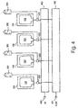
- the device according to the specific implementation comprises the initial blow compressed air source 401 being configured to supply air to an initial blow manifold 400, the initial blow manifold having at least one initial blow control valve 500 and a plurality of initial blow valves 501.
- Components 400, 401, 500 and 501 according to the specific implementation comprise an initial blow system to provide a transporting and effect a providing of compressed air from a compressed air source to a plurality of points of use 102.
- the device further comprises a main blow compressed air source 403 configured to supply compressed air to a main blow manifold 402, manifold 402 comprising at least one main blow control valve 503, being operative to control a plurality of main blow valves 504.
- Components 402, 403, 503 and 504 comprise a main blow system 505 to provide a transporting and effect a providing of compressed air from a compressed air source to the points of use 102.
- the device may further comprise a plurality of restrictor valves 506 configured to restrict the transporting of compressed air from the first compressed air source 401 to the initial blow system 502.
- the blow moulding device is configured for the exhausting of compressed air at the plurality of points of use using a plurality of exhaust valves 300, such exhaust valves being configured with silencers (e.g. sinted bronze silencers).
- the initial blow compressed air source 401 and the main blow compressed air source 403 may comprise any standard air compressor unit capable of supplying compressed air at, 1 x 10 5 Pa to 5 x 10 5 Pa, and 5.5 x 10 5 Pa, respectively.
- the initial blow and main blow manifolds 400 and 402 by way of example, comprise aluminum or stainless steel tubing of internal diameter in the range of 32mm to 55mm.
- the initial blow and main blow control valves may optionally comprise, by way of example, 3 and 4 directional solenoid valves being operable to control the plurality of initial blow and main blow valves, respectively.
- the initial blow and main blow valves may comprise by way of example, pilot operated ISO directional pneumatic valves.
- Restrictors 506 may comprise by way of example, unidirectional flow control valves.
- the exhaust valves being, by way of example, quick exhaust valves.
- Control valves 500 and 503 are controlled by a suitable PLC and the main blow compressed air source 403.
- Initial blow solenoid control valve 500 is configured to control a plurality of initial blow pilot operated valves 501 to effect the providing and exhausting of compressed air.
- main blow solenoid control valve 503 is configured to control the plurality of main blow pilot operated valves 504 to effect the providing and exhausting of compressed air.
- Restrictors 506 are positioned between the first compressed air source 401 and the initial blow pilot operated valve 501.
- the initial blow manifold 400 comprises all connecting tubing between the first compressed air source 401 and initial blow pilot operated valves 501, the initial blow pilot operated valves 501 and initial blow solenoid control valve 500 up to the main blow pilot operated valves.
- the main blow manifold comprises all other tubing connecting, for example, the second compressed air source 403, the main blow control valve 503, the main blow pilot operated valves 504 up to the points of use 102.
- the pilot operated valves 501 and 504 are controlled by the supply of compressed air to a first and a second side of each valve as illustrated in Fig. 6 using standard pneumatic symbolism as is employed in the art. Air flow through each pilot operated valve 501 and 504 may be provided or terminated by the energizing of control valves 500 and 503. The energizing of control valve 500 and 503 involving the supply of an electrical signal from the PLC, for example.
- Fig. 7 there is illustrated a flow diagram detailing the general operational stages of the blow moulding device according to the specific implementation.
- the mould 103 is closed around a blow moulding pin located at a point of use at stage 700.
- a molten material e.g. plastic
- An initial blow is initiated at stage 702 involving the providing and transporting of compressed air from a compressed air source to the plurality of points of use.
- a main blow follows at stage 703 involving the providing and transporting of compressed air from a second compressed air source to the plurality of points of use.
- the compressed air within the plurality of mould cavities, in particular, within the newly formed receptacles, is exhausted at stage 704 via the plurality of exhaust points 300 located in close proximity to the plurality of points of use 102.
- An optional pin cool operation is then initiated at stage 705 involving the providing and transporting of further compressed air to the blow moulding pins, this further compressed air having the effect of cooling the pins which are heated due to the increase in volume experienced by the emergent compressed air entering the mould cavity.
- the compressed air provided for by the optional pin cool operation is exhausted at stage 706 via the same process as described at stage 704, both stages 704 and 706 involving the exhausting of compressed air from within the plurality of mould cavities and not the exhausting of compressed air within the blow moulding device manifold(s).
- a typical cycle time 701 found in the art is between 7 to 10 seconds, such that the inventors provide a blow moulding device capable of a cycle time of less than 7 seconds.
- the mould is opened at stage 707 to allow access to the newly formed receptacle. Following the removing of the receptacle the mould is closed as stage 700 and the cycle repeated.
- Cycle 701 according to the specific implementation of the present invention is controlled by a PLC.
- the initial blow moulding device status is illustrated in Fig. 8 according to the specific implementation.
- the initial and main blow control valves, 500 and 503, are de-energized at stage 800, in that no electrical signal is supplied to valves 500 or 503.
- Compressed air is transported from the first compressed air source 401 via restrictors 506 into the initial blow valves 501 at status 801.
- Compressed air is transported from the second compressed air source 403 via the initial blow control valve 500 into each initial blow valve 501 at status 802.
- the first side of each initial blow valve is opened at status 803.
- compressed air cannot flow through the initial blow valves into the so connected main blow valves 504 at status 804. Consequently, compressed air cannot flow into the plurality of moulds positioned around the plurality of points of use 102 at status 805.
- Control valve 500 is energized at stage 900 employing a suitable electrical signal generated, optionally, by a PLC.
- a suitable electrical signal generated, optionally, by a PLC.
- the direction of air flow through valve 500 is switched resulting in the first side of each initial blow valve being closed at stage 901, and the second side of each initial blow valve being opened at stage 902.
- Compressed air from air source 401 is then transported through each initial blow valve and each main blow valve at stage 903.
- compressed air flows from each main blow valve, through each quick exhaust valve, and into the plurality of moulds situated at the plurality of points of use 102 at stage 904.
- the molten material to be deformed at each point of use, and in particular each blow moulding pin is blown to an initial blow state at stage 905 as a result of the incident compressed air.
- the initial blow state being the pre-forming of the receptacle.
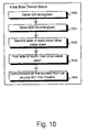
- Valve 500 is energized at status 1000, control valve 503 being de-energized at status 1001.
- the second side of each initial blow valve is open at status 1002 and the first side of each main blow valve being open at status 1003.
- compressed air is transported from air source 401 to the plurality of points of use 102 within the plurality of moulds at status 1004.
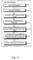
- valve 500 remains energized at stage 900, valve 503 is also energized at stage 1100 resulting in the first side of each main blow valve being closed at stage 1101 and the second side of each main blow valve being opened at stage 1102.
- compressed air is transported from air source 403 through each main blow valve at stage 1103, through each quick exhaust valve and into each of the plurality of moulds at the plurality of points of use at stage 1104.
- the receptacle is forced against the inside walls of the mould cavity 103, thereby forming an entity in a final blown state at stage 1105.
- Valve 500 is energized at status 1000 together with valve 503 at status 1200. Accordingly, the second side of each initial blow valve is open at status 1002 as a result of the energized valve 500 and the second side of each main blow valve is open at status 1201 as a result of the energized valve 503. Consequently, air is provided at the plurality of points of use from air source 403 and transported into the moulds at status 1202.
- FIG. 13 there is illustrated the exhaust operation of compressed air from within the plurality of moulds at the plurality of points of use 102 according to the specific implementation of the present invention.
- Valve 500 is de-energized at stage 1300 together with valve 503 at stage 1301. Accordingly, the second side of each initial blow valve is closed while the first side is opened as a result of the de-energizing of valve 500 at stage 1302. Additionally, the second side of each main blow valve is closed, while the first side is opened as a result of the de-energizing of valve 503 at stage 1303. Due to the de-energizing of both control valve 500 and 503 compressed air from within the plurality of moulds is exhausted via the exhaust valves 300 at stage 1304.
- Silencers may be provided on each quick exhaust valve so as to reduce level of noise when exhausting compressed air into the atmosphere.
- compressed air within the main blow manifold 402 and the initial blow manifold 400 is not exhausted as a consequence of the specific implementation of the present invention.
- FIG. 14 there is illustrated the post exhaust status of the blow moulding device according to the specific implementation.
- Control valves 500 and 503 are de-energized at status 800 such that compressed air cannot be transported into the moulds.
- Compressed air in the initial blow manifold is not exhausted at status 1400 together with compressed air in the main blow manifold not being exhausted at status 1401.
- Compressed air from within the plurality of moulds located at the points of use 102 is exhausted by the plurality of exhaust valves 300 positioned in close proximity to the points of use 102 at status 1402.
- a pin cool operation may be performed as part of the blow moulding cycle using the blow moulding device according to the specific implementation.
- the purpose of the mould pin cool operation is to reduce the temperature of the mould pins following the initial blow and main blow operations.
- Control valve 500 is de-energized at stage 1300 while valve 503 is energized at stage 1100.
- the first side of each main blow valve is closed at stage 1101 while the second side of each valve is opened at stage 1102.
- compressed air is transported from air source 403 to each main blow valve at stage 1103 and over the plurality of mould pins being located at the plurality of points of use 102 at stage 1500.
- the mould pins are cooled at stage 1501 due to the passage of compressed air over their surface.
- the compressed air now present within the plurality of moulds as a result of the pin cool operation is exhausted at stage 1502 according to the exhaust operation as detailed with reference to Fig. 13.
- a method for the providing and exhausting of compressed air at a plurality of points of use, involving the providing of compressed air to the points of use from a first and a second compressed air source.
- the transporting and effecting a provision of compressed air from the first compressed air source 401 is possible due to the utilization of the initial blow system as detailed with reference to Fig. 5.
- the transporting and the effecting a provision of compressed air from the second compressed air source 403 is possible due to the utilization of the main blow system as detailed with reference to Fig. 5.
- the exhausting of compressed air at the points of use is provided while compressed air within the initial blow system, main blow system, or blow moulding device manifold is not exhausted.
- further compressed air is supplied to the plurality of points of use as detailed in the pin cool operation with reference to Fig. 15. This further compressed air being exhausted at the points of use without resort to the exhausting of compressed air within the initial and main blow manifolds.
- a blow moulding device configured to provide and exhaust compressed air at a plurality of points of use involving the providing of compressed air from a single compressed air source as detailed with reference to Fig. 16.
- the further specific implementation comprises a single compressed air source 1600, this compressed air source being configurable to supply or provide compressed air at relatively high pressures within the range 2.5 x 10 6 Pa to 4.5 x 10 6 Pa and the relative low compressed air pressure of substantially 5.5 x 10 5 Pa.
- the relative high pressure implementation being usable to blow mould HDPs, polyethene, glass and the like, while the relative low pressure implementation is usable with LDPs, easily deformable materials and the like.
- Each relative high and low pressure implementation utilizing a similar configuration and array of components as detailed with reference to the specific implementation detailed in Figs. 4 to 15.
- the further specific implementation comprises a compressed air manifold to allow a transporting of the compressed air from the compressed air source 1600 to a plurality of points of use 1605.
- the further specific implementation also comprises a plurality of valves to effect the providing and exhausting of compressed air at the points of use, the plurality of valves comprising at least one control valve 1602 to control a plurality of pilot operated valves 1603.
- a plurality of exhaust valves and silencers are provided 1604 to allow exhausting of the compressed air at the plurality of points of use.
- the further specific implementation may comprise an exhaust air expansion vessel 1606 being connected to the plurality of points of use, the exhaust air expansion vessel being configured with at least one exhaust such that compressed air exhausted from the plurality of points of use can be expanded within vessel 1606 and subsequently exhausted through its exhaust valve.
- This further specific implementation has the benefit of exhausting compressed air at a reduced pressure compared with the exhausting of compressed air directly at the points of use in the event of the use of compressed air at pressure substantially within the range 2.5 x 10 6 Pa to 4.5 x 10 6 Pa.
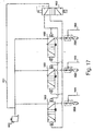
- Fig. 17 there is illustrated a plan view of the blow moulding device according to the further specific implementation comprising a compressed air source 1600, a compressed air manifold 1601, at least one control valve 1602, a plurality of valves 1603, a plurality of exhausts 1604 and a plurality of points of use 1605.
- the operational nature of the device according to the further specific implementation is akin to the operational nature of the device with reference Figs. 4 to 15, in that the solenoid control valve 1602 may be energized by a suitable PLC such that the supply of compressed air to a first side of each pilot operated valve 1603 is switched to a second side as a result of the energizing of control valve 1602. Accordingly, and as detailed with reference to Figs.
- Manifold 1601 comprises all connecting tubing between components 1600, 1602, 1603 and 1604.
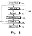
- the blow moulding device being similar in operation to the device as detailed with reference to Fig. 7 is configured to perform a series of blow moulding cycles starting with the closing of the mould at stage 700 with reference to Fig. 18.
- the blow moulding cycle 1800 is then initiated comprising a main blow 703 as detailed, in part with reference to Fig. 11, involving the use of a single control valve. Compressed air at the points of use is then exhausted at stage 704 as detailed, in part, with reference to Fig. 13.
- a pin cool operation may be undertaken at stage 705 as detailed with reference to Fig. 15, this requiring an additional exhaust operation 706 again, as detailed with reference to Fig. 13.
- the mould cavity may be opened at stage 707 to remove the deformed, moulded or blown receptacle.
- FIG. 19 there is illustrated an exhaust air expansion vessel 1606 being connected to the plurality of points of use 102/1605 via the plurality of exhausts 300/1604.
- the exhaust valves being connected to the plurality of pilot operated valves 504/1603.
- the expansion vessel 1606 comprises an exhaust 1900 fitted with a suitable silencer such that exhausted compressed air, from exhaust valves 300/1604, positioned at the points of use, is expanded within the expansion vessel and exhausted by exhaust valve 1900.
- the connecting of expansion vessel 1606 to the points of use is via tubing, forming manifold(s) 400/402/1601.
- expansion vessel 1606, useable with the specific implementation and further specific implementations of the present invention reduces the pressure of the compressed air previously contained within the plurality of moulds 103 prior to a final exhausting of compressed air into the atmosphere.
- the exhausting of compressed air into the expansion vessel 1606 occurs following stage 704 and stage 706 within the blow moulding cycle 701. Similariy, the exhausting of compressed air into expansion vessel 1606 occurs following stage 704 and stage 706 within cycle 1800 as detailed with reference to Fig. 18 according to the further specific implementation of the present invention.
Landscapes
- Engineering & Computer Science (AREA)
- Manufacturing & Machinery (AREA)
- Mechanical Engineering (AREA)
- Fluid-Pressure Circuits (AREA)
- Blow-Moulding Or Thermoforming Of Plastics Or The Like (AREA)
- Exhaust Gas Treatment By Means Of Catalyst (AREA)
Claims (22)
- Blasformvorrichtung, dazu konfiguriert, eine Blasformzykluszeit zu verkürzen, wobei die Vorrichtung Folgendes umfasst:eine Druckluftquelle (401, 403, 1600) zum Bereitstellen von Druckluft an mehreren Verwendungspunkten (102, 1605);Einen Druckluftverteiler (400, 402, 1601), um das Transportieren der Druckluft an die Verwendungspunkte zu ermöglichen;mehrere Abluftventile (300, 1604), um die Druckluft abzulassen;mehrere Ventile (501, 504, 1603), um die Bereitstellung und das Ablassen der Druckluft zu bewirken;mindestens ein Steuerventil (500, 503, 1602), um die mehreren Ventile zu steuern;wobei die Vorrichtung dadurch gekennzeichnet ist, dass:jedes Abluftventil der mehreren Abluftventile jeweils an einem anderen Punkt der mehreren Verwendungspunkte positioniert ist; undjeder Verwendungspunkt der mehreren Verwendungspunkte dazu konfiguriert ist, Druckluft an eine jeweils andere Form (103) von mehreren Formen zu liefern.
- Vorrichtung nach Anspruch 1, wobei die mehreren Ventile mehrere vorgesteuerte Ventile umfassen, um die Bereitstellung und das Ablassen der Druckluft zu bewirken; und
das mindestens eine Steuerventil ein Magnetsteuerventil umfasst, um die mehreren vorgesteuerten Ventile zu steuern. - Vorrichtung nach Anspruch 2, wobei das Magnetsteuerventil ein 3- und 4-Wege-Magnetsteuerventil umfasst, das wirksam ist, die mehreren vorgesteuerten Ventile zu steuern.
- Vorrichtung nach einem der vorangehenden Ansprüche, wobei die Vorrichtung weiter eine PLC umfasst, wobei die PLC dazu konfiguriert ist, das Steuerventil zu steuern;
wobei der Luftstrom durch jedes der mehreren Ventile durch ein stromführend Schalten des Steuerventils unter Verwendung der PLC bereitgestellt beziehungsweise beendet werden kann. - Vorrichtung nach Anspruch 4, wobei das Steuerventil dazu konfiguriert ist, durch die Zufuhr eines elektrischen Signals von der PLC stromführend und stromlos geschaltet zu werden;
wobei die mehreren Ventile Pneumatikventile umfassen und die Pneumatikventile durch ein stromführend Schalten und stromlos Schalten des Steuerventils gesteuert werden. - Vorrichtung nach Anspruch 4 oder 5, wobei der Blasformzyklus durch Folgendes gesteuert wird:ein elektrisches Signal, das von der PLC an das Steuerventil übertragen wird;ein stromführend Schalten und stromlos Schalten des Steuerventils; undein Bereitstellen und Beenden des Luftstroms durch die mehreren Ventile;
wobei eine Verkürzung der Blasformzykluszeit bereitgestellt wird. - Vorrichtung nach einem der vorangehenden Ansprüche, die weiter Folgendes umfasst:ein Abluftexpansionsgefäß (1606), das mit den mehreren Verwendungspunkten verbunden ist, wobei das Expansionsgefäß mindestens ein Abluftventil (1900) umfasst;wobei sich abgelassene Druckluft in dem Expansionsgefäß ausdehnt und durch das mindestens eine Abluftventil abgelassen wird.
- Vorrichtung nach einem der vorangehenden Ansprüche, wobei die Abluftventile mit Schalldämpfern konfiguriert sind.
- Vorrichtung nach einem der vorangehenden Ansprüche, wobei die Vorrichtung dazu konfigurierbar ist, die Druckluft an den mehreren Verwendungspunkten mit einem Druck im Wesentlichen im Bereich zwischen 2,5 x 10⁶ Pa und 4,5 x 10⁶ Pa bereitzustellen.
- Vorrichtung nach einem der Ansprüche 1 bis 9, wobei die Vorrichtung dazu konfigurierbar ist, die Druckluft an den mehreren Verwendungspunkten mit einem Druck von im Wesentlichen 5,5 x 10⁵ Pa bereitzustellen.
- Vorrichtung nach einem der vorangehenden Ansprüche, die weiter Folgendes umfasst:eine zweite Druckluftquelle zum Bereitstellen von Druckluft an den mehreren Verwendungspunkten; undeinen zweiten Druckluftverteiler (402), um das Transportieren der Druckluft an die Verwendungspunkte zu ermöglichen;
- Vorrichtung nach Anspruch 11, wobei die mehreren Ventile Folgendes umfassen:mehrere Anfangsblasventile (501), um das Bereitstellen der Druckluft von der Druckluftquelle an die Verwendungspunkte zu bewirken; undmehrere Hauptblasventile (504), um das Bereitstellen der Druckluft von der zweiten Druckluftquelle an die Verwendungspunkte zu bewirken.
- Vorrichtung nach Anspruch 12, wobei das mindestens eine Steuerventil Folgendes umfasst:mindestens ein Anfangsblas-Steuerventil, um die mehreren Anfangsblasventile zu steuern; undmindestens ein Hauptblas-Steuerventil, um die mehreren Hauptblasventile zu steuern.
- Vorrichtung nach Anspruch 13, wobei die Vorrichtung dazu konfigurierbar ist, unter Verwendung der Druckluftquelle Druckluft an den Verwendungspunkten mit einem Druck im Wesentlichen im Bereich zwischen 1 x 10⁵ Pa und 5 x 10⁵ Pa bereitzustellen; und
unter Verwendung der zweiten Druckluftquelle Druckluft an den Verwendungspunkten mit einem Druck von im Wesentlichen 5,5 x 10⁵ Pa bereitzustellen. - Vorrichtung nach einem der Ansprüche 11 bis 14, die weiter Drosselventile (506) umfasst, die dazu konfiguriert sind, das Transportieren der Druckluft von der Druckluftquelle zu drosseln.
- Verfahren zum Blasformen, das dazu konfiguriert ist, eine Blasformzykluszeit zu verkürzen, wobei das Verfahren Folgendes umfasst:Bereitstellen von Druckluft an mehreren Verwendungspunkten (102, 1605) von einer Druckluftquelle (401, 403, 1600);Ablassen der Druckluft an den Verwendungspunkten unter Verwendung mehrerer Abluftventile (300, 1604);Transportieren der Druckluft an die Verwendungspunkte unter Verwendung eines Druckluftverteilers (400, 402, 1601);Bewirken des Bereitstellens und des Ablassens der Druckluft an den Verwendungspunkten unter Verwendung mehrerer Ventile (501, 504, 1603);Steuern der mehreren Ventile unter Verwendung mindestens eines Steuerventils (500, 503, 1602);wobei das Verfahren gekennzeichnet ist durch:Bereitstellen von Druckluft an mehrere Formen, wobei jede Form (103) der mehreren Formen an einem anderen jeweiligen Verwendungspunkt der mehreren Verwendungspunkte positioniert ist; undAblassen von Druckluft aus den mehreren Formen unter Verwendung der mehreren Abluftventile, wobei jedes Abluftventil an einem anderen jeweiligen Verwendungspunkt der mehreren Verwendungspunkte positioniert ist.
- Verfahren nach Anspruch 16, wobei während einem Blasformzyklus Druckluft in den mehreren Formen abgelassen wird und Druckluft in dem Verteiler nicht abgelassen wird.
- Verfahren nach Anspruch 16 oder 17, das weiter Folgendes umfasst:Steuern des mindestens einen Steuerventils unter Verwendung einer PLC;stromführend Schalten und stromlos Schalten des mindestens einen Steuerventils unter Verwendung der PLC;Bereitstellen und Beenden des Luftstroms durch die mehreren Ventile durch stromführend Schalten und stromlos Schalten des mindestens einen Steuerventils.
- Verfahren nach Anspruch 18, wobei die mehreren Ventile mehrere vorgesteuerte Ventile umfassen, um die Bereitstellung und das Ablassen der Druckluft zu bewirken; und
das mindeste eine Steuerventil ein Magnetsteuerventil umfasst, um die mehreren vorgesteuerten Ventile zu steuern. - Verfahren nach einem der Ansprüche 16 bis 19, das weiter Folgendes umfasst:Ablassen der Druckluft aus den Formen in ein Luftexpansionsgefäß (1606);Ausdehnen der Druckluft in dem Gefäß; undAblassen von Luft in dem Gefäß unter Verwendung mindestens eines Abluftventils (1900).
- Verfahren nach einem der Ansprüche 16 bis 20, das weiter Folgendes umfasst:Bereitstellen von Druckluft an den mehreren Verwendungspunkten von einer zweiten Druckluftquelle; undTransportieren der Druckluft von der zweiten Druckluftquelle zu den Verwendungspunkten unter Verwendung eines zweiten Druckluftverteilers.
- Verfahren nach Anspruch 21, das weiter Folgendes umfasst:Steuern mehrerer Anfangsblasventile während eines Anfangsblasformzyklus unter Verwendung mindestens eines Anfangsblas-Steuerventils; undSteuern mehrerer Hauptblasventile während eines Hauptblaszyklus unter Verwendung mindestens eines Hauptblas-Steuerventils.
Applications Claiming Priority (3)
| Application Number | Priority Date | Filing Date | Title |
|---|---|---|---|
| GB0123317 | 2001-09-28 | ||
| GB0123317A GB2380967B (en) | 2001-09-28 | 2001-09-28 | Blow moulding control system |
| PCT/GB2002/004412 WO2003028979A1 (en) | 2001-09-28 | 2002-09-27 | Method and apparatus for providing and exhausting compressed air at a plurality of points of use in a blow moulding device |
Publications (2)
| Publication Number | Publication Date |
|---|---|
| EP1432563A1 EP1432563A1 (de) | 2004-06-30 |
| EP1432563B1 true EP1432563B1 (de) | 2006-01-11 |
Family
ID=9922852
Family Applications (1)
| Application Number | Title | Priority Date | Filing Date |
|---|---|---|---|
| EP02800188A Expired - Lifetime EP1432563B1 (de) | 2001-09-28 | 2002-09-27 | Verfahren und vorrichtung zur bereitstellung von druckbeaufschlagter abgasluft an mehreren verwendungspunkten in einer blasformvorrichtung |
Country Status (6)
| Country | Link |
|---|---|
| US (1) | US7892476B2 (de) |
| EP (1) | EP1432563B1 (de) |
| AT (1) | ATE315466T1 (de) |
| DE (1) | DE60208717D1 (de) |
| GB (1) | GB2380967B (de) |
| WO (1) | WO2003028979A1 (de) |
Families Citing this family (8)
| Publication number | Priority date | Publication date | Assignee | Title |
|---|---|---|---|---|
| GB2380967B (en) | 2001-09-28 | 2003-12-24 | Roton Compressor Services Ltd | Blow moulding control system |
| DE202004021780U1 (de) * | 2004-03-25 | 2010-12-09 | Krones Ag | Vorrichtung zum Herstellen eines insbesondere wärmebeständigen Hohlkörpers |
| US20060197263A1 (en) * | 2005-03-03 | 2006-09-07 | Graham Packaging Company, L.P. | Blow air control system |
| DE102009020738A1 (de) * | 2009-05-11 | 2010-11-25 | Krones Ag | Vorrichtung zum Blasformen von Kunststoffvorformlingen mit reduziertem Totvolumen |
| DE102009023406A1 (de) * | 2009-05-29 | 2010-12-02 | Krones Ag | Blasmaschine mit CIP-Reinigungssystem zur Herstellung von Kunststoff-Flaschen, insbesondere PET-Flaschen |
| CN101963794B (zh) * | 2009-07-21 | 2013-09-04 | 康准电子科技(昆山)有限公司 | 薄膜真空贴附控制方法 |
| US9644646B2 (en) * | 2011-02-18 | 2017-05-09 | Norgren, Inc. | Multiple-staged fluid operated actuator |
| US9199367B2 (en) * | 2011-10-26 | 2015-12-01 | Newpol Machine Works Ltd. | Gas bolt heating apparatus |
Family Cites Families (14)
| Publication number | Priority date | Publication date | Assignee | Title |
|---|---|---|---|---|
| US2375763A (en) * | 1940-07-30 | 1945-05-15 | Olin Ind Inc | Apparatus for shaping tubes |
| US3400636A (en) * | 1966-04-12 | 1968-09-10 | Ervin J. Schneider | Pneumatic circuit for rapidly transferring fluid under pressure from a work cylinderto a storage tank for subsequent use |
| FR1600585A (de) * | 1968-12-27 | 1970-07-27 | ||
| FR2405809A1 (fr) * | 1977-06-30 | 1979-05-11 | Air Liquide | Procede de refroidissement d'un corps creux en materiau thermoplastique et dispositif de formage de corps creux en materiau thermoplastique |
| JPS5850572B2 (ja) | 1980-05-09 | 1983-11-11 | 大同酸素株式会社 | ブロ−ガス回収を伴う中空成形品の製造方法 |
| JPS63134220A (ja) * | 1986-11-26 | 1988-06-06 | Kao Corp | ブロ−成形機の制御方法及びその装置 |
| US4790741A (en) * | 1987-08-07 | 1988-12-13 | Toyo Seikan Kaisha, Ltd. | Apparatus for preparing heat-set plastic hollow vessel |
| US5229043A (en) | 1992-03-10 | 1993-07-20 | The Boc Group, Inc. | Blow molding method and apparatus employing pressurized liquid cryogen vaporized by recovered gaseous cryogen |
| DE4340291A1 (de) * | 1993-11-26 | 1995-06-01 | Krupp Corpoplast Masch | Mehrfachnutzung von Blasluft |
| IES950446A2 (en) * | 1995-06-19 | 1995-12-13 | Menza Ltd | Blow moulding method and apparatus |
| WO1998038027A1 (en) | 1995-11-13 | 1998-09-03 | Kao Corporation | Blow molding method |
| US5851479A (en) * | 1996-12-24 | 1998-12-22 | Owens-Brockway Plastic Products Inc. | Method and apparatus for blow molding hollow articles |
| GB2380967B (en) | 2001-09-28 | 2003-12-24 | Roton Compressor Services Ltd | Blow moulding control system |
| US6855289B2 (en) * | 2001-11-27 | 2005-02-15 | Graham Packaging Pet Technologies, Inc. | Method and apparatus for cooling during in-mold handle attachment |
-
2001
- 2001-09-28 GB GB0123317A patent/GB2380967B/en not_active Expired - Lifetime
-
2002
- 2002-09-27 EP EP02800188A patent/EP1432563B1/de not_active Expired - Lifetime
- 2002-09-27 AT AT02800188T patent/ATE315466T1/de not_active IP Right Cessation
- 2002-09-27 WO PCT/GB2002/004412 patent/WO2003028979A1/en not_active Ceased
- 2002-09-27 US US10/490,915 patent/US7892476B2/en not_active Expired - Fee Related
- 2002-09-27 DE DE60208717T patent/DE60208717D1/de not_active Expired - Lifetime
Also Published As
| Publication number | Publication date |
|---|---|
| GB0123317D0 (en) | 2001-11-21 |
| ATE315466T1 (de) | 2006-02-15 |
| US20040265416A1 (en) | 2004-12-30 |
| WO2003028979A1 (en) | 2003-04-10 |
| US7892476B2 (en) | 2011-02-22 |
| EP1432563A1 (de) | 2004-06-30 |
| GB2380967A (en) | 2003-04-23 |
| DE60208717D1 (de) | 2006-04-06 |
| GB2380967B (en) | 2003-12-24 |
Similar Documents
| Publication | Publication Date | Title |
|---|---|---|
| US5648026A (en) | Multiple utilization of blow-mold air | |
| US9102090B2 (en) | Method and device for blow molding containers | |
| US6749415B2 (en) | Blow molding machine for producing pasteurizable containers | |
| EP2112969B1 (de) | Formkühlung durch energierückgewinnung aus verbrauchter druckluft beim blasformprozess | |
| US7892476B2 (en) | Method and apparatus for providing and exhausting compressed air at a plurality of points of use in a blow moulding device | |
| US5585066A (en) | Multiple utilization of working air | |
| CN111315555B (zh) | 拉伸吹塑成型装置和吹塑成型方法 | |
| US8871138B2 (en) | Method and device for blow-molding containers | |
| US11707874B2 (en) | Apparatus for cooling and handling preforms in plastic material | |
| JP2007504021A (ja) | 容器ブロー成形方法および装置 | |
| JP2013518748A (ja) | 容器のブロー成形方法およびブロー成形装置 | |
| CN114311457A (zh) | 一种热塑性塑料中空成型方法 | |
| US7503760B2 (en) | Method and apparatus for blow molding | |
| JP2007504020A (ja) | 工作物ブロー成形方法および装置 | |
| JP2001287917A (ja) | I.s.マシーン用ブランク金型の弁装置 | |
| WO1998038027A1 (en) | Blow molding method | |
| JPH06315973A (ja) | 成形装置 | |
| JP5081839B2 (ja) | 容器をブロー成形するための方法および装置 | |
| JP3843335B2 (ja) | 壜体のブロー成形方法 | |
| JP2003103615A (ja) | 中空容器のブロー成形方法およびブロー成形装置 | |
| JPS63134220A (ja) | ブロ−成形機の制御方法及びその装置 | |
| WO2008011702A1 (en) | Pneumatic structure | |
| CA3037816C (en) | Apparatus for cooling and handling preforms in plastic material | |
| CN101963794B (zh) | 薄膜真空贴附控制方法 | |
| JP2001205331A (ja) | 金型冷却装置 |
Legal Events
| Date | Code | Title | Description |
|---|---|---|---|
| PUAI | Public reference made under article 153(3) epc to a published international application that has entered the european phase |
Free format text: ORIGINAL CODE: 0009012 |
|
| 17P | Request for examination filed |
Effective date: 20040428 |
|
| AK | Designated contracting states |
Kind code of ref document: A1 Designated state(s): AT BE BG CH CY CZ DE DK EE ES FI FR GB GR IE IT LI LU MC NL PT SE SK TR |
|
| AX | Request for extension of the european patent |
Extension state: AL LT LV MK RO SI |
|
| 17Q | First examination report despatched |
Effective date: 20040720 |
|
| GRAP | Despatch of communication of intention to grant a patent |
Free format text: ORIGINAL CODE: EPIDOSNIGR1 |
|
| GRAS | Grant fee paid |
Free format text: ORIGINAL CODE: EPIDOSNIGR3 |
|
| GRAA | (expected) grant |
Free format text: ORIGINAL CODE: 0009210 |
|
| AK | Designated contracting states |
Kind code of ref document: B1 Designated state(s): AT BE BG CH CY CZ DE DK EE ES FI FR GB GR IE IT LI LU MC NL PT SE SK TR |
|
| PG25 | Lapsed in a contracting state [announced via postgrant information from national office to epo] |
Ref country code: IT Free format text: LAPSE BECAUSE OF FAILURE TO SUBMIT A TRANSLATION OF THE DESCRIPTION OR TO PAY THE FEE WITHIN THE PRESCRIBED TIME-LIMIT;WARNING: LAPSES OF ITALIAN PATENTS WITH EFFECTIVE DATE BEFORE 2007 MAY HAVE OCCURRED AT ANY TIME BEFORE 2007. THE CORRECT EFFECTIVE DATE MAY BE DIFFERENT FROM THE ONE RECORDED. Effective date: 20060111 Ref country code: BE Free format text: LAPSE BECAUSE OF FAILURE TO SUBMIT A TRANSLATION OF THE DESCRIPTION OR TO PAY THE FEE WITHIN THE PRESCRIBED TIME-LIMIT Effective date: 20060111 Ref country code: FI Free format text: LAPSE BECAUSE OF FAILURE TO SUBMIT A TRANSLATION OF THE DESCRIPTION OR TO PAY THE FEE WITHIN THE PRESCRIBED TIME-LIMIT Effective date: 20060111 Ref country code: NL Free format text: LAPSE BECAUSE OF FAILURE TO SUBMIT A TRANSLATION OF THE DESCRIPTION OR TO PAY THE FEE WITHIN THE PRESCRIBED TIME-LIMIT Effective date: 20060111 Ref country code: SK Free format text: LAPSE BECAUSE OF FAILURE TO SUBMIT A TRANSLATION OF THE DESCRIPTION OR TO PAY THE FEE WITHIN THE PRESCRIBED TIME-LIMIT Effective date: 20060111 Ref country code: CH Free format text: LAPSE BECAUSE OF FAILURE TO SUBMIT A TRANSLATION OF THE DESCRIPTION OR TO PAY THE FEE WITHIN THE PRESCRIBED TIME-LIMIT Effective date: 20060111 Ref country code: AT Free format text: LAPSE BECAUSE OF FAILURE TO SUBMIT A TRANSLATION OF THE DESCRIPTION OR TO PAY THE FEE WITHIN THE PRESCRIBED TIME-LIMIT Effective date: 20060111 Ref country code: LI Free format text: LAPSE BECAUSE OF FAILURE TO SUBMIT A TRANSLATION OF THE DESCRIPTION OR TO PAY THE FEE WITHIN THE PRESCRIBED TIME-LIMIT Effective date: 20060111 |
|
| REG | Reference to a national code |
Ref country code: CH Ref legal event code: EP |
|
| REG | Reference to a national code |
Ref country code: IE Ref legal event code: FG4D |
|
| REF | Corresponds to: |
Ref document number: 60208717 Country of ref document: DE Date of ref document: 20060406 Kind code of ref document: P |
|
| PG25 | Lapsed in a contracting state [announced via postgrant information from national office to epo] |
Ref country code: DK Free format text: LAPSE BECAUSE OF FAILURE TO SUBMIT A TRANSLATION OF THE DESCRIPTION OR TO PAY THE FEE WITHIN THE PRESCRIBED TIME-LIMIT Effective date: 20060411 Ref country code: BG Free format text: LAPSE BECAUSE OF FAILURE TO SUBMIT A TRANSLATION OF THE DESCRIPTION OR TO PAY THE FEE WITHIN THE PRESCRIBED TIME-LIMIT Effective date: 20060411 Ref country code: SE Free format text: LAPSE BECAUSE OF FAILURE TO SUBMIT A TRANSLATION OF THE DESCRIPTION OR TO PAY THE FEE WITHIN THE PRESCRIBED TIME-LIMIT Effective date: 20060411 |
|
| PG25 | Lapsed in a contracting state [announced via postgrant information from national office to epo] |
Ref country code: DE Free format text: LAPSE BECAUSE OF FAILURE TO SUBMIT A TRANSLATION OF THE DESCRIPTION OR TO PAY THE FEE WITHIN THE PRESCRIBED TIME-LIMIT Effective date: 20060412 |
|
| PG25 | Lapsed in a contracting state [announced via postgrant information from national office to epo] |
Ref country code: ES Free format text: LAPSE BECAUSE OF FAILURE TO SUBMIT A TRANSLATION OF THE DESCRIPTION OR TO PAY THE FEE WITHIN THE PRESCRIBED TIME-LIMIT Effective date: 20060422 |
|
| PG25 | Lapsed in a contracting state [announced via postgrant information from national office to epo] |
Ref country code: PT Free format text: LAPSE BECAUSE OF FAILURE TO SUBMIT A TRANSLATION OF THE DESCRIPTION OR TO PAY THE FEE WITHIN THE PRESCRIBED TIME-LIMIT Effective date: 20060612 |
|
| NLV1 | Nl: lapsed or annulled due to failure to fulfill the requirements of art. 29p and 29m of the patents act | ||
| REG | Reference to a national code |
Ref country code: CH Ref legal event code: PL |
|
| PG25 | Lapsed in a contracting state [announced via postgrant information from national office to epo] |
Ref country code: IE Free format text: LAPSE BECAUSE OF NON-PAYMENT OF DUE FEES Effective date: 20060927 |
|
| PG25 | Lapsed in a contracting state [announced via postgrant information from national office to epo] |
Ref country code: MC Free format text: LAPSE BECAUSE OF NON-PAYMENT OF DUE FEES Effective date: 20060930 |
|
| PLBE | No opposition filed within time limit |
Free format text: ORIGINAL CODE: 0009261 |
|
| STAA | Information on the status of an ep patent application or granted ep patent |
Free format text: STATUS: NO OPPOSITION FILED WITHIN TIME LIMIT |
|
| 26N | No opposition filed |
Effective date: 20061012 |
|
| EN | Fr: translation not filed | ||
| GBPC | Gb: european patent ceased through non-payment of renewal fee |
Effective date: 20060927 |
|
| PG25 | Lapsed in a contracting state [announced via postgrant information from national office to epo] |
Ref country code: GB Free format text: LAPSE BECAUSE OF NON-PAYMENT OF DUE FEES Effective date: 20060927 |
|
| PG25 | Lapsed in a contracting state [announced via postgrant information from national office to epo] |
Ref country code: FR Free format text: LAPSE BECAUSE OF FAILURE TO SUBMIT A TRANSLATION OF THE DESCRIPTION OR TO PAY THE FEE WITHIN THE PRESCRIBED TIME-LIMIT Effective date: 20070302 Ref country code: CZ Free format text: LAPSE BECAUSE OF FAILURE TO SUBMIT A TRANSLATION OF THE DESCRIPTION OR TO PAY THE FEE WITHIN THE PRESCRIBED TIME-LIMIT Effective date: 20060111 Ref country code: GR Free format text: LAPSE BECAUSE OF FAILURE TO SUBMIT A TRANSLATION OF THE DESCRIPTION OR TO PAY THE FEE WITHIN THE PRESCRIBED TIME-LIMIT Effective date: 20060412 |
|
| PG25 | Lapsed in a contracting state [announced via postgrant information from national office to epo] |
Ref country code: EE Free format text: LAPSE BECAUSE OF FAILURE TO SUBMIT A TRANSLATION OF THE DESCRIPTION OR TO PAY THE FEE WITHIN THE PRESCRIBED TIME-LIMIT Effective date: 20060111 |
|
| PG25 | Lapsed in a contracting state [announced via postgrant information from national office to epo] |
Ref country code: LU Free format text: LAPSE BECAUSE OF NON-PAYMENT OF DUE FEES Effective date: 20060927 Ref country code: TR Free format text: LAPSE BECAUSE OF FAILURE TO SUBMIT A TRANSLATION OF THE DESCRIPTION OR TO PAY THE FEE WITHIN THE PRESCRIBED TIME-LIMIT Effective date: 20060111 |
|
| PG25 | Lapsed in a contracting state [announced via postgrant information from national office to epo] |
Ref country code: FR Free format text: LAPSE BECAUSE OF FAILURE TO SUBMIT A TRANSLATION OF THE DESCRIPTION OR TO PAY THE FEE WITHIN THE PRESCRIBED TIME-LIMIT Effective date: 20060111 Ref country code: CY Free format text: LAPSE BECAUSE OF FAILURE TO SUBMIT A TRANSLATION OF THE DESCRIPTION OR TO PAY THE FEE WITHIN THE PRESCRIBED TIME-LIMIT Effective date: 20060111 |