EP1432654B1 - Verfahren und vorrichtung zum schmelzen von glas mittels einem induktionsbeheizten skulltiegel - Google Patents
Verfahren und vorrichtung zum schmelzen von glas mittels einem induktionsbeheizten skulltiegel Download PDFInfo
- Publication number
- EP1432654B1 EP1432654B1 EP02785144A EP02785144A EP1432654B1 EP 1432654 B1 EP1432654 B1 EP 1432654B1 EP 02785144 A EP02785144 A EP 02785144A EP 02785144 A EP02785144 A EP 02785144A EP 1432654 B1 EP1432654 B1 EP 1432654B1
- Authority
- EP
- European Patent Office
- Prior art keywords
- glass
- crucible
- bridge
- outlet
- melt
- Prior art date
- Legal status (The legal status is an assumption and is not a legal conclusion. Google has not performed a legal analysis and makes no representation as to the accuracy of the status listed.)
- Expired - Lifetime
Links
- 239000011521 glass Substances 0.000 title claims abstract description 91
- 238000002844 melting Methods 0.000 title claims abstract description 41
- 230000008018 melting Effects 0.000 title claims abstract description 36
- 238000000034 method Methods 0.000 title claims abstract description 16
- 239000000155 melt Substances 0.000 claims abstract description 32
- 210000003625 skull Anatomy 0.000 claims abstract description 31
- 239000006060 molten glass Substances 0.000 claims abstract description 11
- 238000010438 heat treatment Methods 0.000 claims abstract description 9
- 230000000717 retained effect Effects 0.000 claims abstract description 3
- 229910052751 metal Inorganic materials 0.000 claims description 17
- 239000002184 metal Substances 0.000 claims description 17
- 230000006698 induction Effects 0.000 claims description 14
- 238000012545 processing Methods 0.000 claims description 10
- 230000005587 bubbling Effects 0.000 claims description 8
- 239000002826 coolant Substances 0.000 claims description 7
- 239000000156 glass melt Substances 0.000 claims description 7
- 238000010924 continuous production Methods 0.000 claims description 4
- 235000001674 Agaricus brunnescens Nutrition 0.000 claims description 2
- 239000000470 constituent Substances 0.000 claims description 2
- 238000005266 casting Methods 0.000 claims 2
- BASFCYQUMIYNBI-UHFFFAOYSA-N platinum Chemical compound [Pt] BASFCYQUMIYNBI-UHFFFAOYSA-N 0.000 description 25
- 229910052697 platinum Inorganic materials 0.000 description 11
- 238000007670 refining Methods 0.000 description 9
- 238000001816 cooling Methods 0.000 description 8
- 239000000203 mixture Substances 0.000 description 8
- 239000011248 coating agent Substances 0.000 description 7
- 238000000576 coating method Methods 0.000 description 7
- 230000000694 effects Effects 0.000 description 7
- 230000008901 benefit Effects 0.000 description 6
- 239000000463 material Substances 0.000 description 6
- 239000004033 plastic Substances 0.000 description 5
- 229920003023 plastic Polymers 0.000 description 5
- 230000007797 corrosion Effects 0.000 description 4
- 238000005260 corrosion Methods 0.000 description 4
- RYGMFSIKBFXOCR-UHFFFAOYSA-N Copper Chemical compound [Cu] RYGMFSIKBFXOCR-UHFFFAOYSA-N 0.000 description 3
- 238000003723 Smelting Methods 0.000 description 3
- 239000010949 copper Substances 0.000 description 3
- 229910052802 copper Inorganic materials 0.000 description 3
- 238000005516 engineering process Methods 0.000 description 3
- 230000002349 favourable effect Effects 0.000 description 3
- 238000007654 immersion Methods 0.000 description 3
- 229910001220 stainless steel Inorganic materials 0.000 description 3
- 239000010935 stainless steel Substances 0.000 description 3
- XLYOFNOQVPJJNP-UHFFFAOYSA-N water Substances O XLYOFNOQVPJJNP-UHFFFAOYSA-N 0.000 description 3
- 239000006105 batch ingredient Substances 0.000 description 2
- 238000000354 decomposition reaction Methods 0.000 description 2
- 238000013461 design Methods 0.000 description 2
- 238000001704 evaporation Methods 0.000 description 2
- 230000008014 freezing Effects 0.000 description 2
- 238000007710 freezing Methods 0.000 description 2
- 239000007789 gas Substances 0.000 description 2
- 230000000670 limiting effect Effects 0.000 description 2
- 239000010445 mica Substances 0.000 description 2
- 229910052618 mica group Inorganic materials 0.000 description 2
- 230000005855 radiation Effects 0.000 description 2
- 230000002829 reductive effect Effects 0.000 description 2
- 239000011819 refractory material Substances 0.000 description 2
- 239000000126 substance Substances 0.000 description 2
- 238000012549 training Methods 0.000 description 2
- 229910018072 Al 2 O 3 Inorganic materials 0.000 description 1
- 229910018068 Li 2 O Inorganic materials 0.000 description 1
- 229910004298 SiO 2 Inorganic materials 0.000 description 1
- 229910010413 TiO 2 Inorganic materials 0.000 description 1
- 230000001133 acceleration Effects 0.000 description 1
- 230000009471 action Effects 0.000 description 1
- 229910052782 aluminium Inorganic materials 0.000 description 1
- XAGFODPZIPBFFR-UHFFFAOYSA-N aluminium Chemical compound [Al] XAGFODPZIPBFFR-UHFFFAOYSA-N 0.000 description 1
- 239000005354 aluminosilicate glass Substances 0.000 description 1
- 238000000137 annealing Methods 0.000 description 1
- QVGXLLKOCUKJST-UHFFFAOYSA-N atomic oxygen Chemical compound [O] QVGXLLKOCUKJST-UHFFFAOYSA-N 0.000 description 1
- 230000009286 beneficial effect Effects 0.000 description 1
- 230000015572 biosynthetic process Effects 0.000 description 1
- 238000006243 chemical reaction Methods 0.000 description 1
- 238000010276 construction Methods 0.000 description 1
- 238000011109 contamination Methods 0.000 description 1
- 238000009749 continuous casting Methods 0.000 description 1
- 230000008878 coupling Effects 0.000 description 1
- 238000010168 coupling process Methods 0.000 description 1
- 238000005859 coupling reaction Methods 0.000 description 1
- 230000006735 deficit Effects 0.000 description 1
- 210000003298 dental enamel Anatomy 0.000 description 1
- 238000007599 discharging Methods 0.000 description 1
- 238000011143 downstream manufacturing Methods 0.000 description 1
- 238000010292 electrical insulation Methods 0.000 description 1
- 230000008020 evaporation Effects 0.000 description 1
- 238000002474 experimental method Methods 0.000 description 1
- 238000011049 filling Methods 0.000 description 1
- 229910052731 fluorine Inorganic materials 0.000 description 1
- 239000011737 fluorine Substances 0.000 description 1
- 238000007499 fusion processing Methods 0.000 description 1
- 230000009477 glass transition Effects 0.000 description 1
- 238000000265 homogenisation Methods 0.000 description 1
- 230000001771 impaired effect Effects 0.000 description 1
- 230000006872 improvement Effects 0.000 description 1
- 238000003780 insertion Methods 0.000 description 1
- 230000037431 insertion Effects 0.000 description 1
- 230000002452 interceptive effect Effects 0.000 description 1
- 230000014759 maintenance of location Effects 0.000 description 1
- 238000010309 melting process Methods 0.000 description 1
- 239000012811 non-conductive material Substances 0.000 description 1
- 239000001301 oxygen Substances 0.000 description 1
- 229910052760 oxygen Inorganic materials 0.000 description 1
- 239000004810 polytetrafluoroethylene Substances 0.000 description 1
- 229920001343 polytetrafluoroethylene Polymers 0.000 description 1
- 239000010970 precious metal Substances 0.000 description 1
- 230000008569 process Effects 0.000 description 1
- 239000011241 protective layer Substances 0.000 description 1
- 238000000746 purification Methods 0.000 description 1
- 239000010453 quartz Substances 0.000 description 1
- 238000007789 sealing Methods 0.000 description 1
- 238000000926 separation method Methods 0.000 description 1
- 238000007493 shaping process Methods 0.000 description 1
- VYPSYNLAJGMNEJ-UHFFFAOYSA-N silicon dioxide Inorganic materials O=[Si]=O VYPSYNLAJGMNEJ-UHFFFAOYSA-N 0.000 description 1
- 229910000679 solder Inorganic materials 0.000 description 1
- 238000005507 spraying Methods 0.000 description 1
- 238000003756 stirring Methods 0.000 description 1
- 230000002123 temporal effect Effects 0.000 description 1
Images



Classifications
-
- C—CHEMISTRY; METALLURGY
- C03—GLASS; MINERAL OR SLAG WOOL
- C03B—MANUFACTURE, SHAPING, OR SUPPLEMENTARY PROCESSES
- C03B5/00—Melting in furnaces; Furnaces so far as specially adapted for glass manufacture
- C03B5/16—Special features of the melting process; Auxiliary means specially adapted for glass-melting furnaces
- C03B5/18—Stirring devices; Homogenisation
- C03B5/193—Stirring devices; Homogenisation using gas, e.g. bubblers
-
- C—CHEMISTRY; METALLURGY
- C03—GLASS; MINERAL OR SLAG WOOL
- C03B—MANUFACTURE, SHAPING, OR SUPPLEMENTARY PROCESSES
- C03B1/00—Preparing the batches
- C03B1/02—Compacting the glass batches, e.g. pelletising
-
- C—CHEMISTRY; METALLURGY
- C03—GLASS; MINERAL OR SLAG WOOL
- C03B—MANUFACTURE, SHAPING, OR SUPPLEMENTARY PROCESSES
- C03B3/00—Charging the melting furnaces
-
- C—CHEMISTRY; METALLURGY
- C03—GLASS; MINERAL OR SLAG WOOL
- C03B—MANUFACTURE, SHAPING, OR SUPPLEMENTARY PROCESSES
- C03B5/00—Melting in furnaces; Furnaces so far as specially adapted for glass manufacture
- C03B5/02—Melting in furnaces; Furnaces so far as specially adapted for glass manufacture in electric furnaces, e.g. by dielectric heating
- C03B5/021—Melting in furnaces; Furnaces so far as specially adapted for glass manufacture in electric furnaces, e.g. by dielectric heating by induction heating
-
- C—CHEMISTRY; METALLURGY
- C03—GLASS; MINERAL OR SLAG WOOL
- C03B—MANUFACTURE, SHAPING, OR SUPPLEMENTARY PROCESSES
- C03B5/00—Melting in furnaces; Furnaces so far as specially adapted for glass manufacture
- C03B5/16—Special features of the melting process; Auxiliary means specially adapted for glass-melting furnaces
- C03B5/18—Stirring devices; Homogenisation
-
- C—CHEMISTRY; METALLURGY
- C03—GLASS; MINERAL OR SLAG WOOL
- C03B—MANUFACTURE, SHAPING, OR SUPPLEMENTARY PROCESSES
- C03B5/00—Melting in furnaces; Furnaces so far as specially adapted for glass manufacture
- C03B5/16—Special features of the melting process; Auxiliary means specially adapted for glass-melting furnaces
- C03B5/18—Stirring devices; Homogenisation
- C03B5/187—Stirring devices; Homogenisation with moving elements
-
- C—CHEMISTRY; METALLURGY
- C03—GLASS; MINERAL OR SLAG WOOL
- C03B—MANUFACTURE, SHAPING, OR SUPPLEMENTARY PROCESSES
- C03B2211/00—Heating processes for glass melting in glass melting furnaces
- C03B2211/70—Skull melting, i.e. melting or refining in cooled wall crucibles or within solidified glass crust, e.g. in continuous walled vessels
-
- C—CHEMISTRY; METALLURGY
- C03—GLASS; MINERAL OR SLAG WOOL
- C03B—MANUFACTURE, SHAPING, OR SUPPLEMENTARY PROCESSES
- C03B2211/00—Heating processes for glass melting in glass melting furnaces
- C03B2211/70—Skull melting, i.e. melting or refining in cooled wall crucibles or within solidified glass crust, e.g. in continuous walled vessels
- C03B2211/71—Skull melting, i.e. melting or refining in cooled wall crucibles or within solidified glass crust, e.g. in continuous walled vessels within segmented wall vessels where the molten glass solidifies between and seals the gaps between wall segments
-
- Y—GENERAL TAGGING OF NEW TECHNOLOGICAL DEVELOPMENTS; GENERAL TAGGING OF CROSS-SECTIONAL TECHNOLOGIES SPANNING OVER SEVERAL SECTIONS OF THE IPC; TECHNICAL SUBJECTS COVERED BY FORMER USPC CROSS-REFERENCE ART COLLECTIONS [XRACs] AND DIGESTS
- Y02—TECHNOLOGIES OR APPLICATIONS FOR MITIGATION OR ADAPTATION AGAINST CLIMATE CHANGE
- Y02P—CLIMATE CHANGE MITIGATION TECHNOLOGIES IN THE PRODUCTION OR PROCESSING OF GOODS
- Y02P40/00—Technologies relating to the processing of minerals
- Y02P40/50—Glass production, e.g. reusing waste heat during processing or shaping
- Y02P40/57—Improving the yield, e-g- reduction of reject rates
Definitions
- the invention relates to a method and a device for fast smelting, especially high-purity, more aggressive and refractory glasses in a skull crucible, in which for heating the melt by means of a skull crucible surrounding coil arrangement radio frequency energy in the Crucible content is coupled, and laying the batch and the discharge of the molten glass in the upper Crucible area done, and unresolved batch ingredients by means of a cooled bridge, from above at least partially immersed in the melt, are retained.
- FR-A-2 561 761 is further a Device with an inductively heated cold crucible for the continuous removal of molten substances known.
- the melt is discharged through a drain Feeurfestmaterial taken.
- an obliquely arranged, hinged retention device provided the drain.
- the document FR-A-2 589 228 shows a similar one Apparatus for the continuous production of materials, which are obtained from substances in the molten state.
- the material runs from a cold Crucible via a pipeline or gutter continuously into a container over.
- the devices mentioned are in particular in terms of melting performance and achievable Glass quality further improvement.
- the object of the invention is a fusion process or Device of the known type educate so that the Connection of the meltdown unit to the downstream processing Stations simple, conventional as possible components used and impaired glass quality by a Mandatory according to the prior art Connection technology can be avoided.
- the glass shelf protrudes in the crucible at least as far above the upper end of the coil assembly addition, the glass spout completely above the Coil arrangement can be arranged.
- the connection of the crucible with the next Further processing unit is, since no disturbing coils in the Are way, in a simple and inexpensive way with conventional components possible.
- the choice of Following components are not limited, so that when choosing a suitable connection technique possible impairments of the glass quality by the kind the connection can be kept low.
- FIG. 1 shows a melting device according to the invention with a skull crucible 1.
- the skull crucible 1 includes in the illustrated embodiment, a cylindrical crucible wall 1.1.
- the crucible wall 1.1 is a wreath of vertical, Meandered above and below Metal pipes built. Also, the bottom of the crucible 1.2 can Metal pipes or segments exist, or even out Refractory material.
- the metal tubes are connected to at least one coolant supply or Coolant discharge connected.
- water is considered Coolant used.
- the coolant guide is according to the Arrangement of metal tubes meandering. Depending on the size of the pot can use multiple coolant circuits for cooling individual Be provided ring segments.
- the metal pipes are in Bottom area of the crucible with smaller stainless steel crucibles kept a volume up to 50 l apart and not electrically connected to each other.
- For copper crucibles can also larger crucibles up to 100 l with spaced pipes be executed.
- mica platelets between positioned adjacent pipes For crucibles with very large Melting volumes may be favorable, as in DE 199 39 780.5 A1, also in the ground area an electric Shorting the tubes additionally position. At the top Tiegelende all tubes are electrical to each other shorted.
- the bottom 1.2 of Skulltiegels 1 is electrically from the Crucible wall 1.1 insulated. This is for example through reached a quartz or mica plate. It can be here Of course, other electrically non-conductive materials be used.
- the bottom 1.2 is also cooled and can, as shown in Figure 2, for example, from meander-shaped tubes 1.2.1 consist or consist of pie-shaped metallic pieces 1.2.2 be constructed. It is obvious that the invention not to these particular embodiments of the crucible is limited. Also other crucible shapes, geometric Arrangements of metal pipes or embodiments of the Crucible bottom are included in the invention.
- the heating of the crucible 1 is carried out in the usual manner an induction coil 1.3, which surrounds the crucible wall 1.1 and about which radio frequency energy in the crucible contents can be coupled.
- the crucible 1 is the Glass melt 10.
- the surface of the molten glass 10 is in Figure 1 denoted by 10.1.
- the crucible has an inlet 1.4 for supplying mixtures and a spout 1.5 for discharging the molten glass on.
- the crucible 1 is relative to the coil 1.3 arranged so that the melt in the crucible clearly protruding from the coil area, d. H. the Surface 10.1 of the melt 10 is clearly above the upper end of the induction coil 1.3.
- the glass outlet 1.5 above the upper coil end arranged and extends over the outer radius of the Induction coil addition. This ensures that the Melt outside of the induction coil 1.3 enclosed area, d. H. without the coil area too flow through, subtracted and the processing units can be supplied.
- the glass spout 1.5 can, as the Junction outside the induction coil area lies, in a simple manner by means of conventional components connected to any processing units become.
- Another feature essential to the invention is the arrangement a bridge 2 in the upper part of the crucible 1.
- the bridge 2 at least partially immersed in the melt and separates so the batch area from the overflow and discharge area. low Immersion depths are already sufficient to the above-mentioned To form a flow curtain.
- the glass level in the spout should be at least 2 cm. Otherwise, there is also the risk of freezing the Melt.
- the outer end of the glass spout should be at least 2 inches across protrude the outer circumference of the coil. Will this value falls below, for electrical insulation of itself be ensured at the glass outlet subsequent systems.
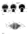
- FIG. 3 shows three different preferred Embodiments for a bridge. Shown are each in plan view of the cylindrical Skulltiegel 1 with glass outlet 1.5 and a preferred variant of the bridge 2.
- the bridge 2 may be a straight (Figure 3a), square ( Figure 3b) or curved ( Figure 3c) have cross-section.
- the bridge needs 2 also like the entire crucible wall 1.1 cooled from, preferably be constructed of metallic components.
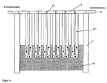
- the bridge 2 preferably, as shown in Figure 4, from individual, arranged meandering with respect to the coolant guide Tubes 2.2 built up, which are still at their upper ends electrically conductively connected to each other.
- an electrical contact metal connection
- the crucible 1 and the bridge 2 can in preferred Embodiments of the invention made of stainless steel, platinum, copper or aluminum. Which metal is suitably used, depends on the Composition of the glass to be melted and the Requirements for its purity.
- Stainless steel or copper skull crucibles can do that Corrosion resistance of the crucible material also by Applying a coating of a high temperature resistant Plastic whose decomposition temperature is below the Temperature of the coating in the contact area Coating / melt is to be improved.
- Plastic materials come, for example, high-fluorine Plastics, in particular PTFE, in question.
- Such Coating has the further advantage of being exposed Parts of the crucible from attacking by evaporating Components are protected from the molten glass.
- the fat The coating should be sized so that the cooling through the metal pipes still sufficient, the contact temperature between coating and melt below the To maintain decomposition temperature of the plastic.
- a Coating with plastic has the further advantage that adhesion of the glass to the coated parts not takes place and that the flashover between the metallic Skullrohren is reduced. It is the same possible, a crucible of a little corrosion resistant Metal with a metal with higher corrosion resistance to coat.
- the spout 1.5 through the bent in the upper crucible area by 90 ° chilled tubes of skull crucible formed.
- These pipes are, as shown in Figure 5, at its end electrically conductively connected, so that too Outlet area has a short ring I, the the Spout 1.5 itself and the bridge 2 with encloses.
- outlets For crucibles, where a larger melting rate of a Glass (> 200 ml / min), several (two to four) outlets may be provided.
- An embodiment with two outlets 1.5.1 / 1.5.2 are shown in Figure 6.
- Outlets 1.5.1 and 1.5.2 are in this embodiment diametrically opposite (180 ° distance).
- a crucible with several outlets has the advantage that at one complicated hot forming, the only small glass throughputs can handle, possibly two lines with a crucible can be operated. This option is special interesting, if the glass after the Einschmelzteil no Purification needed more, since in this case only a second Shaping is necessary and no costly (because of Pt) Pt-fining chamber.
- the melting temperature can be increased almost arbitrarily, because there are no wall contact materials as limiting sizes available. In addition, it has a particularly noticeable effect on glass melts With high viscosity, a stirring by bubbling low on the Abschmelz intricate.
- a bubbling can in a skull crucible (1) either through at least one from above inserted bubbling tube or, as in Figure 1 represented by positioned in the bottom of the crucible 1.2 Bubbling nozzles 1.6 done.
- a further acceleration of the Abschmelz intricate can by Use of additional top heat in the area of Gemengeauflage be achieved.
- a burner 3 or else a used electrical direct or indirect heating become.
- the disclosure is hereby fully incorporated, train.
- the temperature of the melt increases in the range of Collar off to the outside.
- the glass melt can in the Edge of the collar to be cooled so far on this edge as a continuation of the crucible wall in the upper Crucible area a ring of refractory material placed can be.
- the cooled Metal tubes on the side facing the melt completely covered with molten glass and thus against the corrosive effect of the burner exhaust gases or the Evaporation products protected from the melt. In return prevents the glass melt on the cooled pipes that the upper furnace space too much cooled by the crucible tubes becomes.
- a further preferred embodiment of the invention becomes in the overflow or outlet area additionally upper heat used to prevent excessive cooling of the melt prevent this area and the glass flow sure.
- upper heat used to prevent excessive cooling of the melt prevent this area and the glass flow sure.
- the top heat can, as shown in Figure 1, means Burner 4 are generated.
- a bridge 2 before each spout 1.5 connected is a bridge 2 before each spout 1.5 connected.
- These bridges 2 are expediently so designed that the area of all "dead" areas 10.3 together as small as possible to the High-frequency entry into the largest possible melt volume and thus the highest possible melting rate of the mixture guarantee. But it is also easy Embodiments conceivable in which a continuous bridge is intended for multiple spouts.
- FIG. 7a shows a refractory crucible 1 according to the invention in combination with a platinum refining 5 and Homogenizing unit 6.
- a platinum refining 5 and Homogenizing unit 6 Such an arrangement can For example, as a continuous melting tank for aggressive, high purity glasses are used.
- Platinläuterhunt 5 can be different ways of glass transition between Sealing crucible 1 and Platinläuterhunt 5 conceivable. So can the Platinläuterhunt 5, for example, directly to the metallic short-circuit ring at the outer end of the glass spout 1.5 of the crucible 1 are flanged.
- the melt in the form of a glass strand free into the platinum annealing chamber 5 and there is no direct Connection between the crucible 1 and the subsequent refining chamber 5 and the Homogenizing device 6.
- the drop height of the glass can here, as in contrast to the known device, no Coil turns in the way are so small that the impact of bubbles and the formation of streaks to keep within tolerable limits.
- the effective melt volume in the crucible was approx. 25 l. It was a cooled bridge according to the in Figure 4 and Figure 3a used embodiment shown.
- the immersion depth the bridge in the melt was at a glass level in the Glass spout of approx. 30 mm approx. 50 mm, d. H. the lower edge
- the bridge was about 20 mm below the bottom of the Glass spout. This ensured that no undissolved mixtures under the bridge through to the Glass outlet could flow.
- the glass was added at an RF frequency of 386 kHz Generator power of approx. 250 kW melted. additionally was the melting in the meltdown by a Burner and bubbling with oxygen supported.
- the Molten glass was according to the invention above the Induction coil assembly withdrawn and, without the Go through coil area, further processing fed. This was realized by the fact that the bottom of the Glass spout 30 mm above the top of the Induction coil arrangement was. Furthermore, the outer protruded End of the glass outlet about 70 mm over the outer coil radius out.
- the smelting performance of the smelting unit was at the mentioned melt volume of 25 l between 0.5 and 2 t Glass / day and was thus significantly higher than at the beginning mentioned conventional melting process (1.0 t glass / day at a melt volume of 90 l).
Landscapes
- Chemical & Material Sciences (AREA)
- Engineering & Computer Science (AREA)
- Materials Engineering (AREA)
- Organic Chemistry (AREA)
- Glass Melting And Manufacturing (AREA)
- Crucibles And Fluidized-Bed Furnaces (AREA)
- General Induction Heating (AREA)
- Furnace Details (AREA)
Description
- Figur 1
- in schematischer Darstellung in einem Vertikalschnitt einen Einschmelztiegel gemäß der Erfindung (mit Darstellung der Konvektionswalzen und der heißen Kernzone);
- Figuren 2a und b
- zwei verschiedene Ausführungsformen für die Bodenplatte eines Skulltiegels;
- Figuren 3a,b,c
- in schematischer Darstellung in Draufsicht drei bevorzugte Ausführungsformen für die Ausführung und Anordnung der gekühlten Brücke gemäß der Erfindung;
- Figur 4
- in schematischer Darstellung in einem Vertikalschnitt eine gekühlte Brücke in einer bevorzugten Ausführungsform;
- Figur 5a,b
- in schematischer Darstellung in Vorder- und Seitenansicht die Anordnung der elektrischen Kurzschlussverbindungen im Auslaufbereich;
- Figur 6
- in schematischer Darstellung in Draufsicht von oben ein Einschmelztiegel gemäß der Erfindung mit zwei Ausläufen;
- Figur 7a
- in schematischer Darstellung in Seitenansicht eine Wanne mit direkter Verbindung zwischen HF-Einschmelztiegel und Platinrinne zur kontinuierlichen Prozeßführung;
- Figur 7b
- in schematischer Darstellung in Seitenansicht eine Wanne mit freifallendem Glasstrang zwischen dem HF-Einschmelztiegel und der Platinrinne.
mit der Zusammensetzung SiO2=65,0 Gew.-%; Al2O3=22,0 Gew.-%; Li2O=3,75 Gew.-%; Na2O=0,5 Gew.-%; BaO=2,0 Gew.-%; MgO=0,5 Gew.-%; TiO2=2,5 Gew.-%; ZnO=1,75 Gew.-%; ZrO2=1,7 Gew.-% und V2O5=0,3 Gew.-% geschmolzen.
Claims (26)
- Verfahren zum schnellen Einschmelzen insbesondere hochreiner, aggressiver und/oder hochschmelzender Gläser in einem Skulltiegel,
bei welchem zur Beheizung der Schmelze mittels einer den Skulltiegel umgebenden Spulenanordnung Hochfrequenzenergie in den Tiegelinhalt eingekoppelt wird,
und das Auflegen des Gemenges und das Abführen des aufgeschmolzenen Glases im oberen Tiegelbereich erfolgen,
und unaufgelöste Gemengebestandteile mittels einer gekühlten Brücke, die in die Schmelze eintaucht, zurückgehalten werden,
dadurch gekennzeichnet, dass das Glas oberhalb der Spulenanordnung (1.3) abgezogen und ohne den Spulenbereich zu durchströmen der Weiterverarbeitung zugeführt wird und
eine aus an ihren oberen Enden elektrisch leitend miteinander verbundenen Rohren (2.2) aufgebaute Brücke verwendet wird. - Verfahren nach Anspruch 1,
dadurch gekennzeichnet, dass das Glas in einem kontinuierlichen Prozess aus dem Glasauslauf (1.5) ausströmt in ein fest mit dem Glasauslauf (1.5) verbundenes Bauteil der nachfolgenden Verarbeitungsstufe. - Verfahren nach Anspruch 1,
dadurch gekennzeichnet, dass das Glas am Glasauslauf (1.5) überströmt und in Form eines Glasstrangs nach unten fällt. - Verfahren nach wenigstens einem der Ansprüche 1 bis 3,
dadurch gekennzeichnet, dass die Glasschmelze während des Aufschmelzens gerührt wird. - Verfahren nach wenigstens einem der Ansprüche 1 bis 4,
dadurch gekennzeichnet, dass die Glasschmelze über mehrere Ausläufe (1.5.1, 1.5.2) abgezogen wird. - Verfahren nach wenigstens einem der Ansprüche 1 bis 5
dadurch gekennzeichnet, dass im Gemengebereich und/oder im Überlauf bzw. Auslaufbereich zusätzlich Oberhitze zum Aufheizen der Glasschmelze eingesetzt wird. - Verfahren nach wenigstens einem der Ansprüche 1 bis 6,
dadurch gekennzeichnet, dass das Glas im Anschluss an das Einschmelzen geläutert und homogenisiert oder aber direkt einer Formgebungseinheit zugeführt wird. - Vorrichtung zum schnellen Einschmelzen insbesondere hochreiner, aggressiver und/oder hochschmelzender Gläser mit
einem Skulltiegel, der von einer Mehrzahl von gekühlten Metallrohren gebildet wird, die in gegenseitigen Abständen angeordnet sind,
einer den Skulltiegel umgebenden Spulenanordnung zum Einkoppeln von Hochfrequenzenergie in den Tiegelinhalt, Einrichtungen zum Auflegen von Gemenge und zum Abführen des aufgeschmolzenen Glases, die im oberen Tiegelbereich angeordnet sind,
und einer gekühlten Brücke, die in die Schmelze eintaucht und das Gemenge von der Einrichtung zum Abführen des Glases trennt,
dadurch gekennzeichnet, dass die Einrichtung zum Abführen des geschmolzenen Glases ein Glasauslauf (1.5) ist, der oberhalb der Spulenanordnung (1.3) angeordnet ist und dessen äußeres Ende über den Außenradius der Induktionsspule (1.3) hinausragt und
die Brücke aus Rohren (2.2) aufgebaut ist, die an ihren oberen Enden elektrisch leitend miteinander verbunden sind. - Vorrichtung nach Anspruch 8,
dadurch gekennzeichnet, dass der Glasauslauf (1.5) durch die im Auslaufbereich um vorzugsweise 90° nach außen hin abgeknickten gekühlten Rohre des Skulltiegels (1) gebildet wird, wobei die Rohrenden über den äußeren Radius der Spulenanordnung (1.3) hinausragen. - Vorrichtung nach Anspruch 9,
dadurch gekennzeichnet, dass die Rohrenden des Glasauslaufs (1.5) um wenigstens 2 cm über den äußeren Radius der Spulenanordnung (1.3) hinausragen. - Vorrichtung nach wenigstens einem der Ansprüche 8 bis 10,
dadurch gekennzeichnet, dass der Boden des Glasauslaufs (1.5) wenigstens 2 cm oberhalb des oberen Endes der Spulenanordnung (1.3) liegt. - Vorrichtung nach wenigstens einem der Ansprüche 8 bis 11,
dadurch gekennzeichnet, dass die Brücke (2) wenigstens 1 cm tief in die Schmelze eingetaucht ist. - Vorrichtung nach wenigstens einem der Ansprüche 8 bis 12,
dadurch gekennzeichnet, dass die Brücke (2) so angeordnet ist, dass ihr unteres Ende bis ca. 1 - 2 cm unterhalb des Bodens des Glasauslaufs (1.5) in den Skulltiegel (1) hineinragt. - Vorrichtung nach wenigstens einem der Ansprüche 8 bis 13,
dadurch gekennzeichnet, dass die Brücke (2) aus vertikal nebeneinander angeordneten gekühlten Rohren (2.1) besteht, die an ihren oberen und unteren Enden so miteinander verbunden sind, dass der Kühlmittelfluss durch die Rohre (2.1) mäanderförmig ist. - Vorrichtung nach wenigstens einem der Ansprüche 8 bis 14,
dadurch gekennzeichnet, dass die Brücke (2) in Draufsicht von oben geradlinig, rund oder eckig ausgebildet ist. - Vorrichtung nach wenigstens einem der Ansprüche 8 bis 15,
dadurch gekennzeichnet, dass der Skulltiegel (1) mehrere Glasausläufe (1.5) besitzt, wobei entweder jedem Auslauf (1.5) jeweils eine Brücke (2) zugeordnet ist oder aber eine einzige gemeinsame Brücke (2) den gesamten Auslaufbereich mit den mehreren Ausläufen (1.5) vom Gemengebereich abtrennt. - Vorrichtung nach Anspruch wenigstens einem der Ansprüche 8 bis 16,
dadurch gekennzeichnet, dass die Rohre des Skulltiegels (1) und der Brücke (2) aus Metall bestehen. - Vorrichtung nach Anspruch 17,
dadurch gekennzeichnet, dass die Metallrohre des Glasauslaufs (1.5) an ihren äußeren Enden mit einem Kurzschlussring versehen sind. - Vorrichtung nach wenigstens einem der Ansprüche 17 und 18,
dadurch gekennzeichnet,
und dass zwischen Glasauslauf (1.5) und Brücke (2) eine elektrisch leitende Verbindung besteht. - Vorrichtung nach wenigstens einem der Ansprüche 17 bis 19,
dadurch gekennzeichnet, dass die den Glasauslauf (1.5) bildenden abgeknickten Rohre des Skulltiegels (1) unterhalb des Knicks untereinander und mit den jeweils ersten dem Glasauslauf (1.5) benachbarten, nicht abgeknickten, nach oben geführten Rohren des Skulltiegels kurzgeschlossen sind. - Vorrichtung nach wenigstens einem der Ansprüche 8 bis 20,
dadurch gekennzeichnet, dass als Rühreinrichtung wenigstens ein von oben in den Skulltiegel (1) eingesetztes Bubblingrohr und/oder am Tiegelboden (1.2) angeordnete Bubblingdüsen (1.6) vorgesehen sind. - Vorrichtung nach wenigstens einem der Ansprüche 8 bis 21,
dadurch gekennzeichnet, dass im Oberofenraum im Gemengebereich und/oder im Überlauf bzw. Auslaufbereich Einrichtungen zur Erzeugung von Oberhitze vorgesehen sind. - Vorrichtung nach Anspruch 22,
dadurch gekennzeichnet, dass diese Einrichtungen Gasbrenner (3,4) sind. - Vorrichtung nach Anspruch 22 oder 23,
dadurch gekennzeichnet, dass der Skulltiegel (1) als Pilztiegel ausgebildet ist. - Vorrichtung nach wenigstens einem der Ansprüche 8 bis 24,
dadurch gekennzeichnet, dass dem Einschmelztiegel (1) eine Läuter- (5) und eine Homogenisierungseinheit (6) oder direkt eine Formgebungseinheit nachgeschaltet ist. - Vorrichtung nach Anspruch 25,
dadurch gekennzeichnet, dass die Läutereinheit (5) und/oder Homogenisierungseinheit (6) als hochfrequenzbeheizte Skull-Rinne oder hochfrequenzbeheizter Skull-Tiegel ausgebildet sind.
Applications Claiming Priority (3)
| Application Number | Priority Date | Filing Date | Title |
|---|---|---|---|
| DE10148754 | 2001-10-02 | ||
| DE10148754 | 2001-10-02 | ||
| PCT/EP2002/011006 WO2003031355A1 (de) | 2001-10-02 | 2002-10-01 | Verfahren und vorrichtung zum schmelzen von glas mittels einem induktionsbeheizten skulltiegel |
Publications (2)
| Publication Number | Publication Date |
|---|---|
| EP1432654A1 EP1432654A1 (de) | 2004-06-30 |
| EP1432654B1 true EP1432654B1 (de) | 2005-09-14 |
Family
ID=7701226
Family Applications (1)
| Application Number | Title | Priority Date | Filing Date |
|---|---|---|---|
| EP02785144A Expired - Lifetime EP1432654B1 (de) | 2001-10-02 | 2002-10-01 | Verfahren und vorrichtung zum schmelzen von glas mittels einem induktionsbeheizten skulltiegel |
Country Status (8)
| Country | Link |
|---|---|
| US (1) | US7444837B2 (de) |
| EP (1) | EP1432654B1 (de) |
| JP (1) | JP4392243B2 (de) |
| CN (1) | CN1291929C (de) |
| AT (1) | ATE304516T1 (de) |
| AU (1) | AU2002350474A1 (de) |
| DE (2) | DE10244807B4 (de) |
| WO (1) | WO2003031355A1 (de) |
Families Citing this family (16)
| Publication number | Priority date | Publication date | Assignee | Title |
|---|---|---|---|---|
| DE19939782C1 (de) * | 1999-08-21 | 2001-05-17 | Schott Glas | Vorrichtung und Verfahren zum Erschmelzen oder Läutern von Gläsern oder Glaskeramiken |
| DE10329718B4 (de) * | 2003-07-02 | 2006-04-27 | Schott Ag | Verfahren und Vorrichtung zum Einschmelzen von anorganischen Substanzen, insbesondere von Gläsern |
| DE102004011218B4 (de) * | 2004-03-04 | 2006-01-19 | Schott Ag | Röntgenopakes Glas, Verfahren zu seiner Herstellung und seine Verwendung |
| DE102005054319B4 (de) * | 2005-11-11 | 2013-04-25 | Schott Ag | Modularer Skulltiegel, Begrenzungs- und Erweiterungselemente und Verfahren zum Schmelzen und/oder Läutern einer anorganischen Substanz, insbesondere von Glas |
| DE102006004637B4 (de) * | 2006-01-31 | 2010-01-07 | Schott Ag | Induktiv beheizbarer Skulltiegel, Schmelzanlage und Verfahren zum kontinuierlichen Herstellen einer Glasschmelze |
| DE102007008299B4 (de) * | 2006-08-12 | 2012-06-14 | Schott Ag | Verfahren zur Herstellung von Gläsern, wobei die chemische Reduktion von Bestandteilen vermieden wird |
| DE102008004740A1 (de) | 2008-01-16 | 2009-09-17 | Schott Ag | Verfahren und Vorrichtung zur Herstellung von Glasprodukten aus einer Glasschmelze |
| DE102008004739A1 (de) | 2008-01-16 | 2009-07-23 | Schott Ag | Verfahren und Vorrichtung zum Schmelzen oder Läutern von Glasschmelzen |
| DE102009033502B4 (de) | 2009-07-15 | 2016-03-03 | Schott Ag | Verfahren und Vorrichtung zur Herstellung von Glasprodukten aus einer Glasschmelze |
| DE102009033500B4 (de) | 2009-07-15 | 2012-10-25 | Schott Ag | Verfahren und Vorrichtung mit Barriere zur kontinuierlichen Herstellung von Produkten aus einer Schmelze |
| DE102009033501B4 (de) * | 2009-07-15 | 2016-07-21 | Schott Ag | Verfahren und Vorrichtung zum kontinuierlichen Schmelzen oder Läutern von Schmelzen |
| DE102012209531B4 (de) | 2012-06-06 | 2017-03-30 | Schott Ag | Hochbrechendes Optisches Glas |
| US10604437B2 (en) * | 2014-10-20 | 2020-03-31 | Navus Automation, Inc. | Fused silica furnace system and method for continuous production of fused silica |
| CN106882916A (zh) * | 2017-02-22 | 2017-06-23 | 江西服装学院 | 玻璃3d打印方法及装置 |
| US10898949B2 (en) | 2017-05-05 | 2021-01-26 | Glassy Metals Llc | Techniques and apparatus for electromagnetically stirring a melt material |
| JP2025533855A (ja) * | 2022-10-04 | 2025-10-09 | コーニング インコーポレイテッド | 導管内の溶融ガラスを冷却するための装置及び方法 |
Family Cites Families (20)
| Publication number | Priority date | Publication date | Assignee | Title |
|---|---|---|---|---|
| US1538169A (en) * | 1924-04-07 | 1925-05-19 | Libbeyowens Sheet Glass Compan | Floater for glass furnaces |
| US1614114A (en) * | 1925-04-02 | 1927-01-11 | Libbey Owens Sheet Glass Co | Floater |
| GB627863A (en) | 1946-10-01 | 1949-08-17 | Walter Raymond Schlehr | Improvements in and relating to the conditioning of material, especially glass, for the drawing therefrom of fibres |
| BE794781A (fr) * | 1972-02-01 | 1973-07-31 | Ppg Industries Inc | Procede pour le faconnage de verre a haut point de fusion |
| GB1531742A (en) * | 1975-01-31 | 1978-11-08 | Pilkington Brothers Ltd | Manufacture of glass |
| FR2561761B1 (fr) * | 1984-03-20 | 1988-03-18 | Commissariat Energie Atomique | Dispositif d'evacuation en continu des produits fondus contenus dans un creuset froid |
| FR2589228B1 (fr) * | 1985-10-25 | 1989-08-04 | Commissariat Energie Atomique | Dispositif d'elaboration en continu de materiaux obtenus a partir de substances a l'etat fondu |
| FR2703041B1 (fr) * | 1993-03-23 | 1995-06-09 | Saint Gobain Vitrage Int | Procede et dispositif pour la fusion du verre. |
| DE19939786B8 (de) * | 1999-08-21 | 2004-07-08 | Schott Glas | Vorrichtung für das Erschmelzen oder das Läutern von Gläsern oder Glaskeramiken |
| DE19939771B4 (de) * | 1999-08-21 | 2004-04-15 | Schott Glas | Verfahren zur Läuterung von Glasschmelzen |
| DE19939782C1 (de) | 1999-08-21 | 2001-05-17 | Schott Glas | Vorrichtung und Verfahren zum Erschmelzen oder Läutern von Gläsern oder Glaskeramiken |
| DE19939773C2 (de) | 1999-08-21 | 2003-06-18 | Schott Glas | Vorrichtung und Verfahren für das Läutern von Gläsern oder Glaskeramiken |
| DE19939780C2 (de) * | 1999-08-21 | 2002-02-14 | Schott Glas | Skulltiegel für das Erschmelzen oder das Läutern von Gläsern oder Glaskeramiken |
| DE19939784C1 (de) * | 1999-08-21 | 2001-05-03 | Schott Glas | HF-Wall in einer technischen Wanne |
| DE19939779C2 (de) * | 1999-08-21 | 2003-06-26 | Schott Glas | Vorrichtung und Verfahren zum kontinuierlichen Erschmelzen und Läutern von anorganischen Verbindungen, insbesondere von Gläsern und Glaskeramiken |
| DE19939785C2 (de) * | 1999-08-21 | 2003-12-18 | Schott Glas | Verfahren und Vorrichtung zum Herstellen von farbigen Gläsern |
| DE19939772C1 (de) * | 1999-08-21 | 2001-05-03 | Schott Glas | Skulltiegel für das Erschmelzen oder das Läutern von Gläsern |
| DE10041757C1 (de) | 2000-08-25 | 2002-02-21 | Schott Glas | Verfahren und Vorrichtung zum Läutern von Glas |
| DE10138109A1 (de) | 2001-08-03 | 2002-09-12 | Schott Glas | Verfahren und Vorrichtung zum Herstellen von optischen Gläsern |
| US10049948B2 (en) * | 2012-11-30 | 2018-08-14 | Lam Research Corporation | Power switching system for ESC with array of thermal control elements |
-
2002
- 2002-09-26 DE DE10244807A patent/DE10244807B4/de not_active Expired - Fee Related
- 2002-10-01 AU AU2002350474A patent/AU2002350474A1/en not_active Abandoned
- 2002-10-01 WO PCT/EP2002/011006 patent/WO2003031355A1/de not_active Ceased
- 2002-10-01 DE DE50204288T patent/DE50204288D1/de not_active Expired - Lifetime
- 2002-10-01 US US10/490,909 patent/US7444837B2/en not_active Expired - Fee Related
- 2002-10-01 CN CNB028181808A patent/CN1291929C/zh not_active Expired - Lifetime
- 2002-10-01 AT AT02785144T patent/ATE304516T1/de not_active IP Right Cessation
- 2002-10-01 JP JP2003534345A patent/JP4392243B2/ja not_active Expired - Lifetime
- 2002-10-01 EP EP02785144A patent/EP1432654B1/de not_active Expired - Lifetime
Also Published As
| Publication number | Publication date |
|---|---|
| AU2002350474A1 (en) | 2003-04-22 |
| ATE304516T1 (de) | 2005-09-15 |
| JP2005504707A (ja) | 2005-02-17 |
| CN1291929C (zh) | 2006-12-27 |
| DE10244807B4 (de) | 2011-07-14 |
| JP4392243B2 (ja) | 2009-12-24 |
| DE10244807A1 (de) | 2003-07-10 |
| US20050039492A1 (en) | 2005-02-24 |
| CN1639075A (zh) | 2005-07-13 |
| US7444837B2 (en) | 2008-11-04 |
| WO2003031355A1 (de) | 2003-04-17 |
| DE50204288D1 (de) | 2005-10-20 |
| EP1432654A1 (de) | 2004-06-30 |
Similar Documents
| Publication | Publication Date | Title |
|---|---|---|
| DE10329718B4 (de) | Verfahren und Vorrichtung zum Einschmelzen von anorganischen Substanzen, insbesondere von Gläsern | |
| DE10041757C1 (de) | Verfahren und Vorrichtung zum Läutern von Glas | |
| DE102010048297B4 (de) | Vorrichtung zum Läutern einer anorganischen nichtmetallischen Schmelze und Verfahren zur Herstellung eines Glases und/oder einer Glaskeramik | |
| DE10244807B4 (de) | Verfahren und Vorrichtung zum schnellen Einschmelzen insbesondere hochreiner aggressiver und hochschmelzender Gläser | |
| EP1979277B1 (de) | Verfahren und vorrichtung zum läutern einer glasschmelze | |
| EP0317551B1 (de) | Glasschmelzofen | |
| DE19939773C2 (de) | Vorrichtung und Verfahren für das Läutern von Gläsern oder Glaskeramiken | |
| EP1206417B1 (de) | Skulltiegel für das erschmelzen oder das läutern von anorganischen substanzen | |
| EP1206420B1 (de) | Vorrichtung zum kontinuierlichen erschmelzen und läutern von anorganischen verbindungen, insbesondere von gläsern und glaskeramiken | |
| EP1434741A2 (de) | Vorrichtung und verfahren zum kontaminationsarmen schmelzen von glas oder glaskeramik | |
| EP1206419B1 (de) | Verfahren und vorrichtung zum herstellen von farbigen gläsern | |
| EP1250294B1 (de) | Vorrichtung zum erschmelzen oder läutern von anorganischen substanzen | |
| DE19939786C2 (de) | Vorrichtung für das Erschmelzen oder das Läutern von Gläsern oder Glaskeramiken | |
| DE102009021181A1 (de) | Vorrichtung und Verfahren zum Schmelzen und Läutern einer Glasschmelze | |
| DE19939784C1 (de) | HF-Wall in einer technischen Wanne | |
| EP1313671B1 (de) | Verfahren zum erzeugen einer homogenisierten glasschmelze | |
| DD226868A1 (de) | Ofen zum schmelzen und laeutern von silikatischen stoffen, insbesondere von glas | |
| DE10202024A1 (de) | Vorrichtung und Verfahren zum kontaminationsarmen Schmelzen einer Substanz | |
| WO2001077034A2 (de) | Vorrichtung zum herstellen einer glasschmelze | |
| DD141301A1 (de) | Verfahren und vorrichtung zum schmelzen und laeutern von glas |
Legal Events
| Date | Code | Title | Description |
|---|---|---|---|
| PUAI | Public reference made under article 153(3) epc to a published international application that has entered the european phase |
Free format text: ORIGINAL CODE: 0009012 |
|
| 17P | Request for examination filed |
Effective date: 20040124 |
|
| AK | Designated contracting states |
Kind code of ref document: A1 Designated state(s): AT BE BG CH CY CZ DE DK EE ES FI FR GB GR IE IT LI LU MC NL PT SE SK TR |
|
| AX | Request for extension of the european patent |
Extension state: AL LT LV MK RO SI |
|
| 17Q | First examination report despatched |
Effective date: 20040622 |
|
| RIN1 | Information on inventor provided before grant (corrected) |
Inventor name: NUETTGENS, SYBILLE Inventor name: OHMSTEDE, VOLKER Inventor name: SCHAEFER, ERNEST, WALTER Inventor name: LEISTER, MICHAEL Inventor name: RAEKE, GUIDO Inventor name: KOLBERG, UWE Inventor name: MENNEMANN, KARL Inventor name: ROEMER, HILDEGARD |
|
| RAP1 | Party data changed (applicant data changed or rights of an application transferred) |
Owner name: SCHOTT AG |
|
| GRAP | Despatch of communication of intention to grant a patent |
Free format text: ORIGINAL CODE: EPIDOSNIGR1 |
|
| GRAS | Grant fee paid |
Free format text: ORIGINAL CODE: EPIDOSNIGR3 |
|
| GRAA | (expected) grant |
Free format text: ORIGINAL CODE: 0009210 |
|
| AK | Designated contracting states |
Kind code of ref document: B1 Designated state(s): AT BE BG CH CY CZ DE DK EE ES FI FR GB GR IE IT LI LU MC NL PT SE SK TR |
|
| PG25 | Lapsed in a contracting state [announced via postgrant information from national office to epo] |
Ref country code: IT Free format text: LAPSE BECAUSE OF FAILURE TO SUBMIT A TRANSLATION OF THE DESCRIPTION OR TO PAY THE FEE WITHIN THE PRESCRIBED TIME-LIMIT;WARNING: LAPSES OF ITALIAN PATENTS WITH EFFECTIVE DATE BEFORE 2007 MAY HAVE OCCURRED AT ANY TIME BEFORE 2007. THE CORRECT EFFECTIVE DATE MAY BE DIFFERENT FROM THE ONE RECORDED. Effective date: 20050914 Ref country code: SK Free format text: LAPSE BECAUSE OF FAILURE TO SUBMIT A TRANSLATION OF THE DESCRIPTION OR TO PAY THE FEE WITHIN THE PRESCRIBED TIME-LIMIT Effective date: 20050914 Ref country code: EE Free format text: LAPSE BECAUSE OF FAILURE TO SUBMIT A TRANSLATION OF THE DESCRIPTION OR TO PAY THE FEE WITHIN THE PRESCRIBED TIME-LIMIT Effective date: 20050914 Ref country code: IE Free format text: LAPSE BECAUSE OF FAILURE TO SUBMIT A TRANSLATION OF THE DESCRIPTION OR TO PAY THE FEE WITHIN THE PRESCRIBED TIME-LIMIT Effective date: 20050914 Ref country code: NL Free format text: LAPSE BECAUSE OF FAILURE TO SUBMIT A TRANSLATION OF THE DESCRIPTION OR TO PAY THE FEE WITHIN THE PRESCRIBED TIME-LIMIT Effective date: 20050914 Ref country code: GB Free format text: LAPSE BECAUSE OF FAILURE TO SUBMIT A TRANSLATION OF THE DESCRIPTION OR TO PAY THE FEE WITHIN THE PRESCRIBED TIME-LIMIT Effective date: 20050914 Ref country code: FI Free format text: LAPSE BECAUSE OF FAILURE TO SUBMIT A TRANSLATION OF THE DESCRIPTION OR TO PAY THE FEE WITHIN THE PRESCRIBED TIME-LIMIT Effective date: 20050914 Ref country code: CZ Free format text: LAPSE BECAUSE OF FAILURE TO SUBMIT A TRANSLATION OF THE DESCRIPTION OR TO PAY THE FEE WITHIN THE PRESCRIBED TIME-LIMIT Effective date: 20050914 Ref country code: TR Free format text: LAPSE BECAUSE OF FAILURE TO SUBMIT A TRANSLATION OF THE DESCRIPTION OR TO PAY THE FEE WITHIN THE PRESCRIBED TIME-LIMIT Effective date: 20050914 |
|
| REG | Reference to a national code |
Ref country code: GB Ref legal event code: FG4D Free format text: NOT ENGLISH |
|
| REG | Reference to a national code |
Ref country code: CH Ref legal event code: EP Ref country code: CH Ref legal event code: NV Representative=s name: BOVARD AG PATENTANWAELTE |
|
| PG25 | Lapsed in a contracting state [announced via postgrant information from national office to epo] |
Ref country code: AT Free format text: LAPSE BECAUSE OF NON-PAYMENT OF DUE FEES Effective date: 20051001 Ref country code: CY Free format text: LAPSE BECAUSE OF FAILURE TO SUBMIT A TRANSLATION OF THE DESCRIPTION OR TO PAY THE FEE WITHIN THE PRESCRIBED TIME-LIMIT Effective date: 20051001 |
|
| REG | Reference to a national code |
Ref country code: IE Ref legal event code: FG4D Free format text: LANGUAGE OF EP DOCUMENT: GERMAN |
|
| REF | Corresponds to: |
Ref document number: 50204288 Country of ref document: DE Date of ref document: 20051020 Kind code of ref document: P |
|
| PG25 | Lapsed in a contracting state [announced via postgrant information from national office to epo] |
Ref country code: BE Free format text: LAPSE BECAUSE OF NON-PAYMENT OF DUE FEES Effective date: 20051031 Ref country code: MC Free format text: LAPSE BECAUSE OF NON-PAYMENT OF DUE FEES Effective date: 20051031 |
|
| PG25 | Lapsed in a contracting state [announced via postgrant information from national office to epo] |
Ref country code: LU Free format text: LAPSE BECAUSE OF NON-PAYMENT OF DUE FEES Effective date: 20051114 |
|
| PG25 | Lapsed in a contracting state [announced via postgrant information from national office to epo] |
Ref country code: DK Free format text: LAPSE BECAUSE OF FAILURE TO SUBMIT A TRANSLATION OF THE DESCRIPTION OR TO PAY THE FEE WITHIN THE PRESCRIBED TIME-LIMIT Effective date: 20051214 Ref country code: SE Free format text: LAPSE BECAUSE OF FAILURE TO SUBMIT A TRANSLATION OF THE DESCRIPTION OR TO PAY THE FEE WITHIN THE PRESCRIBED TIME-LIMIT Effective date: 20051214 Ref country code: BG Free format text: LAPSE BECAUSE OF FAILURE TO SUBMIT A TRANSLATION OF THE DESCRIPTION OR TO PAY THE FEE WITHIN THE PRESCRIBED TIME-LIMIT Effective date: 20051214 Ref country code: GR Free format text: LAPSE BECAUSE OF FAILURE TO SUBMIT A TRANSLATION OF THE DESCRIPTION OR TO PAY THE FEE WITHIN THE PRESCRIBED TIME-LIMIT Effective date: 20051214 |
|
| PG25 | Lapsed in a contracting state [announced via postgrant information from national office to epo] |
Ref country code: ES Free format text: LAPSE BECAUSE OF FAILURE TO SUBMIT A TRANSLATION OF THE DESCRIPTION OR TO PAY THE FEE WITHIN THE PRESCRIBED TIME-LIMIT Effective date: 20051225 |
|
| PG25 | Lapsed in a contracting state [announced via postgrant information from national office to epo] |
Ref country code: PT Free format text: LAPSE BECAUSE OF FAILURE TO SUBMIT A TRANSLATION OF THE DESCRIPTION OR TO PAY THE FEE WITHIN THE PRESCRIBED TIME-LIMIT Effective date: 20060214 |
|
| NLV1 | Nl: lapsed or annulled due to failure to fulfill the requirements of art. 29p and 29m of the patents act | ||
| GBV | Gb: ep patent (uk) treated as always having been void in accordance with gb section 77(7)/1977 [no translation filed] |
Effective date: 20050914 |
|
| ET | Fr: translation filed | ||
| REG | Reference to a national code |
Ref country code: IE Ref legal event code: FD4D |
|
| PLBE | No opposition filed within time limit |
Free format text: ORIGINAL CODE: 0009261 |
|
| STAA | Information on the status of an ep patent application or granted ep patent |
Free format text: STATUS: NO OPPOSITION FILED WITHIN TIME LIMIT |
|
| 26N | No opposition filed |
Effective date: 20060615 |
|
| BERE | Be: lapsed |
Owner name: SCHOTT A.G. Effective date: 20051031 |
|
| PGFP | Annual fee paid to national office [announced via postgrant information from national office to epo] |
Ref country code: CH Payment date: 20071015 Year of fee payment: 6 |
|
| PGFP | Annual fee paid to national office [announced via postgrant information from national office to epo] |
Ref country code: FR Payment date: 20071016 Year of fee payment: 6 |
|
| REG | Reference to a national code |
Ref country code: CH Ref legal event code: PL |
|
| REG | Reference to a national code |
Ref country code: FR Ref legal event code: ST Effective date: 20090630 |
|
| PG25 | Lapsed in a contracting state [announced via postgrant information from national office to epo] |
Ref country code: CH Free format text: LAPSE BECAUSE OF NON-PAYMENT OF DUE FEES Effective date: 20081031 Ref country code: LI Free format text: LAPSE BECAUSE OF NON-PAYMENT OF DUE FEES Effective date: 20081031 Ref country code: FR Free format text: LAPSE BECAUSE OF NON-PAYMENT OF DUE FEES Effective date: 20081031 |
|
| PGFP | Annual fee paid to national office [announced via postgrant information from national office to epo] |
Ref country code: DE Payment date: 20181019 Year of fee payment: 17 |
|
| REG | Reference to a national code |
Ref country code: DE Ref legal event code: R119 Ref document number: 50204288 Country of ref document: DE |
|
| PG25 | Lapsed in a contracting state [announced via postgrant information from national office to epo] |
Ref country code: DE Free format text: LAPSE BECAUSE OF NON-PAYMENT OF DUE FEES Effective date: 20200501 |