EP1432890B1 - Arbre a cames et procede de fabrication - Google Patents
Arbre a cames et procede de fabrication Download PDFInfo
- Publication number
- EP1432890B1 EP1432890B1 EP02758031A EP02758031A EP1432890B1 EP 1432890 B1 EP1432890 B1 EP 1432890B1 EP 02758031 A EP02758031 A EP 02758031A EP 02758031 A EP02758031 A EP 02758031A EP 1432890 B1 EP1432890 B1 EP 1432890B1
- Authority
- EP
- European Patent Office
- Prior art keywords
- shaft
- camshaft
- diameter
- ground
- cams
- Prior art date
- Legal status (The legal status is an assumption and is not a legal conclusion. Google has not performed a legal analysis and makes no representation as to the accuracy of the status listed.)
- Expired - Lifetime
Links
- 238000000034 method Methods 0.000 title claims description 18
- 238000004519 manufacturing process Methods 0.000 claims abstract description 18
- 239000002184 metal Substances 0.000 claims description 19
- 238000009434 installation Methods 0.000 claims description 2
- 239000000463 material Substances 0.000 description 5
- 230000006378 damage Effects 0.000 description 4
- 230000001105 regulatory effect Effects 0.000 description 4
- 238000003466 welding Methods 0.000 description 4
- 238000003825 pressing Methods 0.000 description 3
- 239000011343 solid material Substances 0.000 description 3
- 208000027418 Wounds and injury Diseases 0.000 description 2
- 230000001276 controlling effect Effects 0.000 description 2
- 208000014674 injury Diseases 0.000 description 2
- 238000005304 joining Methods 0.000 description 2
- 238000007493 shaping process Methods 0.000 description 2
- 238000003860 storage Methods 0.000 description 2
- 230000015572 biosynthetic process Effects 0.000 description 1
- 238000002485 combustion reaction Methods 0.000 description 1
- 239000002131 composite material Substances 0.000 description 1
- 238000010276 construction Methods 0.000 description 1
- 230000001419 dependent effect Effects 0.000 description 1
- 230000001050 lubricating effect Effects 0.000 description 1
- 239000007769 metal material Substances 0.000 description 1
- 238000012805 post-processing Methods 0.000 description 1
- 238000005096 rolling process Methods 0.000 description 1
- 238000006748 scratching Methods 0.000 description 1
- 230000002393 scratching effect Effects 0.000 description 1
- 230000007704 transition Effects 0.000 description 1
Images


Classifications
-
- F—MECHANICAL ENGINEERING; LIGHTING; HEATING; WEAPONS; BLASTING
- F01—MACHINES OR ENGINES IN GENERAL; ENGINE PLANTS IN GENERAL; STEAM ENGINES
- F01L—CYCLICALLY OPERATING VALVES FOR MACHINES OR ENGINES
- F01L1/00—Valve-gear or valve arrangements, e.g. lift-valve gear
- F01L1/02—Valve drive
- F01L1/04—Valve drive by means of cams, camshafts, cam discs, eccentrics or the like
- F01L1/047—Camshafts
-
- Y—GENERAL TAGGING OF NEW TECHNOLOGICAL DEVELOPMENTS; GENERAL TAGGING OF CROSS-SECTIONAL TECHNOLOGIES SPANNING OVER SEVERAL SECTIONS OF THE IPC; TECHNICAL SUBJECTS COVERED BY FORMER USPC CROSS-REFERENCE ART COLLECTIONS [XRACs] AND DIGESTS
- Y10—TECHNICAL SUBJECTS COVERED BY FORMER USPC
- Y10T—TECHNICAL SUBJECTS COVERED BY FORMER US CLASSIFICATION
- Y10T74/00—Machine element or mechanism
- Y10T74/21—Elements
- Y10T74/2101—Cams
Definitions
- the invention relates to a camshaft for receiving cams according to the preamble of claim 1 and to a method for producing a camshaft for mounting cams according to the preamble of claim 4.
- Camshafts of this type are used for controlling machine parts, in particular for controlling parts in internal combustion engines, such as for valves.
- composite camshafts also referred to as built camshafts
- control cams are mounted on the camshaft and fastened in the space provided, for example by welding or pressing with the shaft.
- the control shaft can consist of solid material as well as of tube material.
- solid material cams can also be made of sheet metal, for example by sheet metal forming, as disclosed in the published patent applications DE 196 40 872 .
- DE 100 24 553 and the patent US 5,201,246 has become known, for example.
- the object of the invention is to eliminate the disadvantages of the prior art.
- the object is to realize a camshaft with a suitable manufacturing method, which makes it possible to produce bearings with consistently high quality and this with high efficiency.
- the object is achieved according to the invention in that the camshaft is ground prior to the camshaft assembly in the area of future bearings in such a way that the sensitive bearings have a smaller diameter than the main diameter of the shaft.
- the bearings are here advantageously simultaneously, ie with a single operation, ground. This allows a particularly economical production with good and consistent quality.
- a further advantageous simplification results when the shaft is formed as a tube. This can further save weight and material.
- the procedure according to the invention drastically reduces the risk of damage to the bearing points during the assembly of the cams.
- these can, as their opening corresponds to the larger shaft diameter, be passed over this without damaging the bearings and attached to the designated location.
- Another advantage is that the grinding time is shortened because the required dimensional accuracy for the grinding is lower for the axial position of the bearing. Furthermore, the previously additional punctures are no longer required side of the bearing to be provided.
- camshaft and method are suitable for all types of cam in an advantageous manner.
- the use of cams made of sheet metal material is particularly suitable, since a large weight saving is possible thereby and a particularly economical production of the camshaft as a whole can be achieved.
- the production of the metal cam from a profile profiled in cam bar profile, which is cut to length in the width of the cam to be created and is then joined, for example, by welding or pressing on the shaft at the designated location.
- the inventive method now offers further advantages.
- the shaft can be held in one or more storage areas during the grinding operation. This increases the precision of the cam contour and reduces the susceptibility to errors.
- only the cam contours and thrust bearing surfaces and possibly special surfaces, such as cones have to be ground for receiving pulleys. In the overall process thereby the grinding time is shortened and the grinding process more robust.
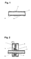
- a camshaft 5 is shown for receiving cams and for receiving camshaft bearing, which is ground at least in some areas according to the invention on the shaft surface to a certain diameter diameter.
- the camshaft 5 is advantageously tubular in shape to save material and weight.
- the surface of this shaft 5 is ground at least in areas where the shaft 5 is to be stored in the future at the so-called bearings 51 and ground to a smaller diameter compared to the original shaft diameter or the larger shaft diameter.
- the ground smaller diameter of the shaft 5 is compared to the shaft diameter by a few hundredths to a few tenths mm be smaller. As a result, can be drawn up on the shaft 5 cams 6 without injury to the sensitive bearings 51 and fasten it to the designated location 7 on the shaft 5.
- the shaft 5 is thus ground before the camshaft assembly.
- the future bearings 51 are all ground simultaneously so that the sensitive bearing 51 has a slightly thinner diameter, whereby the risk of damage in the subsequent assembly of the cam 6 is reduced.
- Another advantage is that the grinding time can be shortened and the required dimensional accuracy in the axial direction for positioning of the bearings is reduced.
- the often customary additional recesses on the side of the bearing to be arranged in the shaft 5 are no longer required by the inventive procedure.
- cam 6 is used for camshafts produced in this way, which cam is designed as a sheet metal construction, as shown in cross section in FIG.
- Such metal cams are formed, for example, in cross-section T-shaped and are advantageously connected to a first angular sheet metal part 1 and a second angular sheet metal part 2 together to form a T-shaped cam part, which has a precise running surface on the outside, on demand also on Mass and can be ground according to the desired curve shape.
- Such sheet metal parts can be produced in a simple manner in mass production, for example as pressed sheet metal half shells.
- positioning means 11 may be provided on the sheet metal parts 1, 2, which, for example can be produced as a nub or dent by pressing in the sheet metal parts.
- the sheet metal parts 1, 2 additionally have an opening corresponding to the shaft 5, which make it possible to raise the cam 6 formed therefrom onto the shaft.
- a sleeve 3 is pressed between the sheet metal cam 6 and the shaft 5.
- the sleeve 3 is made of softer material and the sheet metal parts 1, 2 of the metal cam 6 made of curable material.
- a roller 7 is provided in the region of the cam set position on the shaft 5, which produces a slight excess in this area relative to the shaft diameter.
- cams which are made of solid material.
- metal cams 6 is far more preferred in this regard, on the one hand for reasons of weight on the other hand for cost reasons, and in combination with the inventive ground shaft, it is possible to place the bearings extremely close to the cam 6, because as shown in Fig. 2, the bearings 51st can even be ground so that bearings can be brought close to the mounted cam 6 or even easily undercut the outer contour of the cam 6, as shown by the distance designation d in Fig. 2.
- the inventive grinding of the bearings 51 on the camshaft 5 no additional puncturing operations for positioning and delimitation of the bearings necessary, as is common in the prior art.
- the corresponding shaping of the end regions of the ground bearing points 51 can be predetermined.
- the original diameter of the shaft 5 is designated RD and the ground bearing diameter with LD.
- LB denotes the bearing width and SB the disc outlet width. Due to the bevel in the edge region of the bearing width LB, tilting when mounting the cams 6 can additionally be prevented.
- the procedure may be as follows.
- the shaft 5 is ground by a wide grinding roller SW1 and a regulating wheel SW2 over its entire length to its outer diameter RD, as shown in FIG. 4 in longitudinal section.
- Regulating wheels are used in grinding arrangements for positioning the grinding wheels or for adjusting the grinding mass (see Dubbel, page T93, Figure 49).
- the shaft 5 is ground to the desired reduced Lager gutmessermass LD, as shown in Fig. 5 is.
- the discs can be formed in the edge region according to the desired outlet shape, for example for a Transition from diameter LD to RD, which is formed obliquely.
- a further preferred variant with a wide profiled grinding wheel SW1 and a wide profiled regulating wheel SW2 is shown in section. This solution allows the simultaneous plunge grinding of bearings and the grinding of the shaft diameter RD together.
- a further preferred embodiment of the inventive method is that between the bearings 51 and the cam set position 7, the shaft remains unground with its outer diameter RD.
- the shaft remains unground with its outer diameter RD.
- sets of grinding wheels S1 and regulating wheel sets S2, which are alternately arranged at such a distance that at the correspondingly desired positions on the shaft recordings A for mounting bearings L for producing the bearing points 51 and cam set positions N can be ground.
- the procedure here is very efficient, since the entire grinding process can be performed simultaneously, wherein the bearings 51 are ground according to the invention to the smallest shaft diameter.
Landscapes
- Engineering & Computer Science (AREA)
- Mechanical Engineering (AREA)
- General Engineering & Computer Science (AREA)
- Valve-Gear Or Valve Arrangements (AREA)
Claims (9)
- Arbre à cames prévu pour recevoir des cames (6) et pour recevoir des paliers d'arbre à cames, qui est rectifié à une dimension déterminée de diamètre sur la surface d'enveloppe de l'arbre, au moins dans des zones partielles, caractérisé en ce que l'arbre (5) est rectifié, dans des zones des positions prévues (51) de paliers, à un diamètre plus petit (LD) que le diamètre plus grand (RD) d'arbre.
- Arbre à cames selon la revendication 1, caractérisé en ce que le diamètre rectifié plus petit (LD) de l'arbre (5) est plus petit, de quelques centièmes à quelques dixièmes de mm, que le diamètre (RD) d'arbre.
- Arbre à cames selon la revendication 1 ou 2, caractérisé en ce que l'arbre (5) est de structure tubulaire.
- Procédé de fabrication d'un arbre à cames (5) prévu pour le montage de cames (6) et comportant des positions (51) de palier, caractérisé en ce que les positions (51) de palier sont rectifiées à un diamètre plus petit (LD) que le diamètre (RD) d'arbre et en ce que les cames (6) sont ensuite glissées, lors de leur montage, à leur emplacement prévu à cet effet sur l'arbre (5) à diamètre plus grand (RD) d'arbre, sans se coincer sur les positions (51) de palier et sans endommager celles-ci.
- Procédé de fabrication d'un arbre à cames selon la revendication 4, caractérisé en ce que le processus de rectification s'effectue simultanément pour plusieurs emplacements (51) de paliers, et en particulier simultanément avec une rectification additionnelle de la surface de l'arbre, dans la mesure où celle-ci est prévue.
- Procédé de fabrication d'un arbre à cames selon la revendication 4 ou 5, caractérisé en ce que les cames (6) consistent en pièces de tôle (1, 2, 3)
- Procédé de fabrication d'un arbre à cames selon l'une quelconque des revendications 4 à 6, caractérisé en ce que les cames (6) sont fabriquées à partir d'un profilé de forme tubulaire.
- Procédé de fabrication d'un arbre à cames selon l'une quelconque des revendications 4 à 7, caractérisé en ce que l'arbre à cames (5) est de structure tubulaire.
- Procédé de fabrication d'un arbre à cames selon l'une quelconque des revendications 4 à 8, caractérisé en ce que le diamètre (LD) de la position rectifiée (51) de palier est plus petite, de quelques centièmes à quelques dixièmes de mm, que le diamètre plus grand (RD) de l'arbre.
Applications Claiming Priority (3)
| Application Number | Priority Date | Filing Date | Title |
|---|---|---|---|
| CH178001 | 2001-09-27 | ||
| CH17802001 | 2001-09-27 | ||
| PCT/CH2002/000491 WO2003027446A1 (fr) | 2001-09-27 | 2002-09-09 | Arbre a cames et procede de fabrication |
Publications (2)
| Publication Number | Publication Date |
|---|---|
| EP1432890A1 EP1432890A1 (fr) | 2004-06-30 |
| EP1432890B1 true EP1432890B1 (fr) | 2007-07-25 |
Family
ID=4566250
Family Applications (1)
| Application Number | Title | Priority Date | Filing Date |
|---|---|---|---|
| EP02758031A Expired - Lifetime EP1432890B1 (fr) | 2001-09-27 | 2002-09-09 | Arbre a cames et procede de fabrication |
Country Status (6)
| Country | Link |
|---|---|
| US (1) | US20040244528A1 (fr) |
| EP (1) | EP1432890B1 (fr) |
| AT (1) | ATE368174T1 (fr) |
| DE (1) | DE50210565D1 (fr) |
| ES (1) | ES2288557T3 (fr) |
| WO (1) | WO2003027446A1 (fr) |
Cited By (1)
| Publication number | Priority date | Publication date | Assignee | Title |
|---|---|---|---|---|
| DE102013210403A1 (de) | 2013-06-05 | 2014-12-11 | Mahle International Gmbh | Verfahren zur Herstellung einer Nockenwelle |
Families Citing this family (4)
| Publication number | Priority date | Publication date | Assignee | Title |
|---|---|---|---|---|
| DE10219195C1 (de) * | 2002-04-29 | 2003-11-27 | Thyssen Krupp Automotive Ag | Einstückig ausgebildeter Nocken |
| DE102007013039A1 (de) | 2007-03-19 | 2008-09-25 | Schaeffler Kg | Verfahren der Anordnung eines ungeteilten Wälzlagers an einer Welle und Wälzlager dafür |
| US8887682B2 (en) * | 2012-12-11 | 2014-11-18 | Mahle International Gmbh | Low friction camshaft |
| DE102014106924A1 (de) | 2014-05-16 | 2015-11-19 | Thyssenkrupp Presta Teccenter Ag | Verfahren zur Herstellung einer gebauten Nockenwelle |
Family Cites Families (26)
| Publication number | Priority date | Publication date | Assignee | Title |
|---|---|---|---|---|
| US1984936A (en) * | 1932-12-01 | 1934-12-18 | Norton Co | Grinding wheel |
| US2284606A (en) * | 1939-10-13 | 1942-05-26 | Norton Co | Camshaft bearing grinding machine |
| US4419845A (en) * | 1980-03-25 | 1983-12-13 | Ernst Thielenhaus Kg | Method of and apparatus for finish-grinding a camshaft |
| JPS61290271A (ja) * | 1985-06-18 | 1986-12-20 | Nippon Piston Ring Co Ltd | 中空カムシヤフト |
| DE3536296C1 (de) * | 1985-10-11 | 1987-03-26 | Supervis Ets | Nockenwelle |
| DE8626272U1 (de) * | 1986-10-01 | 2000-08-17 | Emitec Gesellschaft für Emissionstechnologie mbH, 53797 Lohmar | Gebaute Nockenwelle aus einem Wellenrohr und aufgeschobenen Elementen |
| DE3717190A1 (de) * | 1987-05-22 | 1988-12-15 | Supervis Ets | Nockenwelle zur steuerung von ventilen bei verbrennungskraftmaschinen und verfahren zu ihrer herstellung |
| DE3740597A1 (de) * | 1987-11-30 | 1989-06-08 | Grieshaber Masch | Flexible mehrstationige maschine zur bearbeitung von rotationssymmetrischen oberflaechen |
| JP3163505B2 (ja) * | 1991-06-07 | 2001-05-08 | 日本ピストンリング株式会社 | シャフトを嵌合部材に圧入してなる機械要素及びその製造方法 |
| DE4121951C1 (fr) * | 1991-07-03 | 1992-12-24 | Supervis Ets | |
| US5280675A (en) * | 1992-07-13 | 1994-01-25 | The Torrington Company | Camshaft and method of making a camshaft |
| US5201246A (en) | 1992-07-20 | 1993-04-13 | General Motors Corporation | Lightweight composite camshaft |
| US5371973A (en) * | 1992-09-30 | 1994-12-13 | Western Atlas Inc. | Grinding machine utilizing multiple, parallel, abrasive belts simultaneously grinding surfaces on a workpiece |
| US5437097A (en) * | 1993-06-01 | 1995-08-01 | Matsumoto Heavy Industry Co. Ltd. | Method and apparatus for manufacturing a cam shaft |
| DE4320945C2 (de) * | 1993-06-24 | 1996-05-23 | Grieshaber Masch | Bandschleifmaschine |
| DE19608983A1 (de) * | 1995-03-17 | 1996-09-19 | Volkswagen Ag | Steuerwelle und Verfahren zu ihrer Herstellung |
| DE19640872C2 (de) | 1996-10-04 | 1999-07-01 | Ind Fahrzeugtechnik Gmbh & Co | Nocken für gebaute Nockenwelle |
| DE19828239A1 (de) * | 1998-06-25 | 2000-01-13 | Hegenscheidt Mfd Gmbh | Vorrichtung zum spanabhebenden Bearbeiten von Werkstücken |
| MXPA00012909A (es) * | 1998-06-25 | 2002-04-24 | Unova Uk Ltd | Aparato y metodo para pulir piezas de trabajo compuestas. |
| GB2338912A (en) * | 1998-06-30 | 2000-01-12 | Cummins Engine Co Ltd | Method of manufacturing a camshaft |
| US6182361B1 (en) | 1999-05-20 | 2001-02-06 | The Torrington Company | Method for assembling a camshaft |
| DE19938791B4 (de) * | 1999-08-16 | 2004-07-29 | Erich Neumayer Gmbh & Co Kg | Verfahren zur Herstellung einer gebauten Welle und Vorrichtung zur Durchführung dieses Verfahrens |
| JP3787248B2 (ja) * | 1999-09-30 | 2006-06-21 | 株式会社ジェイテクト | 工作機械の定寸加工制御方法及びその装置 |
| US6473964B1 (en) * | 2000-01-12 | 2002-11-05 | Keystone Investment Corporation | Method of fabricating camshafts |
| US6932675B1 (en) * | 2004-02-04 | 2005-08-23 | General Motors Corporation | Plated grinding wheel life maximization method |
| DE102004056802A1 (de) * | 2004-11-24 | 2006-06-01 | Naxos-Union Gmbh | Schleifmaschine für wellenförmige Werkstücke |
-
2002
- 2002-09-09 US US10/487,903 patent/US20040244528A1/en not_active Abandoned
- 2002-09-09 DE DE50210565T patent/DE50210565D1/de not_active Expired - Lifetime
- 2002-09-09 EP EP02758031A patent/EP1432890B1/fr not_active Expired - Lifetime
- 2002-09-09 ES ES02758031T patent/ES2288557T3/es not_active Expired - Lifetime
- 2002-09-09 WO PCT/CH2002/000491 patent/WO2003027446A1/fr not_active Ceased
- 2002-09-09 AT AT02758031T patent/ATE368174T1/de not_active IP Right Cessation
Cited By (1)
| Publication number | Priority date | Publication date | Assignee | Title |
|---|---|---|---|---|
| DE102013210403A1 (de) | 2013-06-05 | 2014-12-11 | Mahle International Gmbh | Verfahren zur Herstellung einer Nockenwelle |
Also Published As
| Publication number | Publication date |
|---|---|
| WO2003027446A1 (fr) | 2003-04-03 |
| DE50210565D1 (de) | 2007-09-06 |
| US20040244528A1 (en) | 2004-12-09 |
| ATE368174T1 (de) | 2007-08-15 |
| EP1432890A1 (fr) | 2004-06-30 |
| ES2288557T3 (es) | 2008-01-16 |
Similar Documents
| Publication | Publication Date | Title |
|---|---|---|
| DE3717190C2 (fr) | ||
| DE19606732C2 (de) | Gefügte Mehrlagenwellen | |
| DE69301399T2 (de) | Nockenwelle und deren herstellungsverfahren | |
| DE69501832T2 (de) | Verfahren zur Herstellung einer Nockenwelle | |
| DE3531890A1 (de) | Nockenwelle | |
| DE3689678T2 (de) | Schneidwerkzeug mit Einwegschneidscheibe. | |
| EP1292423B1 (fr) | Procede de production d'une came d'un arbre a cames | |
| EP1204812B1 (fr) | Procede de realisation d'un arbre a cames assemble et dispositif permettant la mise en ouvre de ce procede | |
| DE19710847C2 (de) | Zusammengesetzte Steuerwelle und Verfahren für deren Herstellung | |
| DE102015221714A1 (de) | Verfahren und Vorrichtung zur Herstellung nicht zylindrischer Bohrungen mit mindestens einer Aussparung durch Honen | |
| DE3227693A1 (de) | Nockenwelle und verfahren zu ihrer herstellung | |
| WO2007076772A1 (fr) | Palier a roulement et son procede de production | |
| EP1502011B1 (fr) | Came monobloc, son procede de fabrication, et assemblage d'un arbre de commande ou arbre a came | |
| DE3934604C2 (fr) | ||
| DE4406754C2 (de) | Mehrfachnocken | |
| DE10317506B4 (de) | Verfahren zum Herstellen eines hohlen Werkstücks und nach dem Verfahren hergestelltes hohles Werkstück | |
| DE102004062518B4 (de) | Nocken für gebaute Nockenwellen | |
| WO2003027446A1 (fr) | Arbre a cames et procede de fabrication | |
| WO2001004505A1 (fr) | Manchon coulissant d'une unite de synchronisation pour boites de vitesses | |
| DE102023106408A1 (de) | Nockenwelle und Verfahren zur Herstellung einer Nockenwelle | |
| DE102006004726A1 (de) | Verfahren zur Herstellung einer gebauten Nockenwelle | |
| DE69507560T2 (de) | Verfahren zur Formgebung der Nockenoberfläche eines Bauteils einer Nockenvorspanneinrichtung für ein stufenlos verstellbares Toroid-Getriebe | |
| DE102016210024A1 (de) | Verfahren zur Herstellung einer gebauten Nockenwelle einer Brennkraftmaschine | |
| DE19741491C1 (de) | Kolbenbolzen und Verfahren zur Herstellung eines Kolbenbolzens | |
| DE102016107240A1 (de) | Verfahren zur Herstellung einer Schiebemuffe für eine Schaltgetriebe-Synchronbaugruppe sowie mittels des Verfahrens hergestellte Schiebemuffe |
Legal Events
| Date | Code | Title | Description |
|---|---|---|---|
| PUAI | Public reference made under article 153(3) epc to a published international application that has entered the european phase |
Free format text: ORIGINAL CODE: 0009012 |
|
| 17P | Request for examination filed |
Effective date: 20040427 |
|
| AK | Designated contracting states |
Kind code of ref document: A1 Designated state(s): AT BE BG CH CY CZ DE DK EE ES FI FR GB GR IE IT LI LU MC NL PT SE SK TR |
|
| AX | Request for extension of the european patent |
Extension state: AL LT LV MK RO SI |
|
| RIN1 | Information on inventor provided before grant (corrected) |
Inventor name: MEUSBURGER, PETER Inventor name: MUELLER, OSKAR Inventor name: WIESNER, PETER |
|
| GRAP | Despatch of communication of intention to grant a patent |
Free format text: ORIGINAL CODE: EPIDOSNIGR1 |
|
| GRAS | Grant fee paid |
Free format text: ORIGINAL CODE: EPIDOSNIGR3 |
|
| GRAA | (expected) grant |
Free format text: ORIGINAL CODE: 0009210 |
|
| AK | Designated contracting states |
Kind code of ref document: B1 Designated state(s): AT BE BG CH CY CZ DE DK EE ES FI FR GB GR IE IT LI LU MC NL PT SE SK TR |
|
| REG | Reference to a national code |
Ref country code: GB Ref legal event code: FG4D Free format text: NOT ENGLISH |
|
| REG | Reference to a national code |
Ref country code: CH Ref legal event code: EP |
|
| REG | Reference to a national code |
Ref country code: IE Ref legal event code: FG4D Free format text: LANGUAGE OF EP DOCUMENT: GERMAN |
|
| REF | Corresponds to: |
Ref document number: 50210565 Country of ref document: DE Date of ref document: 20070906 Kind code of ref document: P |
|
| GBT | Gb: translation of ep patent filed (gb section 77(6)(a)/1977) |
Effective date: 20070905 |
|
| ET | Fr: translation filed | ||
| RAP2 | Party data changed (patent owner data changed or rights of a patent transferred) |
Owner name: THYSSENKRUPP PRESTA TECCENTER AG |
|
| REG | Reference to a national code |
Ref country code: ES Ref legal event code: FG2A Ref document number: 2288557 Country of ref document: ES Kind code of ref document: T3 |
|
| PG25 | Lapsed in a contracting state [announced via postgrant information from national office to epo] |
Ref country code: BG Free format text: LAPSE BECAUSE OF FAILURE TO SUBMIT A TRANSLATION OF THE DESCRIPTION OR TO PAY THE FEE WITHIN THE PRESCRIBED TIME-LIMIT Effective date: 20071025 Ref country code: PT Free format text: LAPSE BECAUSE OF FAILURE TO SUBMIT A TRANSLATION OF THE DESCRIPTION OR TO PAY THE FEE WITHIN THE PRESCRIBED TIME-LIMIT Effective date: 20071226 Ref country code: NL Free format text: LAPSE BECAUSE OF FAILURE TO SUBMIT A TRANSLATION OF THE DESCRIPTION OR TO PAY THE FEE WITHIN THE PRESCRIBED TIME-LIMIT Effective date: 20070725 Ref country code: FI Free format text: LAPSE BECAUSE OF FAILURE TO SUBMIT A TRANSLATION OF THE DESCRIPTION OR TO PAY THE FEE WITHIN THE PRESCRIBED TIME-LIMIT Effective date: 20070725 |
|
| NLV1 | Nl: lapsed or annulled due to failure to fulfill the requirements of art. 29p and 29m of the patents act | ||
| REG | Reference to a national code |
Ref country code: IE Ref legal event code: FD4D |
|
| BERE | Be: lapsed |
Owner name: THYSSENKRUPP PRESTA AG Effective date: 20070930 |
|
| PG25 | Lapsed in a contracting state [announced via postgrant information from national office to epo] |
Ref country code: MC Free format text: LAPSE BECAUSE OF NON-PAYMENT OF DUE FEES Effective date: 20070930 Ref country code: DK Free format text: LAPSE BECAUSE OF FAILURE TO SUBMIT A TRANSLATION OF THE DESCRIPTION OR TO PAY THE FEE WITHIN THE PRESCRIBED TIME-LIMIT Effective date: 20070725 Ref country code: GR Free format text: LAPSE BECAUSE OF FAILURE TO SUBMIT A TRANSLATION OF THE DESCRIPTION OR TO PAY THE FEE WITHIN THE PRESCRIBED TIME-LIMIT Effective date: 20071026 |
|
| REG | Reference to a national code |
Ref country code: GB Ref legal event code: 732E |
|
| REG | Reference to a national code |
Ref country code: CH Ref legal event code: PL |
|
| PG25 | Lapsed in a contracting state [announced via postgrant information from national office to epo] |
Ref country code: SK Free format text: LAPSE BECAUSE OF FAILURE TO SUBMIT A TRANSLATION OF THE DESCRIPTION OR TO PAY THE FEE WITHIN THE PRESCRIBED TIME-LIMIT Effective date: 20070725 Ref country code: IE Free format text: LAPSE BECAUSE OF FAILURE TO SUBMIT A TRANSLATION OF THE DESCRIPTION OR TO PAY THE FEE WITHIN THE PRESCRIBED TIME-LIMIT Effective date: 20070725 |
|
| PLBE | No opposition filed within time limit |
Free format text: ORIGINAL CODE: 0009261 |
|
| STAA | Information on the status of an ep patent application or granted ep patent |
Free format text: STATUS: NO OPPOSITION FILED WITHIN TIME LIMIT |
|
| PG25 | Lapsed in a contracting state [announced via postgrant information from national office to epo] |
Ref country code: SE Free format text: LAPSE BECAUSE OF FAILURE TO SUBMIT A TRANSLATION OF THE DESCRIPTION OR TO PAY THE FEE WITHIN THE PRESCRIBED TIME-LIMIT Effective date: 20071025 |
|
| 26N | No opposition filed |
Effective date: 20080428 |
|
| REG | Reference to a national code |
Ref country code: FR Ref legal event code: TP |
|
| PG25 | Lapsed in a contracting state [announced via postgrant information from national office to epo] |
Ref country code: LI Free format text: LAPSE BECAUSE OF NON-PAYMENT OF DUE FEES Effective date: 20070930 Ref country code: CH Free format text: LAPSE BECAUSE OF NON-PAYMENT OF DUE FEES Effective date: 20070930 |
|
| PG25 | Lapsed in a contracting state [announced via postgrant information from national office to epo] |
Ref country code: BE Free format text: LAPSE BECAUSE OF NON-PAYMENT OF DUE FEES Effective date: 20070930 |
|
| PG25 | Lapsed in a contracting state [announced via postgrant information from national office to epo] |
Ref country code: AT Free format text: LAPSE BECAUSE OF NON-PAYMENT OF DUE FEES Effective date: 20070909 |
|
| PG25 | Lapsed in a contracting state [announced via postgrant information from national office to epo] |
Ref country code: EE Free format text: LAPSE BECAUSE OF FAILURE TO SUBMIT A TRANSLATION OF THE DESCRIPTION OR TO PAY THE FEE WITHIN THE PRESCRIBED TIME-LIMIT Effective date: 20070725 |
|
| PG25 | Lapsed in a contracting state [announced via postgrant information from national office to epo] |
Ref country code: CY Free format text: LAPSE BECAUSE OF FAILURE TO SUBMIT A TRANSLATION OF THE DESCRIPTION OR TO PAY THE FEE WITHIN THE PRESCRIBED TIME-LIMIT Effective date: 20070725 |
|
| PG25 | Lapsed in a contracting state [announced via postgrant information from national office to epo] |
Ref country code: LU Free format text: LAPSE BECAUSE OF NON-PAYMENT OF DUE FEES Effective date: 20070909 |
|
| PG25 | Lapsed in a contracting state [announced via postgrant information from national office to epo] |
Ref country code: TR Free format text: LAPSE BECAUSE OF FAILURE TO SUBMIT A TRANSLATION OF THE DESCRIPTION OR TO PAY THE FEE WITHIN THE PRESCRIBED TIME-LIMIT Effective date: 20070725 |
|
| PGFP | Annual fee paid to national office [announced via postgrant information from national office to epo] |
Ref country code: ES Payment date: 20100927 Year of fee payment: 9 |
|
| PGFP | Annual fee paid to national office [announced via postgrant information from national office to epo] |
Ref country code: CZ Payment date: 20100810 Year of fee payment: 9 |
|
| PG25 | Lapsed in a contracting state [announced via postgrant information from national office to epo] |
Ref country code: CZ Free format text: LAPSE BECAUSE OF NON-PAYMENT OF DUE FEES Effective date: 20110909 |
|
| PGFP | Annual fee paid to national office [announced via postgrant information from national office to epo] |
Ref country code: GB Payment date: 20120924 Year of fee payment: 11 |
|
| PGFP | Annual fee paid to national office [announced via postgrant information from national office to epo] |
Ref country code: FR Payment date: 20120816 Year of fee payment: 11 |
|
| PGFP | Annual fee paid to national office [announced via postgrant information from national office to epo] |
Ref country code: IT Payment date: 20120927 Year of fee payment: 11 |
|
| REG | Reference to a national code |
Ref country code: ES Ref legal event code: FD2A Effective date: 20130603 |
|
| PG25 | Lapsed in a contracting state [announced via postgrant information from national office to epo] |
Ref country code: ES Free format text: LAPSE BECAUSE OF NON-PAYMENT OF DUE FEES Effective date: 20110910 |
|
| GBPC | Gb: european patent ceased through non-payment of renewal fee |
Effective date: 20130909 |
|
| REG | Reference to a national code |
Ref country code: FR Ref legal event code: ST Effective date: 20140530 |
|
| PG25 | Lapsed in a contracting state [announced via postgrant information from national office to epo] |
Ref country code: GB Free format text: LAPSE BECAUSE OF NON-PAYMENT OF DUE FEES Effective date: 20130909 |
|
| PG25 | Lapsed in a contracting state [announced via postgrant information from national office to epo] |
Ref country code: FR Free format text: LAPSE BECAUSE OF NON-PAYMENT OF DUE FEES Effective date: 20130930 Ref country code: IT Free format text: LAPSE BECAUSE OF NON-PAYMENT OF DUE FEES Effective date: 20130909 |
|
| PGFP | Annual fee paid to national office [announced via postgrant information from national office to epo] |
Ref country code: DE Payment date: 20210920 Year of fee payment: 20 |
|
| REG | Reference to a national code |
Ref country code: DE Ref legal event code: R071 Ref document number: 50210565 Country of ref document: DE |