EP1432901B1 - Procede, programme informatique et appareil de commande et/ou de regulation permettant de faire fonctionner un moteur a combustion interne, et moteur a combustion interne y relatif - Google Patents
Procede, programme informatique et appareil de commande et/ou de regulation permettant de faire fonctionner un moteur a combustion interne, et moteur a combustion interne y relatif Download PDFInfo
- Publication number
- EP1432901B1 EP1432901B1 EP02767102A EP02767102A EP1432901B1 EP 1432901 B1 EP1432901 B1 EP 1432901B1 EP 02767102 A EP02767102 A EP 02767102A EP 02767102 A EP02767102 A EP 02767102A EP 1432901 B1 EP1432901 B1 EP 1432901B1
- Authority
- EP
- European Patent Office
- Prior art keywords
- fuel
- internal combustion
- combustion engine
- mass flow
- piezoelectric actuator
- Prior art date
- Legal status (The legal status is an assumption and is not a legal conclusion. Google has not performed a legal analysis and makes no representation as to the accuracy of the status listed.)
- Expired - Lifetime
Links
- 238000002485 combustion reaction Methods 0.000 title claims abstract description 86
- 238000000034 method Methods 0.000 title claims abstract description 52
- 238000004590 computer program Methods 0.000 title claims description 8
- 230000001105 regulatory effect Effects 0.000 title description 6
- 239000000446 fuel Substances 0.000 claims abstract description 122
- 238000002347 injection Methods 0.000 claims abstract description 54
- 239000007924 injection Substances 0.000 claims abstract description 54
- 230000006870 function Effects 0.000 claims description 11
- 230000008859 change Effects 0.000 claims description 6
- 230000006978 adaptation Effects 0.000 claims description 3
- 230000009467 reduction Effects 0.000 claims description 2
- 229910000859 α-Fe Inorganic materials 0.000 claims description 2
- 238000004519 manufacturing process Methods 0.000 description 8
- 230000006399 behavior Effects 0.000 description 7
- 230000032683 aging Effects 0.000 description 6
- 238000010586 diagram Methods 0.000 description 5
- 230000008901 benefit Effects 0.000 description 4
- 230000001133 acceleration Effects 0.000 description 3
- 238000011161 development Methods 0.000 description 2
- 230000018109 developmental process Effects 0.000 description 2
- 238000012423 maintenance Methods 0.000 description 2
- 238000013507 mapping Methods 0.000 description 2
- 239000000203 mixture Substances 0.000 description 2
- 125000004122 cyclic group Chemical group 0.000 description 1
- 230000007423 decrease Effects 0.000 description 1
- 238000001514 detection method Methods 0.000 description 1
- 238000002474 experimental method Methods 0.000 description 1
- 230000002431 foraging effect Effects 0.000 description 1
- 239000007789 gas Substances 0.000 description 1
- 230000035699 permeability Effects 0.000 description 1
- 238000004904 shortening Methods 0.000 description 1
- 238000003860 storage Methods 0.000 description 1
- 238000012360 testing method Methods 0.000 description 1
- 238000012549 training Methods 0.000 description 1
Images


Classifications
-
- F—MECHANICAL ENGINEERING; LIGHTING; HEATING; WEAPONS; BLASTING
- F02—COMBUSTION ENGINES; HOT-GAS OR COMBUSTION-PRODUCT ENGINE PLANTS
- F02D—CONTROLLING COMBUSTION ENGINES
- F02D41/00—Electrical control of supply of combustible mixture or its constituents
- F02D41/20—Output circuits, e.g. for controlling currents in command coils
- F02D41/2096—Output circuits, e.g. for controlling currents in command coils for controlling piezoelectric injectors
-
- F—MECHANICAL ENGINEERING; LIGHTING; HEATING; WEAPONS; BLASTING
- F02—COMBUSTION ENGINES; HOT-GAS OR COMBUSTION-PRODUCT ENGINE PLANTS
- F02D—CONTROLLING COMBUSTION ENGINES
- F02D41/00—Electrical control of supply of combustible mixture or its constituents
- F02D41/02—Circuit arrangements for generating control signals
- F02D41/14—Introducing closed-loop corrections
- F02D41/1497—With detection of the mechanical response of the engine
-
- F—MECHANICAL ENGINEERING; LIGHTING; HEATING; WEAPONS; BLASTING
- F02—COMBUSTION ENGINES; HOT-GAS OR COMBUSTION-PRODUCT ENGINE PLANTS
- F02D—CONTROLLING COMBUSTION ENGINES
- F02D41/00—Electrical control of supply of combustible mixture or its constituents
- F02D41/24—Electrical control of supply of combustible mixture or its constituents characterised by the use of digital means
- F02D41/2406—Electrical control of supply of combustible mixture or its constituents characterised by the use of digital means using essentially read only memories
- F02D41/2425—Particular ways of programming the data
- F02D41/2429—Methods of calibrating or learning
- F02D41/2432—Methods of calibration
-
- F—MECHANICAL ENGINEERING; LIGHTING; HEATING; WEAPONS; BLASTING
- F02—COMBUSTION ENGINES; HOT-GAS OR COMBUSTION-PRODUCT ENGINE PLANTS
- F02D—CONTROLLING COMBUSTION ENGINES
- F02D41/00—Electrical control of supply of combustible mixture or its constituents
- F02D41/24—Electrical control of supply of combustible mixture or its constituents characterised by the use of digital means
- F02D41/2406—Electrical control of supply of combustible mixture or its constituents characterised by the use of digital means using essentially read only memories
- F02D41/2425—Particular ways of programming the data
- F02D41/2429—Methods of calibrating or learning
- F02D41/2451—Methods of calibrating or learning characterised by what is learned or calibrated
- F02D41/2464—Characteristics of actuators
- F02D41/2467—Characteristics of actuators for injectors
Definitions
- the invention firstly relates to a method for operating an internal combustion engine, in which the fuel is injected directly into at least one combustion chamber via at least one fuel injection device, whose valve element is moved by a piezoactuator, and in which the torque is determined, which is determined during combustion the amount of fuel injected during an injection into the combustion chamber is generated.
- cylinder equalization In order to ensure the best possible smoothness and to optimize the emission behavior of the internal combustion engine, a so-called "cylinder equalization" is performed in the known method. In this case, for each cylinder of the internal combustion engine within a power stroke (two revolutions of the crankshaft), the torque generated in the singular combustion in the respective combustion chamber is determined. The opening times of the injectors are then changed so that the torque differences between the individual cylinders are minimal. In this way, manufacturing tolerances between the individual injectors can be compensated.
- the present invention has the object, a method of the type mentioned in such a way that manufacturing differences between individual injectors are considered even better. Also, the aging behavior of the injectors should be considered. All this should be done so that neither the emission behavior nor the fuel consumption of the internal combustion engine are deteriorated.
- a current valve characteristic of the built-in internal combustion engine fuel injector is at least approximately determined, the valve characteristic a fuel mass flow to be delivered by the fuel injector , linked to a drive to be supplied to the piezoelectric actuator.
- the invention has the advantage that the current valve characteristic of each individual fuel injection device of the internal combustion engine is known.
- a valve characteristic establishes a relationship between the amount of fuel that is to be discharged from the fuel injector and the drive energy to be supplied thereto to the piezoactuator. Since the valve characteristic curve is currently determined, it takes into account the individual parameters of the piezoactuator, such as age-related wear, and also parameters of the individual injection device, such as a change in the permeability of the outlet openings.
- the adaptation does not take place by an extension or a shortening of the injection duration of the fuel injection device, but by a change in the stroke of the piezoelectric actuator and thus the flow velocity of the fuel at the exit from the fuel injection device.
- the stroke of the piezoelectric actuator depends on the energy that is supplied to the piezoelectric actuator.
- the injected fuel amount is smaller or larger.
- the stroke of the piezoelectric actuator can be set very precisely.
- the duration of injection ie the time of commencement of the injection and the time of the end of the injection, can be selected exclusively with regard to optimum combustion with optimum emission and consumption behavior.
- the invention also has the advantage that an age-related wear of the piezoelectric actuator can be effectively compensated. This is achieved by the fact that the valve characteristic is always largely current.
- the term "current" does not mean that the individual valve characteristic curve has to be determined constantly. The determination of the valve characteristic should be carried out so that age-related wear can be detected as well as possible.
- the method comprises the following steps:
- valve characteristics or a whole family of valve characteristics it is possible for a plurality of valve characteristics or a whole family of valve characteristics to be stored in a memory. Since the usual valve characteristics, which form the relationship between the fuel quantity to be injected and the driving energy required for this purpose, do not overlap, an unambiguous assignment of the most suitable function is already possible reliably only in the presence of a single value pair.
- the valve characteristics stored in the memory were previously determined by tests. They cover the commonly occurring aging and wear influences as well as manufacturing tolerances.
- this method can be performed only in the stratified operation of the internal combustion engine. This is due to the fact that there is a direct relationship between the torque resulting from an individual injection and the injected fuel quantity only in stratified operation. It understands but also that the determined valve characteristic can also be used in a "homogeneous operation" of the internal combustion engine and there leads to the advantages of the invention. In this fuel is largely homogeneous in the combustion chamber, and the torque also depends on the supplied air mass, which is usually adjusted by the position of a throttle.
- the drive voltage of the piezoelectric actuator is reduced from a value above a voltage at which the valve element associated with the piezoactuator is in a position in which the fuel mass flow of the fuel is predominantly determined by seat throttling, and at the same time the torque which is based on the injections made during the reduction of the driving voltage, is monitored, and that when the torque decreases by at least a certain value, the value pair consisting of fuel mass flow and driving energy is formed.
- Yet another possibility for carrying out the method is that at different operating points of the internal combustion engine value pairs, which consist of driving energy and fuel mass flow, are determined, and that a standard function, in particular an exponential function, which Fuel mass flow, which is to be delivered by the fuel injection device, linked to a piezoelectric actuator to be supplied drive energy, is adapted to this plurality of value pairs.
- a standard function in particular an exponential function, which Fuel mass flow, which is to be delivered by the fuel injection device, linked to a piezoelectric actuator to be supplied drive energy, is adapted to this plurality of value pairs.
- the adaptation takes place according to the least squares method.
- the deviations of the adjusted standard function from the actual value pairs are kept as small as possible.
- the value pairs are formed by a change in the driving energy. It is particularly preferred if the drive energy is changed in each case stepwise. Thus, after a change in the drive energy, the conditions in the internal combustion engine initially stabilize, which increases the precision in the determination of the value pairs.
- the method be carried out cyclically at certain predetermined time intervals. Aging and wear on the fuel injection device or on the piezoelectric actuator of the fuel injection device can thus be considered reliably over the entire life of the fuel injection device.
- time intervals By a corresponding definition of the time intervals, it is also ensured that the deviation of the current characteristic of a fuel injection device from the last determined characteristic never exceeds a certain level.
- time interval can be understood to mean a real operating time or even a number of actuations of the fuel injection device.
- the invention also relates to a computer program suitable for carrying out the above method when executed on a computer. It is particularly preferred if the computer program is stored on a memory, in particular on a flash memory or a ferrite RAM.
- the invention relates to a control and / or regulating device for operating an internal combustion engine.
- it is particularly preferred if it comprises a memory on which a computer program of the above type is stored.
- the invention also relates to an internal combustion engine having at least one combustion chamber, with at least one fuel injection device, which comprises a piezoelectric actuator and via which the fuel passes directly into the combustion chamber, and with a device with which the torque can be determined, which is generated in the combustion of the injected into an injection in the combustion chamber fuel amount.
- the internal combustion engine comprises a control and / or regulating device of the above type.
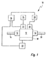
- An internal combustion engine carries in FIG. 1 in its entirety the reference numeral 10. It comprises a plurality of combustion chambers, of which only one is shown in FIG. 1 with the reference numeral 12. It is fed combustion air from a suction pipe 14 via an inlet valve 16. The combustion exhaust gases pass through an exhaust valve 18 into an exhaust pipe 20.
- Fuel is injected into the combustion chamber 12 directly via a fuel injector 22.
- This is an injector whose valve element (not shown) by a piezoelectric actuator (not shown) is moved.
- the injector 22 is connected to a fuel system 24. This provides the injector 22 with the fuel under very high pressure.
- the fuel-air mixture in the combustion chamber 12 is ignited by a spark plug 26, which is connected to an ignition system 28.
- the rotational speed of a crankshaft 30 and its angular position and angular accelerations are tapped by a sensor 32.
- the corresponding signals are fed to a control and regulating device 34.
- the control and regulating device 34 controls, inter alia, the injector 22.
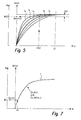
- FIG. 2 A stroke throttle curve of the injector 22 is shown in Fig. 2: From this it can be seen that the fuel mass flow Qstat rises steeply in a first region of the stroke h (Hubdroshnereich 36), whereas it is in the further course of the stroke h of the valve element of the injector 22 practically no longer increased (seat throttle area 38).
- the Hubdroshnereich 36 is particularly important because nowadays large amounts of fuel are introduced by a plurality of Kleinsteinspritzept. In these injector 22 opens only slightly. It thus essentially remains in the Hubdroshnereich 36.
- the characteristic curve not only establishes a relationship between the drive voltage U of the piezoactuator of the injector 22 with the fuel Mass flow Qstat but also between the drive voltage U and the torque M produced.
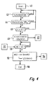
- the internal combustion engine 10 of FIG 4 (this method is stored as a computer program in the control unit 34):
- a query is made in block 42 as to whether internal combustion engine 10 is currently operating in stratified mode. This query is necessary because only in stratified operation a direct relationship between the torque M and the fuel mass flow Qstat is given. Only this direct relationship, as explained below, makes it possible to determine the quantities required for the compensation of said deviations.
- a block 44 it is queried whether a check of the characteristics of the injectors 22 is due. Such a check is not always necessary, but only at certain cyclic intervals. If the answer in block 44 is "yes", a query is made in block 46 as to whether the drive voltage U is greater than a limit value G1. This ensures that the internal combustion engine 10 is at an operating point in which the valve element of the injector 22 assigned to the piezoactuator is in a position in which the fuel mass flow Qstat is predominantly determined by seat throttling.
- the limit value G1 is also shown in FIG. 5, the seat throttling area is located to the right of the corresponding dashed line.
- the drive voltage U is now gradually reduced.
- the corresponding torque M also drops when the drive voltage U is reduced.
- this torque drop dM exceeds a limit value G2.
- This torque is designated MG2 in FIG. From this torque MG2 now the corresponding fuel mass flow QstatG2 is determined. From the drive voltage UG2, with which the injection was effected, which led to the torque MG2, and from the fuel mass flow QstatG2 now a pair of values is formed.
- QstatG2 would be such that the valve characteristic fe would be the closest, an entry would also be made in an error memory and a message would be output to the user. This may be, for example, that on the dashboard of a motor vehicle, in which the internal combustion engine 10 is installed, a warning lamp lights up.
- the valve characteristic fe means that the fuel injection device 22 has aged so much that a drive energy is required to deliver a certain mass flow of fuel which is above a threshold (this threshold is not shown in FIG. 5) ) Shown. The user and a person performing the maintenance of the engine are thus notified of the condition of the corresponding fuel injection device. At the same time, however, it remains ensured that the fuel mass flow can be controlled or regulated in the desired manner.
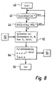
- FIG. 6 shows a second exemplary embodiment of a method with which the internal combustion engine of FIG. 1 can be operated.
- FIG. 6 shows a second exemplary embodiment of a method with which the internal combustion engine of FIG. 1 can be operated.
- those blocks which have equivalent functions to blocks of Fig. 4 bear the same reference numerals. They are not explained again in detail.
- the characteristic corresponding to the current state of the fuel injection device 22 is not selected from a previously established plurality of characteristics, but is specifically prepared for the fuel injection device 22 in question. This happens because when the internal combustion engine 10, the drive voltage U of the fuel injection device 22 is increased gradually. About the corresponding torque Mi, the associated fuel mass flows Qstati are determined.
- a value pair series Ui, Qstati is created.
- a function f (U, Qstat) is formed (block 60) which links a fuel mass flow Qstat, which is to be output by the fuel injection device 22, to a drive energy U to be supplied to the piezoactuator.
- the linking can be done by a linear interpolation. It will be understood that the method illustrated in FIGS. 6 and 7 does not operate during normal operation
- the internal combustion engine 10 may be performed, but must be performed, for example, during a maintenance stay.
- data pairs Ui drive voltage
- Qstati fuel mass flow
- each of the above-described methods is performed for each individual cylinder or fuel injector 22.
- the detection of the torque generated by the combustion of the fuel injected in the combustion chamber 12 is made by measuring the acceleration of the crankshaft 30 caused by this combustion.
- the acceleration of the crankshaft 30 is also determined from the signal of the sensor 32.
Landscapes
- Engineering & Computer Science (AREA)
- Chemical & Material Sciences (AREA)
- Combustion & Propulsion (AREA)
- Mechanical Engineering (AREA)
- General Engineering & Computer Science (AREA)
- Fuel-Injection Apparatus (AREA)
- Electrical Control Of Air Or Fuel Supplied To Internal-Combustion Engine (AREA)
- Combined Controls Of Internal Combustion Engines (AREA)
Abstract
Claims (13)
- Procédé de gestion d'un moteur à combustion interne (10) selon lequel le carburant est injecté directement dans au moins une chambre de combustion (12) par au moins un dispositif d'injection de carburant (22) dont l'élément de soupape est actionné par un actionneur piézoélectrique, et on détermine le couple de rotation (M) généré lors de la combustion de la quantité de carburant injectée dans la chambre de combustion (12) lors d'une injection,
caractérisé en ce qu'
à partir du couple de rotation (M) on détermine (52 ; 60 ; 64) au moins approximativement une courbe caractéristique de soupape (f) actuelle du dispositif d'injection de carburant (22) installé dans le moteur à combustion interne (10), la courbe caractéristique de soupape (f) combinant un débit massique de carburant (Qstat), qui doit être fourni par le dispositif d'injection de carburant (22), avec une énergie de commande (U) à fournir à l'actionneur piézoélectrique. - Procédé selon la revendication 1,
caractérisé en ce que
le procédé comprend les étapes suivantes :- à partir du couple de rotation (MG2), on détermine la quantité de carburant sur laquelle est basé, au moins théoriquement, ce couple de rotation (MG2), et à partir de cette quantité de carburant et de la durée d'ouverture associée du dispositif d'injection de carburant (22), on détermine le débit massique de carburant (QstatG2) correspondant;- à partir du débit massique de carburant (QstatG2) et de l'énergie de commande (UG2) de l'actionneur piézoélectrique avec laquelle l'injection a été déclenchée, laquelle avait généré le couple de rotation (MG2) on forme une paire de valeurs (UG2, QstatG2) ; et- à l'aide de cette paire de valeurs (UG2, QstatG2) composée de cette énergie de commande (UG2) et de ce débit massique de carburant (QstatG2), on choisit pour cet actionneur piézoélectrique celle des courbes caractéristiques de soupape (fc) parmi une multitude de courbes caractéristiques de soupape (fa, fb, fc, fd, fe) qui se situe au plus près de cette paire de valeurs (UG2, QstatG2). - Procédé selon la revendication 2,
caractérisé en ce qu'
on réduit (48) la tension de commande (U) de l'actionneur piézoélectrique à partir d'une valeur au-dessus d'une tension (G1) à laquelle l'élément de soupape associé à l'actionneur piézoélectrique est dans une position dans laquelle le débit massique de carburant (Qstat) est déterminé principalement par un étranglement de siège, et simultanément on surveille (50) le couple de rotation (M), basé sur les injections effectuées pendant la réduction de la tension de commande (U), et lorsque le couple de rotation (M) diminue au moins d'une valeur (G2) déterminée, on forme (52) la paire de valeurs (QstatG2, UG2) composée du débit massique de carburant (QstatG2) et de l'énergie de commande (UG2). - Procédé selon la revendication 1,
caractérisé en ce que
par une variation (58) de l'énergie de commande (U), on forme une série de paires de valeurs (Ui, Qstati) composées d'énergie de commande (Ui) et de débit massique de carburant (Qstati), et à partir de cette série de paires de valeurs (Ui, Qstati), on forme (60) une courbe caractéristique de soupape (f) qui combine un débit massique de carburant (Qstati), à fournir par le dispositif d'injection de carburant (22), avec une énergie de commande (U) à fournir à l'actionneur piézoélectrique. - Procédé selon la revendication 1,
caractérisé en ce qu'
à différents points de fonctionnement du moteur à combustion interne (10), on détermine (62) des paires de valeurs (Ui, Qstati) composées d'énergie de commande (Ui) et de débit massique de carburant (Qstati), et on adapte (64) à cette multitude de paires de valeurs (Ui, Qstati) une fonction standard (f), en particulier une fonction exponentielle, qui combine un débit massique de carburant (Qstat), à fournir par le dispositif d'injection de carburant (22), avec une énergie de commande (U) à fournir à l'actionneur piézoélectrique, pour ainsi former la courbe caractéristique de soupape (f). - Procédé selon la revendication 5,
caractérisé en ce que
l'adaptation (64) s'effectue suivant la méthode des plus petits carrés d'erreurs. - Procédé selon l'une quelconque des revendications 3 à 6,
caractérisé en ce que
l'énergie de commande (U) est variée (48, 58) respectivement pas à pas. - Procédé selon l'une quelconque des revendications précédentes,
caractérisé en ce que
le procédé est réalisé cycliquement dans des intervalles de temps prédéterminés. - Procédé selon l'une quelconque des revendications précédentes,
caractérisé en ce qu'
on fait un enregistrement dans une mémoire d'erreurs et/ou on émet un message si l'énergie de commande de l'actionneur piézoélectrique nécessaire pour fournir un débit massique de carburant déterminé atteint un seuil minimum. - Programme informatique,
caractérisé en ce qu'
il est exécuté pour la mise en oeuvre du procédé selon l'une quelconque des revendications précédentes lorsqu'il est réalisé sur un ordinateur. - Programme informatique selon la revendication 10,
caractérisé en ce qu'
il est stocké dans une mémoire, en particulier une mémoire flash ou un RAM de ferrite. - Appareil de commande et/ou de régulation (34) pour faire fonctionner un moteur à combustion interne (10),
caractérisé en ce qu'
il comprend une mémoire contenant un programme informatique selon l'une quelconque des revendications 10 ou 11. - Moteur à combustion interne (10) comprenant au moins une chambre de combustion (12), avec au moins un dispositif d'injection de carburant (22) muni d'un actionneur piézoélectrique et par lequel le carburant arrive directement dans la chambre de combustion (12), et avec un dispositif (32) permettant de déterminer le couple de rotation (M) généré lors de la combustion de la quantité de carburant injectée dans la chambre de combustion (12) lors d'une injection,
caractérisé en ce qu'
il comprend un appareil de commande et/ou de régulation (34) selon la revendication 12.
Applications Claiming Priority (3)
| Application Number | Priority Date | Filing Date | Title |
|---|---|---|---|
| DE10147814 | 2001-09-27 | ||
| DE2001147814 DE10147814A1 (de) | 2001-09-27 | 2001-09-27 | Verfahren, Computerprogramm und Steuer- und/oder Regelgerät zum Betreiben einer Brennkraftmaschine, sowie Brennkraftmaschine |
| PCT/DE2002/002995 WO2003031787A1 (fr) | 2001-09-27 | 2002-08-16 | Procede, programme informatique et appareil de commande et/ou de regulation permettant de faire fonctionner un moteur a combustion interne, et moteur a combustion interne y relatif |
Publications (2)
| Publication Number | Publication Date |
|---|---|
| EP1432901A1 EP1432901A1 (fr) | 2004-06-30 |
| EP1432901B1 true EP1432901B1 (fr) | 2006-11-22 |
Family
ID=7700587
Family Applications (1)
| Application Number | Title | Priority Date | Filing Date |
|---|---|---|---|
| EP02767102A Expired - Lifetime EP1432901B1 (fr) | 2001-09-27 | 2002-08-16 | Procede, programme informatique et appareil de commande et/ou de regulation permettant de faire fonctionner un moteur a combustion interne, et moteur a combustion interne y relatif |
Country Status (4)
| Country | Link |
|---|---|
| EP (1) | EP1432901B1 (fr) |
| JP (1) | JP4235552B2 (fr) |
| DE (2) | DE10147814A1 (fr) |
| WO (1) | WO2003031787A1 (fr) |
Families Citing this family (11)
| Publication number | Priority date | Publication date | Assignee | Title |
|---|---|---|---|---|
| DE10256240A1 (de) * | 2002-12-02 | 2004-06-09 | Robert Bosch Gmbh | Verfahren zur Steuerung eines Kraftstoffzumeßsystems einer Brennkraftmaschine |
| DE10323488B4 (de) * | 2003-05-23 | 2011-08-11 | Robert Bosch GmbH, 70469 | Verfahren und Vorrichtung zur betriebspunktabhängigen Steuerung von Injektoren eines Kraftstoffzumesssystems einer Brennkraftmaschine |
| EP1526267A3 (fr) | 2003-10-21 | 2010-07-28 | Continental Automotive GmbH | Méthode et dispositif pour compenser la dérive d'un injecteur dans un moteur à combustion interne à injection directe |
| DE10349579B4 (de) * | 2003-10-24 | 2013-01-03 | Robert Bosch Gmbh | Verfahren und Steuergerät zum Steuern eines Startvorganges einer Brennkraftmaschine |
| DE102004054372B3 (de) * | 2004-11-10 | 2006-06-14 | Siemens Ag | Verfahren und Vorrichtung zum Bestimmen eines Kraftstoffmassenstroms bei einer Brennkraftmaschine |
| DE102005004442B4 (de) * | 2005-01-31 | 2006-11-16 | Siemens Ag | Verfahren und Vorrichtung zum Steuern einer Brennkraftmaschine |
| DE102006027823B4 (de) * | 2006-06-16 | 2008-10-09 | Continental Automotive Gmbh | Verfahren und Vorrichtung zum Anpassen der Ventilcharakteristik eines Kraftstoff-Einspritzventils |
| DE102006050171A1 (de) | 2006-10-25 | 2008-04-30 | Robert Bosch Gmbh | Verfahren zur Bestimmung eines Kennfeldes der Einspritzmenge über einer elektrischen Größe eines elektrisch angesteuerten Einspritzventils |
| DE102008006674B4 (de) * | 2008-01-30 | 2020-08-27 | Bayerische Motoren Werke Aktiengesellschaft | Verfahren zum Betreiben einer Brennkraftmaschine mit Benzin-Direkteinspritzung |
| DE102010027806B4 (de) * | 2010-04-15 | 2024-01-18 | Robert Bosch Gmbh | Verfahren zum Betreiben einer Brennkraftmaschine, bei dem eine Größe ermittelt wird |
| DE102012209965A1 (de) * | 2012-06-14 | 2013-12-19 | Robert Bosch Gmbh | Verfahren zum Betreiben eines Ventils |
Family Cites Families (7)
| Publication number | Priority date | Publication date | Assignee | Title |
|---|---|---|---|---|
| JP2767959B2 (ja) * | 1990-02-27 | 1998-06-25 | 日産自動車株式会社 | ディーゼルエンジンの燃料噴射装置 |
| DE19652807C2 (de) * | 1996-12-18 | 2002-08-29 | Siemens Ag | Verfahren und Vorrichtung zum Ansteuern eines kapazitiven Stellgliedes |
| DE19652801C1 (de) * | 1996-12-18 | 1998-04-23 | Siemens Ag | Verfahren und Vorrichtung zum Ansteuern wenigstens eines kapazitiven Stellgliedes |
| JP3855473B2 (ja) * | 1998-07-08 | 2006-12-13 | いすゞ自動車株式会社 | コモンレール式燃料噴射装置 |
| DE19845037C2 (de) * | 1998-09-30 | 2000-11-30 | Siemens Ag | Verfahren und Anordnung zum Ansteuern eines kapazitiven Aktors |
| DE19931233B4 (de) * | 1999-07-07 | 2007-02-01 | Siemens Ag | Verfahren zum Ansteuern eines kapazitiven Stellgliedes |
| DE19936944A1 (de) * | 1999-08-05 | 2001-02-08 | Bosch Gmbh Robert | Verfahren zum Zumessen von Brennstoff mit einem Brennstoffeinspritzventil |
-
2001
- 2001-09-27 DE DE2001147814 patent/DE10147814A1/de not_active Ceased
-
2002
- 2002-08-16 DE DE50208805T patent/DE50208805D1/de not_active Expired - Lifetime
- 2002-08-16 JP JP2003534740A patent/JP4235552B2/ja not_active Expired - Fee Related
- 2002-08-16 EP EP02767102A patent/EP1432901B1/fr not_active Expired - Lifetime
- 2002-08-16 WO PCT/DE2002/002995 patent/WO2003031787A1/fr not_active Ceased
Also Published As
| Publication number | Publication date |
|---|---|
| WO2003031787A1 (fr) | 2003-04-17 |
| JP2005504912A (ja) | 2005-02-17 |
| DE10147814A1 (de) | 2003-05-08 |
| JP4235552B2 (ja) | 2009-03-11 |
| EP1432901A1 (fr) | 2004-06-30 |
| DE50208805D1 (de) | 2007-01-04 |
Similar Documents
| Publication | Publication Date | Title |
|---|---|---|
| DE602004003390T2 (de) | Verfahren zur echtzeitbestimmung einer kraftstoffeinspritzungsströmungscharakteristik | |
| DE102004006294B3 (de) | Verfahren zur Gleichstellung der Einspritzmengenunterschiede zwischen den Zylindern einer Brennkraftmaschine | |
| WO2007065573A1 (fr) | Procede de regulation d'un moteur a combustion interne, notamment d'un moteur a combustion interne a autoallumage | |
| DE102008040059A1 (de) | Kraftstoffeinspritzsteuergerät | |
| EP1432901B1 (fr) | Procede, programme informatique et appareil de commande et/ou de regulation permettant de faire fonctionner un moteur a combustion interne, et moteur a combustion interne y relatif | |
| DE10148217C1 (de) | Verfahren, Computerprogramm und Steuer- und/oder Regelgerät zum Betreiben einer Brennkraftmaschine, sowie Brennkraftmaschine | |
| EP2035676A1 (fr) | Procédé et dispositif d'adaptation des caractéristiques d'un injecteur de carburant | |
| DE10311141B4 (de) | Verfahren, Computerprogramm, Speichermedium und Steuer- und/oder Regelgerät zum Betreiben einer Brennkraftmaschine, sowie Brennkraftmaschine insbesondere für ein Kraftfahrzeug | |
| DE102004022999B3 (de) | Verfahren zur Ermittlung der Steuerkennlinie eines Regenerierventils eines Kraftstoffdampf-Rückhaltesystems | |
| DE102008001412B4 (de) | Verfahren und Vorrichtung zum Betreiben eines Einspritzventils | |
| DE102004048008A1 (de) | Verfahren zum Betreiben einer Brennkraftmaschine | |
| DE10302058B4 (de) | Verfahren zum Betreiben einer Brennkraftmaschine | |
| DE10303573B4 (de) | Verfahren, Computerprogramm, Speichermedium und Steuer- und/oder Regelgerät zum Betreiben einer Brennkraftmaschine, sowie Brennkraftmaschine insbesondere für ein Kraftfahrzeug | |
| WO2001063111A1 (fr) | Procede et dispositif pour commander un moteur a combustion interne multicylindre | |
| EP2633175A1 (fr) | Procédé pour surveiller une adaptation d'un temps d'injection d'une soupape d'injection d'un moteur à combustion interne | |
| EP1283952B1 (fr) | Procede de mise a niveau de cylindres d'un moteur a combustion interne | |
| DE102004040926B4 (de) | Verfahren zum Betreiben einer Brennkraftmaschine | |
| DE10149960C1 (de) | Verfahren, Computerprogramm, Steuer- und/oder Regelgerät zum Betreiben einer Brennkraftmaschine, sowie Brennkraftmaschine | |
| DE10026273C2 (de) | Verfahren zur Zylindergleichstellung bei einer Verbrennungskraftmaschine | |
| DE10359306A1 (de) | Verfahren und Vorrichtung zum Betreiben einer Brennkraftmaschine | |
| DE10038565C2 (de) | Kraftstoffversorgungssystem für eine Brennkraftmaschine insbesondere eines Kraftfahrzeugs | |
| EP1286036B1 (fr) | Procédé pour influencer l'émission de substances nocives et/ou l'émission de bruit d'un moteur à combustion interne et dispositif d'injection de combustible | |
| EP2520788A2 (fr) | Procédé de commander d'un système d'injection de carburant d'un moteur à combustion interne | |
| EP1296053B1 (fr) | Procédé d'injection directe de combustible sous forme de deux injections ayant des angles d'injection différents et dispositif de commande d'injection | |
| DE10235105B4 (de) | Verfahren zum Betreiben einer Brennkraftmaschine insbesondere eines Kraftfahrzeugs |
Legal Events
| Date | Code | Title | Description |
|---|---|---|---|
| PUAI | Public reference made under article 153(3) epc to a published international application that has entered the european phase |
Free format text: ORIGINAL CODE: 0009012 |
|
| 17P | Request for examination filed |
Effective date: 20040427 |
|
| AK | Designated contracting states |
Kind code of ref document: A1 Designated state(s): AT BE BG CH CY CZ DE DK EE ES FI FR GB GR IE IT LI LU MC NL PT SE SK TR |
|
| GRAP | Despatch of communication of intention to grant a patent |
Free format text: ORIGINAL CODE: EPIDOSNIGR1 |
|
| GRAS | Grant fee paid |
Free format text: ORIGINAL CODE: EPIDOSNIGR3 |
|
| GRAA | (expected) grant |
Free format text: ORIGINAL CODE: 0009210 |
|
| AK | Designated contracting states |
Kind code of ref document: B1 Designated state(s): DE FR IT |
|
| REF | Corresponds to: |
Ref document number: 50208805 Country of ref document: DE Date of ref document: 20070104 Kind code of ref document: P |
|
| ET | Fr: translation filed | ||
| PLBE | No opposition filed within time limit |
Free format text: ORIGINAL CODE: 0009261 |
|
| STAA | Information on the status of an ep patent application or granted ep patent |
Free format text: STATUS: NO OPPOSITION FILED WITHIN TIME LIMIT |
|
| 26N | No opposition filed |
Effective date: 20070823 |
|
| PGFP | Annual fee paid to national office [announced via postgrant information from national office to epo] |
Ref country code: FR Payment date: 20090819 Year of fee payment: 8 |
|
| PGFP | Annual fee paid to national office [announced via postgrant information from national office to epo] |
Ref country code: IT Payment date: 20090824 Year of fee payment: 8 |
|
| REG | Reference to a national code |
Ref country code: FR Ref legal event code: ST Effective date: 20110502 |
|
| PG25 | Lapsed in a contracting state [announced via postgrant information from national office to epo] |
Ref country code: IT Free format text: LAPSE BECAUSE OF NON-PAYMENT OF DUE FEES Effective date: 20100816 |
|
| PG25 | Lapsed in a contracting state [announced via postgrant information from national office to epo] |
Ref country code: FR Free format text: LAPSE BECAUSE OF NON-PAYMENT OF DUE FEES Effective date: 20100831 |
|
| PGFP | Annual fee paid to national office [announced via postgrant information from national office to epo] |
Ref country code: DE Payment date: 20141024 Year of fee payment: 13 |
|
| REG | Reference to a national code |
Ref country code: DE Ref legal event code: R119 Ref document number: 50208805 Country of ref document: DE |
|
| PG25 | Lapsed in a contracting state [announced via postgrant information from national office to epo] |
Ref country code: DE Free format text: LAPSE BECAUSE OF NON-PAYMENT OF DUE FEES Effective date: 20160301 |