EP1432935B1 - Bras de commande - Google Patents
Bras de commande Download PDFInfo
- Publication number
- EP1432935B1 EP1432935B1 EP02800581A EP02800581A EP1432935B1 EP 1432935 B1 EP1432935 B1 EP 1432935B1 EP 02800581 A EP02800581 A EP 02800581A EP 02800581 A EP02800581 A EP 02800581A EP 1432935 B1 EP1432935 B1 EP 1432935B1
- Authority
- EP
- European Patent Office
- Prior art keywords
- gearshift
- gearshift arm
- edge
- recess
- arm according
- Prior art date
- Legal status (The legal status is an assumption and is not a legal conclusion. Google has not performed a legal analysis and makes no representation as to the accuracy of the status listed.)
- Expired - Lifetime
Links
- 239000002184 metal Substances 0.000 claims description 32
- 239000000463 material Substances 0.000 claims description 11
- 238000000034 method Methods 0.000 claims description 8
- 229910000831 Steel Inorganic materials 0.000 claims description 7
- 239000010959 steel Substances 0.000 claims description 7
- 238000003466 welding Methods 0.000 claims description 7
- 238000007493 shaping process Methods 0.000 claims description 2
- 230000002035 prolonged effect Effects 0.000 claims 2
- 239000000956 alloy Substances 0.000 claims 1
- 229910045601 alloy Inorganic materials 0.000 claims 1
- 238000005520 cutting process Methods 0.000 description 21
- 238000004519 manufacturing process Methods 0.000 description 8
- 238000003754 machining Methods 0.000 description 7
- 230000015572 biosynthetic process Effects 0.000 description 5
- 238000004049 embossing Methods 0.000 description 4
- 238000004080 punching Methods 0.000 description 4
- 239000011324 bead Substances 0.000 description 3
- 230000005540 biological transmission Effects 0.000 description 3
- 239000007858 starting material Substances 0.000 description 3
- 230000000903 blocking effect Effects 0.000 description 2
- 240000006240 Linum usitatissimum Species 0.000 description 1
- 238000004873 anchoring Methods 0.000 description 1
- 238000005452 bending Methods 0.000 description 1
- 238000010276 construction Methods 0.000 description 1
- 238000009499 grossing Methods 0.000 description 1
- 230000006698 induction Effects 0.000 description 1
- 238000009434 installation Methods 0.000 description 1
- 230000002093 peripheral effect Effects 0.000 description 1
- 238000005096 rolling process Methods 0.000 description 1
Images

Classifications
-
- F—MECHANICAL ENGINEERING; LIGHTING; HEATING; WEAPONS; BLASTING
- F16—ENGINEERING ELEMENTS AND UNITS; GENERAL MEASURES FOR PRODUCING AND MAINTAINING EFFECTIVE FUNCTIONING OF MACHINES OR INSTALLATIONS; THERMAL INSULATION IN GENERAL
- F16H—GEARING
- F16H63/00—Control outputs from the control unit to change-speed- or reversing-gearings for conveying rotary motion or to other devices than the final output mechanism
- F16H63/02—Final output mechanisms therefor; Actuating means for the final output mechanisms
- F16H63/30—Constructional features of the final output mechanisms
- F16H63/32—Gear shift yokes, e.g. shift forks
-
- F—MECHANICAL ENGINEERING; LIGHTING; HEATING; WEAPONS; BLASTING
- F16—ENGINEERING ELEMENTS AND UNITS; GENERAL MEASURES FOR PRODUCING AND MAINTAINING EFFECTIVE FUNCTIONING OF MACHINES OR INSTALLATIONS; THERMAL INSULATION IN GENERAL
- F16H—GEARING
- F16H63/00—Control outputs from the control unit to change-speed- or reversing-gearings for conveying rotary motion or to other devices than the final output mechanism
- F16H63/02—Final output mechanisms therefor; Actuating means for the final output mechanisms
- F16H63/30—Constructional features of the final output mechanisms
- F16H63/32—Gear shift yokes, e.g. shift forks
- F16H2063/322—Gear shift yokes, e.g. shift forks characterised by catches or notches for moving the fork
-
- F—MECHANICAL ENGINEERING; LIGHTING; HEATING; WEAPONS; BLASTING
- F16—ENGINEERING ELEMENTS AND UNITS; GENERAL MEASURES FOR PRODUCING AND MAINTAINING EFFECTIVE FUNCTIONING OF MACHINES OR INSTALLATIONS; THERMAL INSULATION IN GENERAL
- F16H—GEARING
- F16H63/00—Control outputs from the control unit to change-speed- or reversing-gearings for conveying rotary motion or to other devices than the final output mechanism
- F16H63/02—Final output mechanisms therefor; Actuating means for the final output mechanisms
- F16H63/30—Constructional features of the final output mechanisms
- F16H63/32—Gear shift yokes, e.g. shift forks
- F16H2063/327—Gear shift yokes, e.g. shift forks essentially made of sheet metal
-
- Y—GENERAL TAGGING OF NEW TECHNOLOGICAL DEVELOPMENTS; GENERAL TAGGING OF CROSS-SECTIONAL TECHNOLOGIES SPANNING OVER SEVERAL SECTIONS OF THE IPC; TECHNICAL SUBJECTS COVERED BY FORMER USPC CROSS-REFERENCE ART COLLECTIONS [XRACs] AND DIGESTS
- Y10—TECHNICAL SUBJECTS COVERED BY FORMER USPC
- Y10T—TECHNICAL SUBJECTS COVERED BY FORMER US CLASSIFICATION
- Y10T74/00—Machine element or mechanism
- Y10T74/20—Control lever and linkage systems
-
- Y—GENERAL TAGGING OF NEW TECHNOLOGICAL DEVELOPMENTS; GENERAL TAGGING OF CROSS-SECTIONAL TECHNOLOGIES SPANNING OVER SEVERAL SECTIONS OF THE IPC; TECHNICAL SUBJECTS COVERED BY FORMER USPC CROSS-REFERENCE ART COLLECTIONS [XRACs] AND DIGESTS
- Y10—TECHNICAL SUBJECTS COVERED BY FORMER USPC
- Y10T—TECHNICAL SUBJECTS COVERED BY FORMER US CLASSIFICATION
- Y10T74/00—Machine element or mechanism
- Y10T74/20—Control lever and linkage systems
- Y10T74/20576—Elements
- Y10T74/20582—Levers
Definitions
- the invention relates to a switching arm made of sheet metal for the transmission of switching movements.
- Such switching arms are fixedly arranged on switching elements such as shift shafts or shift forks.
- the shift shafts are slidably and / or pivotally mounted in the transmission.
- the shift forks sit z.
- the switching elements are moved and / or pivoted by means of a shift finger or a similarly designed actuating element.
- the actuating element engages in a switching jaw or a similarly formed recess on the switching arm and transmits switching movements to the switching element.
- Locking cylinders or the like which prevent a misoperation of gears, also often engage in the shifting mouth.
- the switching arms are usually stamped parts.
- the contact surfaces for the shift finger are in the switching mouth of a switching arm usually opposite each other. Their distance and their alignment must be carried out with a very high accuracy. Likewise, the requirements for the dimensional accuracy of other other functional surfaces in the switching mouth, such. B. functional surfaces for the engagement of a locking cylinder, very high.
- the required accuracies for the functional dimensions, such as the distance of the opposing contact surfaces in the shift mouth, and functional surfaces, as for the switching jaw limiting and required for the gentle tracking of the shift finger in the shift jaw chamfers and rounded edges on body edges are in the rules only to achieve by machining rework. Functional surfaces are partly due to the punching tear after punching at the cutting edge of the parts for a frictional contact with the shift finger too rough and must therefore be machined by machining.
- the material used for producing the switching arms is relatively high.
- the switching arms are relatively heavy due to their massive construction and their shape design is limited due to the material thickness of the starting material.
- the production of the switching arms is very costly for the above reasons, especially in mass production and mass production.
- a switching arm of the generic type shows FR 27 62 659.
- a switch arm made of thick sheet metal is attached to a shift fork. This switching arm has a switching mouth.
- the wall of the switching arm is reinforced in the field of Wegmaules to create contact surfaces of sufficient width.
- DE 199 19 271 A1 discloses a switching rocker made of sheet metal, which is pre-punched from a blank made of sheet steel before it is formed by a bending operation to the finished component.
- the object of the invention is therefore to provide a switching arm which does not have the aforementioned disadvantages.
- the switching arm is a formed from thin sheet metal forming part.
- the advantages of a switching arm according to the invention in comparison with the prior art are the low costs for its production, especially in mass production and mass production.
- the consumption of material for the production of such a switching arm is low.
- the weight of this switching arm is reduced by up to 50% compared to the switching arms initially described.
- the thin material allows almost unlimited designs.
- the required accuracies for functional dimensions such as the distance of the opposing contact surfaces in the shift jaw, and functional surfaces, as for the location and dimensioning of chamfers and curves for the gentle engagement of the shift finger in the shift jaw, is usually only by the or Form processes achievable. Machining is usually unnecessary.
- the switching arms are preferably used.
- the materials used are sheets made from St35, Ck45, C35 and low-alloyed deep-drawing steels such as 16MnCr5, all weldable and other malleable steels and deep-drawing steels.
- the switching arms are preferably fixed by welding to switching elements, such as shift rails and shift forks.
- a hard surface has in particular the contact surfaces.
- the switching arms according to the invention are surface hardened in the area of the muzzle by induction hardening process. It is also conceivable for reasons of cost to harden the entire switching arm or the switching arm welded to the switching element as a unit. Depending on the type of steel used, case hardening or hardening methods can be used.
- the switching arm is a formed from thin sheet metal formed forming part with a mouth open to an edge of the switching arm recess for the engagement of a shift finger.
- the switching jaw for the engagement of the shift finger is created on the switching arm.
- the switching mouth is z. B. created by a step of excising in a multi-stage forming process or by punching with subsequent embossing or passing through the edges of the muzzle.
- contact surfaces for the shift finger By passing through the edges of the recess or by their embossing are created in a further embodiment of the invention contact surfaces for the shift finger.
- the sheet metal at the edges of the recess is preferably placed through so that the sheet is angled from the actual flat body of the switching arm, usually at right angles but also at any other angle, and possibly forms an edge bordering the entire recess.
- the width of the edge is determined by the required width of the contact surfaces embossed on the edge or produced by means of calibrating and / or depending on the rigidity requirements of the switching arm.
- the contact surfaces for the shift finger lie in the shift mouth usually opposite each other. Their distance and their alignment must be carried out with a very high accuracy. Likewise, the requirements for the dimensional accuracy of other functional surfaces in the switching mouth, such. B. of functional surfaces for the installation of a locking cylinder, very high. These accuracies for the functional dimensions, such as the distance of the opposing contact surfaces in the shift jaw and their orientation to each other, are generally allowable without machining rework.
- the recess is delimited at least by two plane-parallel opposed and mutually facing non-cutting contact surfaces on angled portions of the sheet, wherein the distance between the opposing contact surfaces by non-cutting machining with a Accuracy is performed, which allows a deviation from the target value of the distance of a maximum of 1/10 mm.
- Functional surfaces such as the contact surfaces and as the switching mouth or the contact surfaces delimiting and required for the smooth meshing of the shift finger in the shift mouth chamfers and curves on body edges are introduced without cutting.
- the surface of these functional surfaces is smooth and solidified due to embossing or calibration. The wear resistance of the surfaces is increased. Machining smoothing is eliminated.
- a further embodiment of the invention provides that the recess is bounded at least by two oppositely facing and mutually facing non-cutting shaped contact surfaces on angled portions of the sheet.
- the switching arm has at least one body edge bordering the contact surface, at least on one side to a further lateral surface of the switching arm, with a chamfer formed without a chip.
- a distance describing the bevel in the cross-section of the switching arm between an edge bordering the chamfer surface and an imaginary cutting edge has an accuracy which permits a deviation from the maximum value of the distance of 1/10 mm.
- the imaginary cutting edge is a common cutting edge parallel to the edge of the starting surface extended beyond the chamfer with the further lateral surface of the switching arm extended beyond the chamfer. The distance of the edge separating the abutment surface from the surface created by the chamfer is thus very precisely and more precisely than the distance by machining possible to the vertex of an imaginary unbroken body edge.
- the switching arm is a flat formed of thin sheet metal forming shaped part, wherein the forming part is fork-shaped at one end and is provided at the end with two prong-shaped projections.
- the switching arm also has at least one edge formed by an angled sheet on its outer contour.
- Each of the projections is provided at one of the plate of the switching arm angled portion at least with a stop surface, the one another, opposite to the other of the projections opposite stop surface, opposite.
- the switching arm has at least one tab bent from the switching arm and that the switching arm is connected to a switching element by means of at least one weld on the tab.
- the tab is attached to the switching element by suitable welding methods, such as laser welding, resistance welding or gas shielded arc welding.
- the switching arm is provided with at least one bead-like shape.
- the switching arm Against buckling of the switching arm and to increase the torsional rigidity of the switching arm on the various wall sections is appropriately provided with one or more beads, non-cutting produced duplications, embossing, the sheet or bends of the sheet metal at the edges.
- a possibly circumferentially reinforced edge on the substantially flat trained switching arm is produced by a bead or by angled at the edge of the flat body sheet.
- the invention provides, in particular for higher loads, before that the switching arm is a console-shaped from thin sheet metal formed without forming part.
- the switching arm in this case has a first wall portion with a mouth-shaped open to an edge of the switching arm recess for the engagement of a shift finger.
- the recess is bounded at least by two mutually opposite and facing each other chipless shaped contact surfaces on angled portions of the sheet.
- the first wall section merges in one piece into three further wall sections angled away from the first wall section and pointing in the same direction.
- An embodiment of the invention further provides that the other three Wall sections of the switching arm are also integrally formed with each other.
- the switching arm is thus formed by a cup-shaped drawn part.
- it is provided that the wall sections of the switching arm suspended from one another in a flat circuit board are folded out of the flat blank, brought together and welded at the contact points, so that the sheet metal part receives a cup-shaped or console-like shape.
- the switching arm has at least one of the wall sections at least one bead-like shape. Against buckling of the switching arm and to increase the torsional stiffness of the switching arm is provided at least one or each or all of the different wall sections appropriately with one or more beads, non-cutting generated doublings, embossments, throats of the sheet or folds of the sheet at the edges.
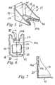
- a switching arm 1 is shown.
- the switching arm 1 is a flat made of 2mm thin sheet metal forming shaped part.
- the forming part is fork-shaped, formed and has two prong-shaped projections 2 and 3.
- the projections 2 and 3 define a recess 4.
- the recess 4 is partially bounded by four opposing thrust surfaces 2a, 2b, 3a, 3b.
- an unillustrated shift finger starts.
- the mutually oppositely formed stop surfaces 2b and 3b are in a blocking position a stop for a locking cylinder or locking pin, not shown.
- Each of the contact surfaces 2 a, 2 b, 3 a, 3 b is formed on a section lapping the recess 4 and being angled away from the sheet metal of the switching arm 1 or the projections 2 and 3.
- the contact surfaces 2a and 3a face each other and are aligned plane-parallel to each other.
- the clear distance D between the contact surfaces 2a and 3a is performed by non-cutting forming with an accuracy that allows a deviation from the target value of the distance of a maximum of 1/10 mm.
- the body edge 5 is rounded at the level of the contact surfaces 2a and 3a by forming. The rounding has a radius which is smaller than the wall thickness of the switching arm 1 in the region of the stop surfaces 2a and 3a.
- the rear lateral surface 6 and thus the body edge 5, opposite flat side of the switching arm 1 with the front lateral surface 7, the contact surfaces 2a and 3a are delimited by a further body edge 8.
- This body edge 8 has a chamfer 8a at least at the level of the contact surface 2a and a chamfer 8b at the level of the contact surface 3a.
- the chamfer 8a in cross-section (FIG. 4) together with the angle ⁇ 1 describing distance d 1 from the edge 8c to an aligned parallel to the edge 8c imaginary common cutting edge 9 is executed with an accuracy that a deviation of the setpoint of maximum 1/10 mm allows.
- the edge 8c delimits the contact surface 2a to the chamfer 8a.
- the cutting edge 9 is a cutting edge, which would form an imaginary and non-chamfered body edge between the contact surface 2a and the front lateral surface 7.
- cutting edge 9a is, as the distance d 1, with a Accuracy executed, which allows a deviation of the setpoint of a maximum of 1/10 mm.
- the edge 8d is an edge bordering the contact surface 3a to the chamfer 8b.
- the cutting edge 9a is a parallel to the edge 8d aligned cutting edge, which would form an imaginary and non-chamfered body edge between the abutment surface 3a and the front lateral surface 7.
- the switching arm 1 is reinforced on its outline with a formed from angled sheet metal of the switching arm 1 edge 1a against improper deformation under load. Furthermore, the switching arm 1 has a bead-like shape 10, which also leads to a high rigidity of the sheet metal part.
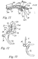
- FIG. 13 shows, for example, how the switching arm 1 is fastened to the guide eye 12a of a shift fork 12 by means of the lug 11.
- the tab 11 is bent to the shape of the guide eye 12 a rounded rounded and is welded to the guide eye 12 a fitting with the guide eye 12 a.
- a switching arm 13 is a forming part of thin sheet metal with a console-like shape.
- the switching arm 13 is formed from a first wall section 14 and three further wall sections 15, 16 and 17.
- the three wall sections 15, 16 and 17 go, formed integrally with the first wall section 14, pointing at right angles and pointing in the same direction from the first wall section 14 and are also connected to one another at the corners 18 and 19 in one piece.
- the wall portion 15 functions as a support plate of the switching arm 13, on which the first wall portion 14 under load, by z. B. shift finger, not shown, on the functioning as a node plates wall sections 16 and 17 is supported.
- the first wall section 14 has a sickle-shaped formation 20, which leads like the wall sections 16 and 17 to a high rigidity of the sheet metal part.
- the first wall section 14 is provided with a mouth-shaped recess 14a which is open to the free edge of the wall section 14.
- the recess 14a is lined at its peripheral edge 14b with angled from the flat wall portion 14 plate.
- each non-cutting contact surfaces 14c and 14d are formed in the sheet metal of the edge 14a.
- the contact surfaces 14c and 14d are located opposite each other at the recess 14a and are aligned parallel to each other.
- the distance D between the abutment surfaces 14c and 14d is carried out by cold forming of sheet metal with an accuracy that allows a deviation of the distance D from its nominal value of a maximum of 1/10 mm.
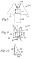
- FIGs 9 and 10 show an alternative embodiment of a switching arm 21 to the switching arm of Figure 5.
- the switching arm 21 is formed of a first wall portion 22 and three further wall portions 23, 24 and 25.
- Figure 8 shows the unfinished switching arm 21 in the form of a partially formed on the switching mouth blank 28.
- the flat on this blank 28 in the plane of the wall portion 22 present wall portions 23, 24 and 25 are integrally connected to the wall portion 22.
- the wall sections 23, 24 and 25 are bent at right angles and the same direction points away from the first wall section 22.
- the wall sections 23 and 24 or 23 and 25 are brought together and welded together.
- FIGS 11 and 12 show a switching arm 29.
- the switching arm 29 is a substantially flat formed forming part of thin sheet metal.
- the switching arm 29 is angled in its main plane running in two legs 30 and 31 running.
- the leg 30 is fork-shaped at its free end and has two prong-shaped projections 32 and 33.
- the projections 32 and 33 define a recess 34.
- the recess 34 is partially formed by four opposing abutment surfaces 32a, 32b, 33a, 33b limited for a shift finger, not shown.
- the opposing abutment surfaces 32b and 33b are in a blocking position a stop for a locking cylinder or locking pin, not shown.
- Each of the abutment surfaces 32a, 32b, 33a, 33b is formed on a portion 29a which lends the recess 34 and is angled away from the sheet metal of the switching arm 29.
- the abutment surfaces 32a and 33a face each other and their surface is slightly bulged from the body edges 35 and 36 to the center of the respective abutment surface 32a and 33a outwardly into the recess 34.
- the switching arm 29 is reinforced on its outline with an edge 29b formed from bent sheet metal of the switching arm 29 against impermissible deformation under load. Furthermore, the switching arm 29 has a bead-like shape 31a on the leg 31 and a bead-like shape 30a on the leg 30, which also lead to a high rigidity of the sheet metal part. From the switching arm 29 is a tab 31b, which is provided for the attachment of the switching arm 29 at a movable to its longitudinal central axis switching element.
- FIG. 12 shows how the switching arm 29 is fastened to a switching rod 37, for example by means of the tab 31b.
- the tab 31b is the shape of the cylindrical outer shell of the shift rod 37 adapted curved rounded and welded to the shift rod 37 fitting with the shift rod 37.
- a shift fork 40 is attached on the shift rod 37.
- the shift rod 37 is displaceable by means of bearings 38 and 39 along its longitudinal central axis and pivotally mounted about its longitudinal central axis in a transmission, not shown.
Landscapes
- Engineering & Computer Science (AREA)
- General Engineering & Computer Science (AREA)
- Mechanical Engineering (AREA)
- Bending Of Plates, Rods, And Pipes (AREA)
- Gear-Shifting Mechanisms (AREA)
- Mechanical Control Devices (AREA)
- Agricultural Machines (AREA)
- Shaping Metal By Deep-Drawing, Or The Like (AREA)
Claims (20)
- Bras (1, 13, 21, 29) de changement de vitesse fait en tôle pour la transmission de mouvements de changement de vitesse, ledit bras (1, 13, 21, 29) de changement de vitesse étant une pièce formée sans enlèvement de copeaux à partir d'une tôle métallique à paroi mince ayant un évidement (4, 14a, 34) qui est ouvert en forme de bouche vers un bord du bras (1, 13, 21, 29) de changement de vitesse pour l'engagement d'un doigt de changement de vitesse, caractérisé en ce que la tôle métallique au bord de l'évidement (4, 14a, 34) est repliée.
- Bras de changement de vitesse selon la revendication 1, caractérisé en ce que, à son état de départ avant le formage du bras (1, 13, 21, 29) de changement de vitesse, la tôle métallique a une épaisseur de jusqu'à 2 mm.
- Bras de changement de vitesse selon la revendication 1, caractérisé en ce que la matière de base du bras (1, 13, 21, 29) de changement de vitesse est un acier d'emboutissage.
- Bras de changement de vitesse selon la revendication 1, caractérisé en ce que la matière de base du bras (1, 13, 21, 29) de changement de vitesse est un acier d'emboutissage faiblement allié.
- Bras de changement de vitesse selon la revendication 1, caractérisé en ce que le bras (1, 13, 21, 29) de changement de vitesse est relié par des procédés appropriés de soudage à un élément de changement de vitesse qui est déplaçable le long de son axe longitudinal central.
- Tringle (37) de changement de vitesse qui est déplaçable le long de son axe longitudinal central et qui peut pivoter autour de son axe longitudinal central, avec un bras de changement de vitesse selon la revendication 1.
- Fourchette (12) de changement de vitesse avec un bras de changement de vitesse selon la revendication 1.
- Bras de changement de vitesse selon la revendication 1, caractérisé en ce que l'évidement (4, 14a, 34) est défini, au moins partiellement, par, au moins, deux surfaces de butée opposées (2a, 2b, 3a, 3b, 14c, 14d, 32a, 32b, 33a, 33b) qui sont orientées l'une vers l'autre.
- Bras de changement de vitesse selon la revendication 1, caractérisé en ce que l'évidement (4, 14a) est défini, au moins partiellement, par, au moins, deux surfaces de butée (2a, 2b, 14c, 14d) opposées à faces parallèles qui sont orientées, l'une vers l'autre, en étant formées sans enlèvement de copeaux sur, au moins, une section (1b, 13a) repliée de la tôle métallique.
- Bras de changement de vitesse selon la revendication 1, caractérisé en ce que l'évidement (4, 14a) est défini, au moins partiellement, par, au moins, deux surfaces de butée (2a, 2b, 14c, 14d) opposées à faces parallèles qui sont orientées, l'une vers l'autre, en étant formées sans enlèvement de copeaux sur des sections (1b, 13a) repliées de la tôle métallique, la distance entre les surfaces de butée (2a, 2b, 14c, 14d) opposées étant réalisé sans enlèvement de copeaux avec une précision qui permet un écart maximal de 1/10 mm par rapport à la valeur voulue de cette distance.
- Bras de changement de vitesse selon la revendication 1, caractérisé en ce que l'évidement (4) est défini, au moins partiellement, par, au moins, deux surfaces de butée (2a, 3a) opposées qui sont orientées, l'une vers l'autre, en étant formées sans enlèvement de copeaux, un bord arrondi (5) de corps sans enlèvement de copeaux se raccordant à la surface de butée (2a, 3a), au moins d'un côté.
- Bras de changement de vitesse selon la revendication 1, caractérisé en ce que l'évidement (4) est défini, au moins partiellement, par, au moins, deux surfaces de butée (2a, 3a) opposées qui sont orientées, l'une vers l'autre, en étant formées sans enlèvement de copeaux sur au moins une section (1b) repliée de la tôle métallique, ledit bras (1) de changement de vitesse comprenant au moins un bord (8) de corps ayant un chanfrein (8a, 8b) formé sur celui-ci sans enlèvement de copeaux, et ledit bord (8) de corps délimitant, au moins d'un côté, la surface de butée (2a, 3a) par rapport à une surface extérieure (7) du bras (1) de changement de vitesse.
- Bras de changement de vitesse selon la revendication 1, caractérisé en ce que l'évidement (4) est défini, au moins partiellement, par, au moins, deux surfaces de butée (2a, 3a) opposées qui sont orientées, l'une vers l'autre, en étant formées sans enlèvement de copeaux sur au moins une section (1b) repliée de la tôle métallique, ledit bras (1) de changement de vitesse comprenant au moins un bord (8) de corps ayant un chanfrein (8a, 8b) formé sur celui-ci sans enlèvement de copeaux, et ledit bord (8) de corps délimitant, au moins d'un côté, la surface de butée (2a, 3a) par rapport à une surface extérieure (7) du bras (1) de changement de vitesse, et en ce que, une distance décrivant le chanfrein (8a, 8b) en coupe droite du bras (1) de changement de vitesse entre un bord (8c, 8d) qui délimite la surface de butée (2a, 3a) vers le chanfrein (8a, 8b) et, parallèle au bord (8c, 8b), un bord (9, 9a) de coupe commun, imaginaire de la surface de butée (2a, 3a) prolongée au delà du chanfrein (8a, 8b) avec la surface extérieure (7) du bras (1) de changement de vitesse prolongée au-delà du chanfrein (8a, 8b) possède une précision qui permet un écart maximal de 1/10 mm par rapport à la valeur voulue de cette distance.
- Bras de changement de vitesse selon la revendication 1, caractérisé en ce que la pièce formée a, à l'une des ses extrémités, une configuration bifurquée et comprend sur cette extrémité deux saillies (2, 3, 32, 33) en forme de bras de fourche et, au moins, un bord (1a, 29b) formé par de la tôle repliée, chacune des saillies (2, 3, 32, 33) possédant sur une section repliée (1b, 29a) au moins une surface de butée (2a, 2b, 3a, 3b, 32a, 32b, 33a, 33b) opposée à une autre surface de butée (2a, 2b, 3a, 3b, 32a, 32b, 33a, 33b) sur l'autre des saillies (2, 3, 32, 33).
- Bras de changement de vitesse selon la revendication 14, caractérisé en ce que le bras (1, 29) de changement de vitesse comprend au moins un talon (11, 31b) qui s'étend à partir du bras (1, 29) de changement de vitesse, et en ce que le bras (1, 29) de changement de vitesse est relié à un élément de changement de vitesse par au moins une soudure sur le talon (11, 31b).
- Bras de changement de vitesse selon la revendication 14, caractérisé en ce que le bras (1, 29) de changement de vitesse comprend au moins une partie formée (10, 31a, 30a) en forme de moulure dans la tôle métallique.
- Bras de changement de vitesse selon la revendication 1, caractérisé en ce que le bras (13, 21) de changement de vitesse est une pièce formée en forme de console, ledit bras (13, 21) de changement de vitesse comprenant une première section (14, 22) de paroi ayant un évidement (14a) qui est ouvert en forme de bouche vers un bord du bras (13, 21) de changement de vitesse pour l'engagement d'un doigt de changement de vitesse, ledit évidement (14a) étant défini, au moins partiellement, par, au moins, deux surfaces de butée (14c, 14d) opposées qui sont orientées, l'une vers l'autre, en étant formées sans enlèvement de copeaux sur des sections (13a) repliées de la tôle métallique, et ladite première section (14) de paroi se raccordant, d'un seul tenant, à trois autres sections (15, 16, 17) de paroi qui sont repliées à partir de la première section (14) de paroi en étant orientées dans la même direction.
- Bras de changement de vitesse selon la revendication 17, caractérisé en ce que les trois autres sections (15, 16, 17) de paroi sont configurées d'un seul tenant, l'une avec l'autre.
- Bras de changement de vitesse selon la revendication 17, caractérisé en ce que les trois autres sections (23, 24, 25) de paroi sont pliées à partir de la première section (22) de paroi, sont réunies, l'une à l'autre, et deux des autres sections (23, 24, 25) de paroi sont fixées, à chaque fois, l'une à l'autre.
- Bras de changement de vitesse selon la revendication 17, caractérisé en ce que le bras (13, 21) de changement de vitesse est muni au moins d'une partie formée (20) en forme de moulure dans la tôle métallique.
Applications Claiming Priority (3)
| Application Number | Priority Date | Filing Date | Title |
|---|---|---|---|
| DE10148980A DE10148980A1 (de) | 2001-10-04 | 2001-10-04 | Schaltarm |
| DE10148980 | 2001-10-04 | ||
| PCT/EP2002/010915 WO2003031848A1 (fr) | 2001-10-04 | 2002-09-28 | Bras de commande |
Publications (2)
| Publication Number | Publication Date |
|---|---|
| EP1432935A1 EP1432935A1 (fr) | 2004-06-30 |
| EP1432935B1 true EP1432935B1 (fr) | 2007-06-06 |
Family
ID=7701381
Family Applications (1)
| Application Number | Title | Priority Date | Filing Date |
|---|---|---|---|
| EP02800581A Expired - Lifetime EP1432935B1 (fr) | 2001-10-04 | 2002-09-28 | Bras de commande |
Country Status (5)
| Country | Link |
|---|---|
| US (3) | US20040187623A1 (fr) |
| EP (1) | EP1432935B1 (fr) |
| BR (1) | BR0206095A (fr) |
| DE (2) | DE10148980A1 (fr) |
| WO (1) | WO2003031848A1 (fr) |
Families Citing this family (7)
| Publication number | Priority date | Publication date | Assignee | Title |
|---|---|---|---|---|
| DE10202651B4 (de) * | 2002-01-23 | 2014-01-23 | Koki Technik Transmission Systems Gmbh | Getriebe |
| DE10326870B3 (de) * | 2003-06-14 | 2005-02-03 | Dieter Kirschdorf | Verfahren zur Herstellung eines Getriebeschaltelements aus Metall |
| GB2476072B (en) * | 2009-12-10 | 2017-02-01 | Gm Global Tech Operations Llc | Gearbox |
| CN206102165U (zh) * | 2016-07-13 | 2017-04-19 | 革新(厦门)运动器材有限公司 | 一种折叠床 |
| US10835048B2 (en) | 2016-08-31 | 2020-11-17 | Inno-Sports Co., Ltd. | Connection member and folding bed having same |
| US10738887B2 (en) * | 2018-02-06 | 2020-08-11 | Arvinmeritor Technology, Llc | Shift fork and method of manufacture |
| CN115157253A (zh) * | 2022-07-13 | 2022-10-11 | 陕西法士特齿轮有限责任公司 | 变速器外换挡臂装配方法、系统、装置、设备及存储介质 |
Family Cites Families (23)
| Publication number | Priority date | Publication date | Assignee | Title |
|---|---|---|---|---|
| DE1122385B (de) * | 1960-06-28 | 1962-01-18 | Opel Adam Ag | Aus Blech hergestellte Schaltgabel fuer Geschwindigkeitswechselgetriebe, insbesondere von Kraftfahrzeugen |
| DE1848789U (de) * | 1961-06-29 | 1962-03-22 | Bosch Gmbh Robert | Gabelfoermiger schwenkhebel, insbesondere zum einruecken des ritzelgetriebes von andrehmotoren fuer brennkraftmaschinen. |
| DE2528905C3 (de) * | 1975-06-28 | 1979-08-02 | Audi Nsu Auto Union Ag, 7107 Neckarsulm | Verfahren zur Herstellung von metallischen Ringen |
| US4259877A (en) * | 1979-07-16 | 1981-04-07 | Dana Corporation | Transmission shift control |
| US4793202A (en) * | 1984-10-09 | 1988-12-27 | Honda Giken Kogyo Kabushiki Kaisha | Vehicular transmission shift mechanism |
| US5189402A (en) * | 1987-05-14 | 1993-02-23 | Advanced Interaction, Inc. | Content addressable video system for image display |
| US5487318A (en) * | 1994-12-01 | 1996-01-30 | New Holland North America, Inc. | Shift fork actuated position sensor |
| GB9607194D0 (en) * | 1996-04-04 | 1996-06-12 | Eaton Corp | Improved single shaft shifting mechanism |
| FR2762659B1 (fr) * | 1997-04-25 | 1999-06-25 | Peugeot | Fourchette coulissante de boite de vitesses et agencement de cette fourchette sur un axe solidaire d'une fourchette en tole |
| GB2326203B (en) * | 1997-05-15 | 2001-12-19 | Sagar Richards Ltd | Improvements in or relating to selector forks |
| US5958603A (en) * | 1997-06-09 | 1999-09-28 | Atd Corporation | Shaped multilayer metal foil shield structures and method of making |
| US6038938A (en) * | 1997-10-14 | 2000-03-21 | New Venture Gear, Inc. | Shift fork/gate assembly |
| US6189402B1 (en) * | 1997-12-09 | 2001-02-20 | Isuzu Motors Limited | Gear transmission |
| DE19757184A1 (de) * | 1997-12-22 | 1999-06-24 | Schaeffler Waelzlager Ohg | Schaltgabel für ein Gangschaltgetriebe eines Kraftfahrzeugs |
| FR2778444B1 (fr) * | 1998-05-05 | 2000-06-23 | Renault | Boite de vitesses compacte |
| FR2782768B1 (fr) * | 1998-09-02 | 2000-11-03 | Coutier Moulage Gen Ind | Procede de fabrication d'une fourchette de boite de vitesses et fourchette ainsi obtenue |
| DE19845146A1 (de) * | 1998-10-01 | 2000-04-13 | Progress Werk Oberkirch Ag | Verfahren zum Herstellen eines Querträgers sowie derartiger Querträger |
| JP3170257B2 (ja) * | 1999-02-22 | 2001-05-28 | 本田技研工業株式会社 | 変速機のギヤシフト機構 |
| DE19919271B4 (de) * | 1999-04-28 | 2009-04-30 | Schaeffler Kg | Schaltschwinge für ein Zahnräderwechselgetriebe |
| DE10045506B4 (de) * | 1999-09-14 | 2011-07-21 | ISE Automotive GmbH, 51702 | Verfahren zur Herstellung einer Schaltgabel zum Einsatz in Getrieben, insbes. in PKW-Getrieben |
| DE19944323A1 (de) * | 1999-09-15 | 2000-11-02 | Daimler Chrysler Ag | Schaltgabel einer Schaltvorrichtung für ein Zahnräderwechselgetriebe |
| DE10018850A1 (de) * | 2000-04-14 | 2001-10-18 | Schaeffler Waelzlager Ohg | Schaltgabel für ein Zahnräderwechselgetriebe |
| US6615635B2 (en) * | 2000-06-20 | 2003-09-09 | Ina Walzlager Schaeffler Ohg | Method of making a lever-type cam follower, and lever-type cam follower |
-
2001
- 2001-10-04 DE DE10148980A patent/DE10148980A1/de not_active Withdrawn
-
2002
- 2002-09-28 EP EP02800581A patent/EP1432935B1/fr not_active Expired - Lifetime
- 2002-09-28 BR BR0206095-7A patent/BR0206095A/pt not_active IP Right Cessation
- 2002-09-28 DE DE50210286T patent/DE50210286D1/de not_active Expired - Lifetime
- 2002-09-28 WO PCT/EP2002/010915 patent/WO2003031848A1/fr not_active Ceased
-
2004
- 2004-04-05 US US10/818,247 patent/US20040187623A1/en not_active Abandoned
-
2006
- 2006-05-26 US US11/441,637 patent/US20060213312A1/en not_active Abandoned
-
2007
- 2007-12-05 US US11/951,118 patent/US20080083296A1/en not_active Abandoned
Also Published As
| Publication number | Publication date |
|---|---|
| US20080083296A1 (en) | 2008-04-10 |
| EP1432935A1 (fr) | 2004-06-30 |
| US20060213312A1 (en) | 2006-09-28 |
| WO2003031848A1 (fr) | 2003-04-17 |
| BR0206095A (pt) | 2003-10-28 |
| DE50210286D1 (de) | 2007-07-19 |
| US20040187623A1 (en) | 2004-09-30 |
| DE10148980A1 (de) | 2003-04-10 |
Similar Documents
| Publication | Publication Date | Title |
|---|---|---|
| EP2212571B1 (fr) | Bague de portée et palier radial-axial doté d'une telle bague | |
| WO2003042023A1 (fr) | Jambe de force | |
| DE60025071T2 (de) | Kipphebel und Verfahren zur Herstellung | |
| DE102015204087B4 (de) | Lagervorrichtung | |
| DE10309407A1 (de) | Schaltgabel mit einem gabelförmigen Grundkörper aus Blech | |
| US20080083296A1 (en) | Shifting arm | |
| EP1225375A2 (fr) | Came de changement de vitesse pour transmission | |
| WO2005113945A1 (fr) | Unite d'etancheite de chambre a huile d'un dispositif de reglage de volet pivotant d'un arbre a cames d'un moteur a combustion interne | |
| EP1064467B1 (fr) | Fourchette de joint de cardan | |
| EP1969259B1 (fr) | Arrangement de changement de rapport comportant une fourchette de boîte de vitesses | |
| DE10044732A1 (de) | Rollenstößel für einen Verbrennungsmotor | |
| AT510864B1 (de) | Übertragungselement zum betätigen eines schaltelementes und schaltvorrichtung | |
| DE9401047U1 (de) | Blechkipp- bzw. Schlepphebel | |
| DE102011052837A1 (de) | Schaltvorrichtung für ein Zahnräderwechselgetriebe | |
| EP2507536B1 (fr) | Élément de commande pour une boîte de vitesse | |
| DE102006001229B4 (de) | Schaltgabelanordnung für Kraftfahrzeug-Schaltgetriebe | |
| WO2021170168A1 (fr) | Pendule à force centrifuge comportant une voie de roulement exposée axialement et dispositif de transmission de couple | |
| EP1757847B1 (fr) | Fourchette de changement de vitesses et méthode de fabrication associée | |
| EP1746312B1 (fr) | Dispositif d'actionnement pour un manchon de commande | |
| DE102012208788A1 (de) | Blechkipphebel | |
| DE102013224848A1 (de) | Schwinghebel für einen Ventiltrieb einer Brennkraftmaschine und Verfahren zur Herstellung eines Schwinghebels | |
| EP2268946B1 (fr) | Tambour de sélection doté d un agencement de nervures de guidage | |
| WO2009015964A1 (fr) | Composant d'engrenage et procédé de fabrication du composant d'engrenage | |
| DE10024552A1 (de) | Nocken- und Lagerelemente für zusammengesetzte Nockenwellen | |
| WO2007099067A1 (fr) | Dispositif de commutation |
Legal Events
| Date | Code | Title | Description |
|---|---|---|---|
| PUAI | Public reference made under article 153(3) epc to a published international application that has entered the european phase |
Free format text: ORIGINAL CODE: 0009012 |
|
| 17P | Request for examination filed |
Effective date: 20040211 |
|
| AK | Designated contracting states |
Kind code of ref document: A1 Designated state(s): AT BE BG CH CY CZ DE DK EE ES FI FR GB GR IE IT LI LU MC NL PT SE SK TR |
|
| AX | Request for extension of the european patent |
Extension state: AL LT LV MK RO SI |
|
| RAP1 | Party data changed (applicant data changed or rights of an application transferred) |
Owner name: SCHAEFFLER KG |
|
| 17Q | First examination report despatched |
Effective date: 20060828 |
|
| GRAP | Despatch of communication of intention to grant a patent |
Free format text: ORIGINAL CODE: EPIDOSNIGR1 |
|
| GRAS | Grant fee paid |
Free format text: ORIGINAL CODE: EPIDOSNIGR3 |
|
| GRAA | (expected) grant |
Free format text: ORIGINAL CODE: 0009210 |
|
| AK | Designated contracting states |
Kind code of ref document: B1 Designated state(s): CZ DE FR IT |
|
| REF | Corresponds to: |
Ref document number: 50210286 Country of ref document: DE Date of ref document: 20070719 Kind code of ref document: P |
|
| ET | Fr: translation filed | ||
| PGFP | Annual fee paid to national office [announced via postgrant information from national office to epo] |
Ref country code: CZ Payment date: 20070822 Year of fee payment: 6 |
|
| PLBE | No opposition filed within time limit |
Free format text: ORIGINAL CODE: 0009261 |
|
| STAA | Information on the status of an ep patent application or granted ep patent |
Free format text: STATUS: NO OPPOSITION FILED WITHIN TIME LIMIT |
|
| 26N | No opposition filed |
Effective date: 20080307 |
|
| PGFP | Annual fee paid to national office [announced via postgrant information from national office to epo] |
Ref country code: FR Payment date: 20080915 Year of fee payment: 7 |
|
| PGFP | Annual fee paid to national office [announced via postgrant information from national office to epo] |
Ref country code: IT Payment date: 20080927 Year of fee payment: 7 |
|
| PG25 | Lapsed in a contracting state [announced via postgrant information from national office to epo] |
Ref country code: CZ Free format text: LAPSE BECAUSE OF NON-PAYMENT OF DUE FEES Effective date: 20080928 |
|
| REG | Reference to a national code |
Ref country code: FR Ref legal event code: ST Effective date: 20100531 |
|
| PG25 | Lapsed in a contracting state [announced via postgrant information from national office to epo] |
Ref country code: FR Free format text: LAPSE BECAUSE OF NON-PAYMENT OF DUE FEES Effective date: 20090930 |
|
| PG25 | Lapsed in a contracting state [announced via postgrant information from national office to epo] |
Ref country code: IT Free format text: LAPSE BECAUSE OF NON-PAYMENT OF DUE FEES Effective date: 20090928 |
|
| REG | Reference to a national code |
Ref country code: DE Ref legal event code: R081 Ref document number: 50210286 Country of ref document: DE Owner name: SCHAEFFLER TECHNOLOGIES AG & CO. KG, DE Free format text: FORMER OWNER: SCHAEFFLER TECHNOLOGIES GMBH & CO. KG, 91074 HERZOGENAURACH, DE Effective date: 20120828 Ref country code: DE Ref legal event code: R081 Ref document number: 50210286 Country of ref document: DE Owner name: SCHAEFFLER TECHNOLOGIES GMBH & CO. KG, DE Free format text: FORMER OWNER: SCHAEFFLER TECHNOLOGIES GMBH & CO. KG, 91074 HERZOGENAURACH, DE Effective date: 20120828 |
|
| REG | Reference to a national code |
Ref country code: DE Ref legal event code: R081 Ref document number: 50210286 Country of ref document: DE Owner name: SCHAEFFLER TECHNOLOGIES GMBH & CO. KG, DE Free format text: FORMER OWNER: SCHAEFFLER TECHNOLOGIES AG & CO. KG, 91074 HERZOGENAURACH, DE Effective date: 20140218 Ref country code: DE Ref legal event code: R081 Ref document number: 50210286 Country of ref document: DE Owner name: SCHAEFFLER TECHNOLOGIES AG & CO. KG, DE Free format text: FORMER OWNER: SCHAEFFLER TECHNOLOGIES AG & CO. KG, 91074 HERZOGENAURACH, DE Effective date: 20140218 |
|
| REG | Reference to a national code |
Ref country code: DE Ref legal event code: R081 Ref document number: 50210286 Country of ref document: DE Owner name: SCHAEFFLER TECHNOLOGIES AG & CO. KG, DE Free format text: FORMER OWNER: SCHAEFFLER TECHNOLOGIES GMBH & CO. KG, 91074 HERZOGENAURACH, DE Effective date: 20150211 |
|
| PGFP | Annual fee paid to national office [announced via postgrant information from national office to epo] |
Ref country code: DE Payment date: 20171130 Year of fee payment: 16 |
|
| REG | Reference to a national code |
Ref country code: DE Ref legal event code: R119 Ref document number: 50210286 Country of ref document: DE |
|
| PG25 | Lapsed in a contracting state [announced via postgrant information from national office to epo] |
Ref country code: DE Free format text: LAPSE BECAUSE OF NON-PAYMENT OF DUE FEES Effective date: 20190402 |
|
| P01 | Opt-out of the competence of the unified patent court (upc) registered |
Effective date: 20230522 |