EP1433067B1 - Eine allgemeine eingabe-/ausgabearchitektur und entsprechende verfahren zur aufbau virtueller kanäle darin - Google Patents
Eine allgemeine eingabe-/ausgabearchitektur und entsprechende verfahren zur aufbau virtueller kanäle darin Download PDFInfo
- Publication number
- EP1433067B1 EP1433067B1 EP02768920A EP02768920A EP1433067B1 EP 1433067 B1 EP1433067 B1 EP 1433067B1 EP 02768920 A EP02768920 A EP 02768920A EP 02768920 A EP02768920 A EP 02768920A EP 1433067 B1 EP1433067 B1 EP 1433067B1
- Authority
- EP
- European Patent Office
- Prior art keywords
- virtual channel
- information
- general input
- transaction
- egio
- Prior art date
- Legal status (The legal status is an assumption and is not a legal conclusion. Google has not performed a legal analysis and makes no representation as to the accuracy of the status listed.)
- Expired - Lifetime
Links
Images


Classifications
-
- G—PHYSICS
- G06—COMPUTING OR CALCULATING; COUNTING
- G06F—ELECTRIC DIGITAL DATA PROCESSING
- G06F13/00—Interconnection of, or transfer of information or other signals between, memories, input/output devices or central processing units
- G06F13/10—Program control for peripheral devices
- G06F13/12—Program control for peripheral devices using hardware independent of the central processor, e.g. channel or peripheral processor
-
- G—PHYSICS
- G06—COMPUTING OR CALCULATING; COUNTING
- G06F—ELECTRIC DIGITAL DATA PROCESSING
- G06F13/00—Interconnection of, or transfer of information or other signals between, memories, input/output devices or central processing units
- G06F13/10—Program control for peripheral devices
- G06F13/12—Program control for peripheral devices using hardware independent of the central processor, e.g. channel or peripheral processor
- G06F13/124—Program control for peripheral devices using hardware independent of the central processor, e.g. channel or peripheral processor where hardware is a sequential transfer control unit, e.g. microprocessor, peripheral processor or state-machine
Definitions
- This invention generally relates to general input/output bus architectures and, more particularly, to a high-speed, point-to-point interconnection and communication architecture, protocol and related methods.
- Computing appliances e.g., computer systems, servers, networking switches and routers, wireless communication devices, and the like are typically comprised of a number of disparate elements. Such elements often include a processor, microcontroller or other control logic, a memory system, input and output interface(s), and the like. To facilitate communication between such elements, computing appliances have long relied on a general purpose input/output (GIO) bus to enable these disparate elements of the computing system to communicate with one another in support of the myriad of applications offered by such appliances.
- GIO general purpose input/output
- PCI peripheral component interconnect
- PCI bus standard Peripheral Component Interconnect (PCI) Local Bus Specification, Rev. 2.2, released December 18, 1998) defines a multi-drop, parallel bus architecture for interconnecting chips, expansion boards, and processor/memory subsystems in an arbitrated fashion within a computing appliance. While conventional PCI bus implementations have a 133Mbps throughput (i.e., 32bits at 33MHz), the PCI 2.2 standard allows for 64bits per pin of the parallel connection clocked at up to 133MHz resulting in a theoretical throughput of just over 1Gbps.
- PCI Peripheral Component Interconnect
- GIO architectures are typically not well-suited to handle/process isochronous (or, time dependent) data streams.
- An example of just such an isochronous data stream is multimedia data streams, which require an isochronous transport mechanism to ensure that the data is consumed as fast as it is received, and that the audio portion is synchronized with the video portion.
- Conventional GIO architectures process data asynchronously, or in random intervals as bandwidth permits.
- Such asynchronous processing of isochronous data can result in misaligned audio and video and, as a result, certain providers of isochronous multimedia have rules that prioritize certain data over other, e.g., prioritizing audio data over video data so that at least the end-user receives a relatively steady stream of audio (i.e., not broken-up) so that they may enjoy the song, understand the story, etc. that is being streamed.
- US 5,953,338 discloses dynamic control processes and systems for asynchronous transfer mode networks.
- US 6,266,345 refers to a method and apparatus for dynamic allocation of bandwidth to data with varying bit rates.
- Infiniband Architecture specification an industry standard, channel-based, switched fabric, interconnect architecture for servers is disclosed.
- This invention is generally drawn to an innovative point-to-point interconnection architecture, communication protocol and related methods to provide a scalable/extensible general input/output (I/O) communication platform for deployment within an electronic appliance.
- an innovative enhanced general input/output (EGIO) interconnection architecture and associated EGIO communications protocol is introduced.
- the disparate elements of an EGIO architecture include one or more of a host bridge, a switch, or end-points, each incorporating at least a subset of EGIO features to support EGIO communication between such elements.
- Communication between the EGIO facilities of such elements is performed using serial communication channel(s) by employing an innovative EGIO communication protocol which, as will be developed more fully below, supports one or more innovative features including, but not limited to, virtual communication channels, tailer-based error forwarding, support for legacy PCI-based devices, multiple request response type(s), flow control and/or data integrity management facilities.
- the communication protocol is supported within each of the elements of the computing appliance with introduction of an EGIO communication protocol stack, the stack comprising a physical layer, a data link layer and a transaction layer.
- a communications agent is introduced incorporating an EGIO engine comprising at least a subset of the foregoing features. It will be apparent, from the discussion to follow, that the communications agent may well be used by legacy elements of an electronic appliance to introduce the communication protocol requirements of the present invention to an otherwise non-EGIO interconnection compliant architecture. In light of the foregoing, and the description to follow, those skilled in the art will appreciate that one or more elements of the present invention may well be embodied in hardware, software, a propagated signal, or a combination thereof.
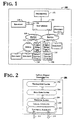
- Fig. 1 is a block diagram of a simplified electronic appliance 100 incorporating an enhanced general input/output (EGIO) bus architecture, protocol and related methods, in accordance with the teachings of the present invention.
- electronic appliance 100 is depicted comprising one or more of processor(s) 102, a host bridge 104, switches 108 and end-points 110, each coupled as shown.
- processor(s) 102 processor(s) 102
- host bridge 104 switches 108 and end-points 110
- at least host bridge 104, switch(es) 108, and end-points 110 are endowed with one or more instances of an EGIO communication interface 106 to facilitate one or more aspects of the present invention.
- each of the elements 102, 104, 108 and 110 are communicatively coupled to at least one other element through a communication link 112 supporting one or more EGIO communication channel(s) via the EGIO interface 106.
- electronic appliance 100 is intended to represent one or more of any of a wide variety of traditional and non-traditional computing systems, servers, network switches, network routers, wireless communication subscriber units, wireless communication telephony infrastructure elements, personal digital assistants, set-top boxes, or any electric appliance that would benefit from the communication resources introduced through integration of at least a subset of the EGIO interconnection architecture, communications protocol or related methods described herein.
- processor(s) 102 control one or more aspects of the functional capability of the electronic appliance 100.
- processor(s) 102 are representative of any of a wide variety of control logic including, but not limited to one or more of a microprocessor, a programmable logic device (PLD), programmable logic array (PLA), application specific integrated circuit (ASIC), a microcontroller, and the like.
- Host bridge 104 provides a communication interface between processor 102 and/or a processor/memory complex and one or more other elements 108, 110 of the electronic appliance EGIO architecture and is, in this regard, the root of the EGIO architecture hierarchy.
- a host bridge 104 refers to a logical entity of an EGIO hierarchy that is closest to a host controller, a memory controller hub, an IO controller hub, or any combination of the above, or some combination of chipset/CPU elements (i.e., in a computing system environment).
- Fig. 1 although depicted in Fig. 1 as a single unit, host bridge 104 may well be thought of as a single logical entity that may well have multiple physical components. According to the illustrated example implementation of Fig.
- host bridge 104 is populated with one or more EGIO interface(s) 106 to facilitate communication with other peripheral devices, e.g., switch(es) 108, end-point(s) 110 and, although not particularly depicted, legacy bridge(s) 114, or 116.
- each EGIO interface 106 represents a different EGIO hierarchy domain.
- the illustrated implementation of Fig. 1 denotes a host bridge 104 with three (3) hierarchy domains It should be noted that although depicted as comprising multiple separate EGIO interfaces 106, alternate implementations are anticipated wherein a single interface 106 is endowed with multiple ports to accommodate communication with multiple devices.
- switches 108 have at least one upstream port (i.e., directed towards the host bridge 104), and at least one downstream port.
- a switch 108 distinguishes one port (i.e., a port of an interface or the interface 106 itself) which is closest to the host bridge as the upstream port, while all other port(s) are downstream ports.
- switches 108 appear to configuration software (e.g., legacy configuration software) as a PCI-to-PCI bridge, and use PCI bridge mechanisms for routing transactions.
- switches 108 In the context of switches 108, peer-to-peer transactions are defined as transactions for which the receive port and the transmitting port are both downstream ports. According to one implementation, switches 108 support routing of all types of transaction layer packets (TLP) except those associated with a locked transaction sequence from any port to any other port. In this regard, all broadcast messages should typically be routed from the receiving port to all other ports on the switch 108. A transaction layer packet which cannot be routed to a port should typically be terminated as an unsupported TLP by the switch 108.
- TLP transaction layer packets
- Switches 108 typically do not modify transaction layer packet(s) (TLP) when transferring them from the receiving port to the transmitting port unless modification is required to conform to a different protocol requirement for the transmitting port (e.g., transmitting port coupled to a legacy bridge 114, 116).
- TLP transaction layer packet(s)
- switches 108 act on behalf of other devices and, in this regard, do not have advance knowledge of traffic types and patterns.
- the flow control and data integrity aspects of the present invention are implemented on a per-link basis, and not on an end-to-end basis.
- switches 108 participate in protocols used for flow control and data integrity.
- switch 108 maintains a separate flow control for each of the ports to improve performance characteristics of the switch 108.
- switch 108 supports data integrity processes on a per-link basis by checking each TLP entering the switch using the TLP error detection mechanisms, described more fully below.
- downstream ports of a switch 108 are permitted to form new EGIO hierarchy domains.
- an end-point 110 is defined as any device with a Type 00hex (00h) configuration space header.
- End-point devices 110 can be either a requester or a completer of an EGIO semantic transaction, either on its own behalf or on behalf of a distinct non-EGIO device.
- Examples of such end-points 110 include, but are not limited to, EGIO compliant graphics device(s), EGIO-compliant memory controller, and/or devices that implement a connection between EGIO and some other interface such as a universal serial bus (USB), Ethernet, and the like.
- USB universal serial bus
- an end-point 110 acting as an interface for non-EGIO compliant devices may well not provide full software support for such non-EGIO compliant devices. While devices that connect a host processor complex 102 to an EGIO architecture are considered a host bridge 104, it may well be the same device type as other end-points 110 located within the EGIO architecture distinguished only by its location relative to the processor complex 102.
- end-points 110 may be lumped into one or more of three categories, (1) legacy and EGIO compliant end-points, (2) legacy end-points, and (3) EGIO compliant end-points, each having different rules of operation within the EGIO architecture.
- EGIO compliant end-points 110 are distinguished from legacy end-points (e.g., 118, 120) in that an EGIO end-point 110 will have a type 00h configuration space header. Either of such end-points (110, 118 and 120) support configuration requests as a completer. Such end-points are permitted to generate configuration requests, and may be classified as either a legacy end-point or as an EGIO compliant end-point, but such classification may well require adherence to the following additional rules.
- Legacy end-points e.g., 118, 120 are permitted to support IO requests as a completer and are permitted to generate IO requests.
- Legacy end-points (118, 120) are permitted to generate lock semantics as completers if that is required by their legacy software support requirements.
- Legacy end-points typically do not issue a locked request.
- EGIO compliant end-points 110 typically do not support IO requests as a completer and do not generate IO requests. EGIO end-points 110 do not support locked requests as a completer, and do not generate locked requests as a requester.
- EGIO to Legacy bridges 114, 116 are specialized end-points 110 that include substantial software support, e.g., full software support, for the legacy devices (118, 120) they interface to the EGIO architecture.
- a legacy bridge 114, 116 typically has one upstream port (but may have more), with multiple downstream ports (but may just have one). Locked requests are supported in accordance with the legacy software model.
- An upstream port of a legacy bridge 114, 116 should support flow control on a per-link basis and adhere to the flow control and data integrity rules of the EGIO architecture, developed more fully below.
- link 112 is intended to represent any of a wide variety of communication media including, but not limited to, copper lines, optical lines, wireless communication channel(s), an infrared communication link, and the like.
- an EGIO link 112 is a differential pair of serial lines, one pair each to support transmit and receive communications, thereby providing support for full-duplex communication capability.
- the link provides a scalable serial clocking frequency with an initial (base) operating frequency of 2.5GHz.
- the interface width, per direction, is scalable from x1, x2, x4, x8, x12, x16, x32 physical lanes.
- EGIO link 112 may well support multiple virtual channels between devices thereby providing support for uninterrupted communication of isochronous traffic between such devices using one or more virtual channels, e.g., one channel for audio and one channel for video.
- Fig. 2 is a graphical illustration of an example EGIO interface 106 architecture employed by one or more elements of the electronic appliance to facilitate communication between such elements, according to one example embodiment of the present invention.
- the EGIO interface 106 may well be represented as a communication protocol stack comprising a transaction layer 202, a data link layer 204 and a physical layer 208.
- the physical link layer interface is depicted comprising a logical sub-block 210, and a physical sub-block, as shown, each of which will be developed more fully below.
- the transaction layer 202 provides an interface between the EGIO architecture and a device core.
- a primary responsibility of the transaction layer 202 is the assembly and disassembly of packets (i.e., transaction layer packets, or TLPs) for one or more logical devices within a host device (or, agent).
- Transactions form the basis for information transfer between an initiator agent and a target agent.
- four address spaces are defined within the innovative EGIO architecture including, for example, a configuration address space, a memory address space, an input/output address space, and a message address space, each with its own unique intended usage (see, e.g., Fig. 7, developed more fully below).
- Memory space (706) transactions include one or more of read requests and write requests to transfer data to/from a memory-mapped location.
- Memory space transactions may use two different address formats, e.g., a short address format (e.g., 32-bit address) or a long address format (e.g., 64-bits long).
- the EGIO architecture provides for conventional read, modify, and write sequences using lock protocol semantics (i.e., where an agent may well lock access to modified memory space). More particularly, support for downstream locks are permitted, in accordance with particular device rules (bridge, switch, end-point, legacy bridge). As introduced above, such lock semantics are supported in the support of legacy devices.
- IO space (704) transactions are used to access input/output mapped memory registers within a IO address space (e.g., an 16-bit IO address space).
- IO address space e.g., an 16-bit IO address space.
- processors 102 such as Intel Architecture processors, and others, include n IO space definition through the processor's instructions set. Accordingly, IO space transactions include read requests and write requests to transfer data from/to an IO mapped location.
- Configuration space (702) transactions are used to access configuration space of the EGIO devices. Transactions to the configuration space include read requests and write requests. In as much as conventional processors do not typically include a native configuration space, this space is mapped through a mechanism that is software compatible with convention PCI configuration space access mechanisms (e.g., using CFC/CFC8-based PCI configuration mechanism #1). Alternatively, a memory alias mechanism may well be used to access configuration space.
- Message space (708) transactions are defined to support in-band communication between EGIO agents through interface(s) 106.
- Conventional processors do not include support for native message space, so this is enabled through EGIO agents within the EGIO interface 106.
- traditional "side-band" signals such as interrupts and power management requests are implemented as messages to reduce the pin count required to support such legacy signals.
- Some processors, and the PCI bus include the concept of "special cycles," which are also mapped into messages within the EGIO interface 106.
- messages are generally divided into two categories: standard messages and vendor-defined messages.
- standard messages include a general-purpose message group and a system management message group.
- General-purpose messages may be a single destination message or a broadcast/multicast message.
- the system management message group may well consist of one or more of interrupt control messages, power management messages, ordering control primitives, and error signaling, examples of which are introduced below.
- the general purpose messages include messages for support of locked transaction.
- an UNLOCK message is introduced, wherein switches (e.g., 108) should typically forward the UNLOCK message through any port which may be taking part in a locked transaction.
- End-point devices e.g., 110, 118, 120 which receive an UNLOCK message when they are not locked will ignore the message. Otherwise, locked devices will unlock upon receipt of an UNLOCK message.
- the system management message group includes special messages for ordering and synchronization messages.
- One such message is a FENCE message, to impose strict ordering rules on transactions generated by receiving elements of the EGIO architecture.
- FENCE messages are only reacted to by a select subset of network elements, e.g., end-points.
- messages denoting a correctable error, uncorrectable error, and fatal errors are anticipated herein, e.g., through the use of tailer error forwarding.
- the system management message group provides for signaling of interrupts using in-band messages.
- the ASSERT_INTx/DEASSERT_INTx message pair is introduced wherein issuing of the assert interrupt message is sent to the processor complex through host bridge 104.
- usage rules for the ASSERT_INTx/DEASSERT_INTx message pair mirrors that of the PCI INTx# signals found in the PCI specification, introduced above. From any one device, for every transmission of Assert_INTx, there should typically be a corresponding transmission of Deassert_INTx.
- Switches should typically route Assert_INTx/Deassert_INTx messages to the Host Bridge 104, wherein the Host Bridge should typically track Assert_INTx/Deassert_INTx messages to generate virtual interrupt signals and map these signals to system interrupt resources.
- the EGIO architecture establishes a standard framework within which core-logic (e.g., chipset) vendors can define their own vendor-defined messages tailored to fit the specific operating requirements of their platforms.
- This framework is established through a common message header format where encodings for vendor-defined messages are defined as "reserved”.
- a transaction descriptor is a mechanism for carrying transaction information from the origination point, to the point of service, and back. It provides an extensible means for providing a generic interconnection solution that can support new types of emerging applications.
- the transaction descriptor supports identification of transactions in the system, modifications of default transaction ordering, and association of transaction with virtual channels using the virtual channel ID mechanism.
- a graphical illustration of a transaction descriptor is presented with reference to Fig. 3.
- a graphical illustration of a datagram comprising an example transaction descriptor is presented, in accordance with the teachings of the present invention.
- the transaction descriptor 300 is presented comprising a global identifier field 302, an attributes field 306 and a virtual channel identifier field 308.
- the global identifier field 302 is depicted comprising a local transaction identifier field 308 and a source identifier field 310.
- the global transaction identifier is unique for all outstanding requests.
- the global transaction identifier 302 consists of two sub-fields: the local transaction identifier field 308 and a source identifier field 310.
- the local transaction identifier field 308 is an eight-bit field generated by each requestor, and it is unique for all outstanding requests that require a completion for that requestor.
- the source identifier uniquely identifies the EGIO agent within the EGIO hierarchy. Accordingly, together with source ID the local transaction identifier field provides global identification of a transaction within a hierarchy domain.
- the local transaction identifier 308 allows requests/completions from a single source of requests to be handled out of order (subject to the ordering rules developed more fully below). For example, a source of read requests can generate reads A1 and A2. The destination agent that services these read requests may return a completion for request A2 transaction ID first, and then a completion for A1 second. Within the completion packet header, local transaction ID information will identify which transaction is being completed. Such a mechanism is particularly important to appliances that employ distributed memory systems since it allows for handling of read requests in a more efficient manner. Note that support for such out-of-order read completions assumes that devices that issue read requests will ensure pre-allocation of buffer space for the completion. As introduced above, insofar as EGIO switches 108 are not end-points (i.e., merely passing completion requests to appropriate end-points) they need not reserve buffer space.
- a single read request can result in multiple completions. Completions belonging to single read request can be returned out-of-order with respect to each other. This is supported by providing the address offset of the original request that corresponds to partial completion within a header of a completion packet (i.e., completion header).
- the source identifier field 310 contains a 16-bit value that is unique for every logical EGIO device. Note that a single EGIO device may well include multiple logical devices.
- the source ID value is assigned during system configuration in a manner transparent to the standard PCI bus enumeration mechanism.
- EGIO devices internally and autonomously establish a source ID value using, for example, bus number information available during initial configuration accesses to those devices, along with internally available information that indicates, for example, a device number and a stream number.
- bus number information is generated during EGIO configuration cycles using a mechanism similar to that used for PCI configuration.
- the bus number is assigned by a PCI initialization mechanism and captured by each device. In the case of Hot Plug and Hot Swap devices, such devices will need to re-capture this bus number information on every configuration cycle access to enable transparency to SHPC software stacks.
- a physical component may well contain one or more logical devices (or, agents). Each logical device is designed to respond to configuration cycles targeted at its particular device number, i.e., the notion of device number is embedded within the logical device. According to one implementation, up to sixteen logical devices are allowed in a single physical component. Each of such logical devices may well contain one or more streaming engines, e.g., up to a maximum of sixteen. Accordingly, a single physical component may well comprise up to 256 streaming engines.
- Transactions tagged by different source identifiers belong to different logical EGIO input/output (IO) sources and can, therefore, be handled completely independently from each other from an ordering point of view.
- IO input/output
- a fence ordering control primitive can be used to force ordering if necessary.
- the global transaction identifier field 302 of the transaction descriptor 300 adheres to at least a subset of the following rules:
- the attributes field 304 specifies characteristics and relationships of the transaction.
- the attributes field 304 is used to provide additional information that allows modification of the default handling of transactions. These modifications may apply to different aspects of handling of the transactions within the system such as, for example, ordering, hardware coherency management (e.g., snoop attributes) and priority.
- An example format for the attributes field 304 is presented with sub-fields 312-318.
- the attribute field 304 includes a priority sub-field 312.
- the priority sub-field may be modified by an initiator to assign a priority to the transaction.
- class or quality of service characteristics of a transaction or an agent may be embodied in the priority sub-field 312, thereby affecting processing by other system elements.
- the reserved attribute field 314 is left reserved for future, or vendor-defined usage. Possible usage models using priority or security attributes may be implemented using the reserved attribute field.
- the ordering attribute field 316 is used to supply optional information conveying the type of ordering that may modify default ordering rules within the same ordering plane (where the ordering plane encompasses the traffic initiated by the host processor (102) and the IO device with its corresponding source ID).
- an ordering attribute of "0" denotes default ordering rules are to apply, wherein an ordering attribute of "1" denotes relaxed ordering, wherein writes can pass writes in the same direction, and read completions can pass writes in the same direction.
- devices that use relaxed ordering semantics primarily for moving the data and transactions with default ordering for reading/writing status information.
- the snoop attribute field 318 is used to supply optional information conveying the type of cache coherency management that may modify default cache coherency management rules within the same ordering plane, wherein an ordering plane encompasses traffic initiated by a host processor 102 and the IO device with its corresponding source ID).
- a snoop attribute field 318 value of "0" corresponds to a default cache coherency management scheme wherein transactions are snooped to enforce hardware level cache coherency.
- a value of "1" in the snoop attribute field 318 suspends the default cache coherency management schemes and transactions are not snooped. Rather, the data being accessed is either non-cacheable or its coherency is being managed by software.
- the virtual channel ID field 306 identifies an independent virtual channel to which the transaction is associated.
- the virtual channel identifier is a four-bit field that allows identification of up to sixteen virtual channels (VCs) on a per-transaction basis.
- the transaction layer 202 of the EGIO interface 106 can establish one or more virtual channels within the bandwidth of the communication link 112.
- the virtual channel (VC) aspect of the present invention is used to define separate, logical communication interfaces within a single physical EGIO link 112.
- separate VCs are used to map traffic that would benefit from different handling policies and servicing priorities. For example, traffic that requires deterministic quality of service, in terms of guaranteeing X amount of data transferred within T period of time, can be mapped to an isochronous (time dependent) virtual channel. Transactions mapped to different virtual channels may not have any ordering requirements with respect to each other. That is, virtual channels operate as separate logical interfaces, having different flow control rules and attributes.
- VCs comprehend the following two types of traffic: general purpose IO traffic, and Isochronous traffic. That is, in accordance with this example implementation, two types of virtual channels are described: (1) general purpose IO virtual channels, and (2) isochronous virtual channels.
- transaction layer 202 maintains independent flow control for each of the one or more virtual channel(s) actively supported by the component.
- all EGIO compliant components should typically support the general IO type virtual channel, e.g., virtual channel 0, where there are no ordering relationships required between disparate virtual channels of this type.
- VC 0 is used for general purpose IO traffic
- VC 1 is assigned to handle Isochronous traffic.
- any virtual channel may be assigned to handle any traffic type.
- a graphical illustration of an example EGIO link 112 is presented comprising multiple virtual channels (VC), according to one aspect of the present invention.
- EGIO link 112 is presented comprising multiple virtual channels 402, 404 created between EGIO interface(s) 106.
- traffic from multiple sources 406A...N are illustrated, differentiated by at least their source ID.
- virtual channel 402 was established with no ordering requirements between transactions from different sources (e.g., agents, interfaces, etc.).
- virtual channel 404 is presented comprising traffic from multiple sources multiple transactions 408A...N wherein each of the transactions are denoted by at least a source ID.
- transactions from source ID 0 406A are strongly ordered unless modified by the attributes field 304 of the transaction header, while the transactions from source 408N depict no such ordering rules.
- An example method of establishing and managing virtual channel(s) is presented with reference to Fig. 10, below.
- transaction layer 202 attempts to improve performance by permitting transaction re-ordering.
- transaction layer 202 "tags" transactions. That is, according to one embodiment, transaction layer 202 adds a transaction descriptor to each packet such that its transmit time may be optimized (e.g., through re-ordering) by elements in the EGIO architecture, without losing track of the relative order in which the packet was originally processed.
- Such transaction descriptors are used to facilitate routing of request and completion packets through the EGIO interface hierarchy.
- the transaction layer 202 employs a set of rules to define the ordering requirements for EGIO transactions.
- Transaction ordering requirements are defined to ensure correct operation with software designed to support the producer-consumer ordering model while, at the same time, allowing improved transaction handling flexibility for application based on different ordering models (e.g., relaxed ordering for graphics attach applications). Ordering requirements for two different types of models are presented below, a single ordering plane model and a multiple ordering plane model.
- a memory control hub that provides an interface to a host processor and a memory subsystem
- an IO control hub that provides interface to an IO subsystem.
- Both hubs contain internal queues that handle inbound and outbound traffic and in this simple model all 10 traffic is mapped to a single "ordering plane".
- Transaction Descriptor Source ID information provides a unique identification for each Agent within an EGIO Hierarchy.
- IO traffic mapped to the Source ID can carry different Transaction ordering attributes). Ordering rules for this system configuration are defined between IO-initiated traffic and host- initiated traffic. From that perspective IO traffic mapped to a Source ID together with host processor initiated traffic represent traffic that is conducted within a single "ordering plane”.
- Table II An example of such transaction ordering rules are provided below with reference to Table II.
- the rules defined in this table apply uniformly to all types of Transactions in the EGIO system including Memory, IO, Configuration and Messages.
- Table II below, the columns represent the first of two Transactions, and the rows represent the second.
- the table entry indicates the ordering relationship between the two Transactions.
- the table entries are defined as follows:
- the previous section defined ordering rules within a single "ordering plane".
- the EGIO interconnection architecture and communication protocol employs a unique Transaction Descriptor mechanism to associate additional information with a Transaction to support more sophisticated ordering relationships.
- Fields in the Transaction Descriptor allow the creation of multiple "ordering planes" that are independent of each other from an IO traffic ordering point of view.
- Each "ordering plane” consists of queuing/buffering logic that corresponds to a particular IO device (designated by a unique Source ID) and of queuing/buffering logic that carries host processor initiated traffic.
- the ordering within the "plane” is typically defined only between these two.
- the plane mapping mechanism permits the existence of multiple ordering planes, some or all of the ordering planes can be "collapsed" together to simplify the implementation (i.e. combining multiple separately controlled buffers/FIFOs into a single one).
- the Transaction Descriptor Source ID mechanism is used only to facilitate routing of Transactions and it is not used to relax ordering between independent streams of IO traffic.
- the transaction descriptor mechanism provides for modifying default ordering within a single ordering plane using an ordering attribute. Modifications of ordering can, therefore, be controlled on per-transaction basis.
- the innovative EGIO architecture uses a packet based protocol to exchange information between transaction layers of two devices that communicate with one another.
- the EGIO architecture generally supports the Memory, IO, Configuration and Messages transaction types. Such transactions are typically carried using request or completion packets, wherein completion packets are only used when required, i.e., to return data or to acknowledge receipt of a transaction.
- TLP header 600 is presented comprising a format field, a type field, an extended type/extended length (ET/EL) field, and a length field.
- TLPs include data following the header as determined by the format field specified in the header.
- No TLP should include more data than the limit set by MAX_PAYLOAD_SIZE.
- TLP data is four-byte naturally aligned and in increments of a four-byte double word (DW).
- the format (FMT) field specifies the format of the TLP, in accordance with the following definitions:
- the TYPE field is used to denote the type encodings used in the TLP. According to one implementation, both Fmt[2:0] and Type[3:0] should typically be decoded to determine the TLP format. According to one implementation, the value in the type[3:0] field is used to determine whether the extended type/extended length field is used to extend the Type field or the Length field. The ET/EL field is typically only used to extend the length field with memory-type read requests.
- the length field provides an indication of the length of the payload, again in DW increments of:
- TLP Type FMT Type Et Description [2:0] [3:0] [1:0]
- Initial FCP 000 0000 00 Initial flow control information Update FCP 000 0001 00
- MRdLK 001 1011 Memory read request - locked 010 MWR 101 0001 00
- Memory Write request - posted 110 IORd 001 1010 00 IO Read request IOWr 101 1010 00 IO Write request CfgRd0 001 1010 01 Configuration read type 0 CfgWr0 101 1010 01 Configuration write type 0 CfgRd1 001 1010 11 Configuration read type 1 CfgWr1 101 1010 11 Configuration write type 1 Msg 010 011s2 s1s0 Message request - the sub-field s
- the message field is decoded to determine specific cycle including if a completion is required MsgD 110 001s2 s1s0 Message request with data-the sub-field s[2:0] specify a group of messages.
- the message field is decoded to determine specific cycle including if a completion is required MsgCR 010 111s2 s1s0 Message request completion required - The sub-fields s[2:0] specify a group of messages.
- the message field is decoded to determine specific cycle MsgDCR 110 111s2 sls0 Message request with data completion required -
- the sub-fields s[2:0] specify a group of messages.
- the Special Cycle field is decided to determine specific cycle.
- CPL 001 0100 00 Completion without data-used for IO and configuration write completions, some message completions, and memory read completions with completion status other than successful completion.
- CpID 101 0100 00 Completion with data-used for memory, IO, and configration read completions, and some message completions.
- Cp1DLk 101 001 01 Completion for locked memory read- otherwise like Cp1D
- the transaction layer 202 of the EGIO interface 106 includes a flow control mechanism that proactively reduces the opportunity for overflow conditions to arise, while also providing for adherence to ordering rules on a per-link basis of the virtual channel established between the initiator and the completer(s).
- a flow control "credit" is introduced, wherein a receiver shares information about (a) the size of the buffer (in credits), and (b) the currently available buffer space with a transmitter for each of the virtual channel(s) established between the transmitter and the receiver (i.e., on a per-virtual channel basis).
- an estimate of the available buffer space e.g., a count of available credits
- the transaction layer 202 introduces flow control to prevent overflow of receiver buffers and to enable compliance with the ordering rules, introduced above.
- the flow control mechanism of the transaction layer 202 is used by a requester to track the queue/buffer space available in an agent across the EGIO link 112. As used herein, flow control does not imply that a request has reached its ultimate completer.
- flow control is orthogonal to the data integrity mechanisms used to implement reliable information exchange between a transmitter and a receiver. That is, flow control can treat the flow of transaction layer packet (TLP) information from transmitter to receiver as perfect, since the data integrity mechanisms ensure that corrupted and lost TLPs are corrected through retransmission.
- TLP transaction layer packet
- the flow control comprehends the virtual channels of the EGIO link 112. In this regard, each virtual channel supported by a receiver will be reflected in the flow control credits (FCC) advertised by the receiver.
- FCC flow control credits
- flow control is performed by the transaction layer 202 in cooperation with the data link layer 204.
- the following types of packet information is distinguished:
- a flow control credit is 16 bytes for data.
- the unit of flow control credit is one header.
- each virtual channel has independent flow control. For each virtual channel, separate indicators of credits are maintained and tracked for each of the foregoing types of packet information ((a)-(f), as denoted above).
- transmission of packets consume flow control credits in accordance with the following:
- the credits consumed register includes a count of the total number of flow control units modula 256 consumed since initialization.
- the credits consumed register is set to all zeros (0) and incremented as the transaction layer commits to sending information to the data link layer.
- the size of the increment is associated with the number of credits consumed by the information committed to be sent.
- the maximum count e.g., all 1's
- the counter rolls over to zero.
- unsigned 8bit module arithmetic is used to maintain the counter.
- the credit limit register contains the limit for the maximum number of flow control units which may be consumed. Upon interface initialization, the register is set to all zeros, and is set to the value indicated in an flow control update message (introduced above) upon message receipt.
- the credits allocated register maintains a count of the total number of credits granted to the transmitter since initialization.
- the count is initially set according to the buffer size and allocation policies of the receiver. This value may well be included in flow control update messages.
- the value is incremented as the receiver transaction layer removes processed information from its receive buffer. The size of the increment is associated with the size of the space made available. According to one embodiment, receivers should typically initially set the credits allocated to values equal to or greater than the following values:
- a transmitter can dynamically calculate the credits allocated in accordance with the following equation:
- C_A Credit unit number of the most recently received transmission + receive buffer space available
- a transmitter implement the conceptual registers (credit consumed, credit limit) for each of the virtual channels which the transmitter will utilize.
- receivers implement the conceptual registers (credits allocated) for each of the virtual channels supported by the receiver.
- a transmitter is permitted to transmit a type of information if the credits consumed count plus the number of credit units associate with the data to be transmit is less than or equal to the credit limit value.
- CPLs flow control information for completions
- the transmitter will throttle completions according to the credit available.
- a receiver if a receiver receives more information than it has allocated credits for (exceeding the credits allocated) the receiver will indicate a receiver overflow error to the offending transmitter, and initiate a data link level retry request for the packet causing the overflow.
- the flow control information necessary to maintain the registers is communicated between devices using flow control packets (FCPs).
- FCPs flow control packets
- flow control packets are comprised of two-DW Header format and convey information for a specific Virtual Channel about the status of the six Credit registers maintained by the Flow Control logic of the Receive Transaction Layer for each VC.
- FCPs there are two types of FCPs: Initial FCP and Update FCP, as illustrated in Fig. 6.
- an initial FCP 602 is issued upon initialization of the Transaction Layer.
- Update FCPs 604 are used to update information in the registers. Receipt of an Initial FCP during normal operation causes a reset of the local flow control mechanism and the transmission of an Initial FCP.
- the content of an Initial FCP includes at least a subset of the advertised credits for each of the PRH, PRD, NPRH, NPRD, CPH, CPD, and Channel ID (e.g., the Virtual channel associated to which FC information applies).
- the format of an Update FCP is similar to that of the Initial FCP. Note that although the FC Header does not include the Length field common other transaction layer packet header format, the size of the Packet is unambiguous because there is no additional DW data associated with this Packet.
- the EGIO architecture relies on tailer information, appended to datagram(s) identified as defective for any of a number of reasons, as discussed below.
- the transaction layer 202 employs any of a number of well-known error detection techniques such as, for example, cyclical redundancy check (CRC) error control and the like.
- CRC cyclical redundancy check
- the EGIO architecture uses a "tailer", which is appended to TLPs carrying known bad data. Examples of cases in which tailer Error Forwarding might be used include:
- error forwarding is only used for read completion data, or the write data. That is, error forwarding is not typically employed for cases when the error occurs in the administrative overhead associated with the datagram, e.g., an error in the header (e.g., request phase, address/command, etc.).
- an error in the header e.g., request phase, address/command, etc.
- requests/completions with header errors cannot be forwarded in general since a true destination cannot be positively identified and, therefore, such error forwarding may well cause a direct or side effects such as, fore example data corruption, system failures, etc.
- error forwarding is used for propagation of error through the system, system diagnostics.
- Error forwarding does not utilize data link layer retry and, thus TLPs ending with the tailer will be retried only if there are transmission errors on the EGIO link 112 as determined by the TLP error detection mechanisms (e.g., cyclical redundancy check (CRC), etc.).
- the tailer may ultimately cause the originator of the request to reissue it (at the transaction layer of above) or to take some other action.
- all EGIO receivers are able to process TLPs ending with a tailer.
- Support for adding a tailer in a transmitter is optional (and therefore compatible with legacy devices).
- Switches 108 route a tailer along with the rest of a TLP.
- Host Bridges 104 with peer routing support will typically route a tailer along with the rest of a TLP, but are not required to do so.
- Error Forwarding typically applies to the data within a Write Request (Posted or Non-Posted) or a Read Completion. TLPs which are known to the transmitter to include bad data should end with the tailer.
- a tailer consists of two DW, wherein bytes [7:5] are all zeroes (e.g., 000), and bits [4:1] are all ones (e.g., 1111), while all other bits are reserved.
- An EGIO receiver will consider all the data within a TLP ending with the tailer corrupt.
- the receiver will cause all data from the indicated TLP to be tagged as bad ("poisoned").
- a parser will typically parse to the end of the entire TLP and check immediately the following data to understand if the data completed or not.
- the data link layer 204 of Fig. 2 acts as an intermediate stage between the Transaction Layer 202 and the Physical Layer 206.
- the primary responsibility of the data link layer 204 is providing a reliable mechanism for exchanging Transaction Layer Packets (TLPs) between two components over an EGIO Link 112.
- TLPs Transaction Layer Packets
- the transmission side of the Data Link Layer 204 accepts TLPs assembled by the Transaction Layer 202, applies a Packet Sequence Identifier (e.g., an identification number), calculates and applies an error detection code (e.g., CRC code), and submits the modified TLPs to the Physical Layer 206 for transmission across a select one or more of the virtual channels established within the bandwidth of the EGIO Link 112.
- a Packet Sequence Identifier e.g., an identification number
- CRC code error detection code
- the receiving Data Link Layer 204 is responsible for checking the integrity of received TLPs (e.g., using CRC mechanisms, etc.) and for submitting those TLPs for which the integrity check was positive to the Transaction Layer 204 for disassembly before forwarding to the device core.
- Services provided by the Data Link Layer 204 generally include data exchange, error detection and retry, initialization and power management services, and data link layer inter-communication services. Each of the services offered under each of the foregoing categories are enumerated below.
- the Data Link Layer 204 appears as an information conduit with varying latency to the Transaction Layer 202. All information fed into the Transmit Data Link Layer will appear at the output of the Receive Data Link Layer at a later time. The latency will depend on a number of factors, including pipeline latencies, width and operational frequency of the Link 112, transmission of communication signals across the medium, and delays caused by Data Link Layer Retry. Because of these delays, the Transmit Data Link Layer can apply backpressure to the Transmit Transaction Layer 202, and the Receive Data Link Layer communicates the presence or absence of valid information to the Receive Transaction Layer 202.
- the data link layer 204 tracks the state of the EGIO link 112.
- the DLL 204 communicates Link status with the Transaction 202 and Physical Layers 206, and performs Link Management through the Physical Layer 206.
- the Data Link Layer contains a Link Control and Management State Machine to perform such management tasks. The states for this machine are described below:
- DLLPs data link layer packets
- the EGIO architecture provides for the following DLLPs to support link data integrity management:
- the transaction layer 202 provides TLP boundary information to Data Link Layer 204, enabling the DLL 204 to apply a Sequence Number and cyclical redundancy check (CRC) error detection to the TLP.
- CRC cyclical redundancy check
- the Receive Data Link Layer validates received TLPs by checking the Sequence Number, CRC code and any error indications from the Receive Physical Layer. In case of error in a TLP, Data Link Layer Retry is used for recovery.
- TLP is corrupted on the Link 112 such that the Receiver does not detect the existence of the TLP.
- the lost TLP will be detected when a following TLP is sent because the TLP Sequence Number will not match the expected Sequence Number at the Receiver.
- the Transmit Data Link Layer 204 cannot in general bound the time for the next TLP to be presented to it from the Transmit Transport Layer.
- the Ack Timeout mechanism allows the Transmitter to bound the time required for the Receiver to detect the lost TLP.
- the physical layer 206 is presented. As used herein, the physical layer 206 isolates the transaction 202 and data link 204 layers from the signaling technology used for link data interchange. In accordance with the illustrated example implementation of Fig. 2, the Physical Layer is divided into the logical 208 and physical 210 functional sub-blocks.
- the logical sub-block 208 is responsible for the "digital" functions of the Physical Layer 206.
- the logical sub-block 204 has two main divisions: a Transmit section that prepares outgoing information for transmission by the physical sub-block 210, and a Receiver section that identifies and prepares received information before passing it to the Link Layer 204.
- the logical sub-block 208 and physical sub-block 210 coordinate the Port state through a status and control register interface. Control and management functions of the Physical Layer 206 are directed by the logical sub-block 208.
- the EGIO architecture employs an 8b/10b transmission code. Using this scheme, eight-bit characters are treated as three-bits and five-bits mapped onto a four-bit code group and a six-bit code group, respectivley. These code groups are concatenated to form a ten-bit Symbol.
- the 8b/10b encoding scheme used by EGIO architecture provides Special Symbols which are distinct from the Data Symbols used to represent Characters. These Special Symbols are used for various Link Management mechanisms below. Special Symbols are also used to frame DLLPs and TLPs, using distinct Special Symbols to allow these two types of Packets to be quickly and easily distinguished.
- the physical sub-block 210 contains a Transmitter and a Receiver.
- the Transmitter is supplied by the Logical sub-block 208 with Symbols which it serializes and transmits onto the Link 112.
- the Receiver is supplied with serialized Symbols from the Link 112. It transforms the received signals into a bit-stream which is de-serialized and supplied to the Logical sub-block 208 along with a Symbol clock recovered from the incoming serial stream.
- the EGIO link 112 may well represent any of a wide variety of communication media including an electrical communication link, an optical communication link, an RF communication link, an infrared communication link, a wireless communication link, and the like.
- each of the transmitter(s) and/or receiver(s) comprising the physical sub-block 210 of the physical layer 206 is appropriate for one or more of the foregoing communication links.
- Fig. 5 illustrates a block diagram of an example communication agent incorporating at least a subset of the features associated with the present invention, in accordance with one example implementation of the present invention.
- communications agent 500 is depicted comprising control logic 502, an EGIO communication engine 504, memory space for data structures 506 and, optionally one or more applications 508.
- control logic 502 provides processing resources to each of the one or more elements of EGIO communication engine 504 to selectively implement one or more aspects of the present invention.
- control logic 502 is intended to represent one or more of a microprocessor, a microcontroller, a finite state machine, a programmable logic device, a field programmable gate array, or content which, when executed, implements control logic to function as one of the above.
- EGIO communication engine 504 is depicted comprising one or more of a transaction layer interface 202, a data link layer interface 204 and a physical layer interface 206 comprising a logical sub-block 208 and a physical sub-block 210 to interface the communication agent 500 with an EGIO link 112.
- the elements of EGIO communication engine 504 perform function similar, if not equivalent to, those described above.
- communications agent 500 is depicted comprising data structures 506.
- data structures 506 may well include memory space, IO space, configuration space and message space utilized by communication engine 504 to facilitate communication between electronic appliance devices.
- applications 508 are intended to represent any of a wide variety of applications selectively invoked by communication engine 500 to implement the EGIO communication protocol and associated management functions.
- Fig. 7 a graphical illustration of one or more data structure(s) employed by EGIO interface(s) 106 are depicted, in accordance with one implementation of the present invention. More particularly, with reference to the illustrated example implementation of Fig. 7, four (4) address spaces are defined for use within the EGIO architecture: the configuration space 710, the IO space 720, the memory space 730 and the message space 740. As shown, configuration space 710 includes a header field 712, which defines the EGIO category to which a host device belongs (e.g., end-point, etc.). Each of such address spaces perform their respective functions as detailed above.
- FIG. 10 a flow chart of an example method of managing the physical communication resources of the enhanced general input/output architecture is presented.
- a flow chart of an example method of establishing an managing one or more virtual channel(s) within the physical resources of the enhanced general input/output link is presented, in accordance with one example embodiment of the present invention.
- the method begins with block 1002 wherein an EGIO interface 106 receives information for transmission to another component.
- the transaction layer 202 of an EGIO interface 106 receives the information from a processing agent within a host component.
- the EGIO interface 106 determines whether the received information is associated with an established virtual channel, or whether a new virtual channel is required. According to one implementation, transaction layer 202 makes such a determination by identifying the source and destination of the information. If, in block 1004 transaction layer 202 identifies the information as associated with an existing virtual channel, transaction layer 202 generates transaction layer packets (TLP) associated with the appropriate virtual channel to communicate the received information through the physical link layer 206 to the appropriate virtual channel for transmission over the physical general input/output resources, block 1006.
- TLP transaction layer packets
- transaction layer 202 makes a further determination as to the type of virtual channel required, block 1008. According to one example implementation, transaction layer 202 makes this determination based, at least in part, on the content of the received information. According to one example implementation, introduced above, the EGIO architecture provides support for multiple types of virtual channels selected based on the quality-of-service requirements associated with the information to be communicated. In this regard, transaction layer 202 determines whether the received information is time-dependent (isochronous) and, if so, establishes one or more isochronous virtual channels to support transmission of such information. According to one embodiment, the type of content is determined through analysis of the content itself, or inferred from the type of agent delivering the content to the transaction layer (e.g., the type of application).
- EGIO interface 106 establishes a virtual channel with separate flow control and ordering rules with which to transmit information across the physical resources of the EGIO link 112 to another component. More particularly, as introduced above, transaction layer 202 generates transaction layer packet(s) denoting the virtual channel type for delivery through the data link layer 204 to the physical layer 206 for routing onto the physical medium of the EGIO link 112. In accordance with the teachings of the present invention, introduced above, transaction layer 202 maintains separate flow control and ordering rules for each of the virtual channels established by the transaction layer 202. In this regard, an architecture, protocol and related methods for establishing and managing multiple virtual channels within the physical resources of an EGIO link 112 have been described.
- Fig. 9 is a block diagram of a storage medium having stored thereon a plurality of instructions including instructions to implement one or more aspects of the EGIO interconnection architecture and communication protocol, according to yet another embodiment of the present invention.
- Fig. 9 illustrates a machine accessible medium/device 900 having content stored thereon(in) including at least a subset of which that, when executed by an accessing machine, implement the innovative EGIO interface 106 of the present invention.
- machine accessible medium 900 is intended to represent any of a number of such media known to those skilled in the art such as, for example, volatile memory devices, non-volatile memory devices, magnetic storage media, optical storage media, propagated signals and the like.
- the executable instructions are intended to reflect any of a number of software languages known in the art such as, for example, C++, Visual Basic, Hypertext Markup Language (HTML), Java, extensible Markup Language (XML), and the like.
- the medium 900 need not be co-located with any host system. That is, medium 900 may well reside within a remote server communicatively coupled to and accessible by an executing system. Accordingly, the software implementation of Fig. 9 is to be regarded as illustrative, as alternate storage media and software embodiments are anticipated within the scope of the present invention.
Landscapes
- Engineering & Computer Science (AREA)
- Theoretical Computer Science (AREA)
- Physics & Mathematics (AREA)
- General Engineering & Computer Science (AREA)
- General Physics & Mathematics (AREA)
- Microelectronics & Electronic Packaging (AREA)
- Computer Hardware Design (AREA)
- Information Transfer Systems (AREA)
- Data Exchanges In Wide-Area Networks (AREA)
- Communication Control (AREA)
- Two-Way Televisions, Distribution Of Moving Picture Or The Like (AREA)
- Stereophonic System (AREA)
- Bus Control (AREA)
Claims (29)
- Verfahren, umfassend:Empfangen von Informationen zum Senden zu einem externen Agenten durch einen allgemeinen Eingabe-/Ausgabebus (1002);dynamisches Zuordnen eines Teilsatzes einer Gesamtbandbreite, die über den allgemeinen Eingabe-/Ausgabebus verfügbar ist, als virtuellen Kanal, um ein Senden der Informationen zu einer kommunikativ angekoppelten Komponente zu ermöglichen; gekennzeichnet durchIdentifizieren einer Art von virtuellem Kanal, durch den das Senden der Informationen ermöglicht werden soll, zumindest teilweise auf der Basis des Inhaltes der empfangenen Informationen (1008) .
- Verfahren nach Anspruch 1, wobei das Identifizieren einer Art von virtuellem Kanal umfaßt:Bestimmen, ob die empfangenen Informationen isochronen Inhalt enthalten; undErrichten eines isochronen virtuellen Kanals zur Erleichterung des Sendens des isochronen Inhalts, falls verfügbar (1010).
- Verfahren nach Anspruch 2, des Weiteren umfassend:Errichten eines allgemeinen virtuellen Eingabe-/Ausgabekanals zur Erleichterung des Sendens eines nicht isochronen Inhalts (1010).
- Verfahren nach Anspruch 2 oder 3, wobei isochrone virtuelle Kanäle nicht gesnoopt sind, um eine deterministische Dienstzeitsteuerung zu ermöglichen.
- Verfahren nach einem der Ansprüche 2 bis 4, wobei isochrone virtuelle Kanäle mit Dienstgüteerwartungen errichtet sind, die zwischen einem Sender und einem Empfänger der Informationen errichtet sind.
- Verfahren nach Anspruch 5, wobei die Dienstgüteerwartungen im Sinne von Informationen, die über eine Zeitperiode übertragen werden, quantifiziert sind.
- Verfahren nach einem der Ansprüche 2 bis 6, wobei der isochrone Inhalt zeitabhängig ist.
- Verfahren nach einem der vorangehenden Ansprüche, des Weiteren umfassend:Errichten zusätzlicher virtueller Kanäle innerhalb der gesamten allgemeinen Eingabe-/Ausgabebusbandbreite, um eine Kommunikation von Informationen (1004) zu ermöglichen.
- Verfahren nach einem der vorangehenden Ansprüche, wobei der virtuelle Kanal einer von bis zu einer Mehrzahl von virtuellen Kanälen ist, die auf dem allgemeinen Eingabe-/Ausgabebus errichtet sind, wobei ein Zustand jedes der virtuellen Kanäle unabhängig gemanagt wird.
- Verfahren nach Anspruch 9, wobei ein unabhängiges Management des virtuellen Kanalzustandes umfaßt:unabhängiges Managen einer Durchflußregelung für jeden von einem oder mehreren errichteten virtuellen Kanälen.
- Verfahren nach Anspruch 9 oder 10, wobei ein unabhängiges Management des virtuellen Kanalzustandes umfaßt:unabhängiges Managen von Sortierregeln für jeden von einem oder mehreren errichteten virtuellen Kanälen.
- Verfahren nach Anspruch 11, wobei die Sortierregeln definieren, ob Pakete von Informationen in Bezug auf andere Pakete innerhalb des virtuellen Kanals außerhalb der Reihenfolge verarbeitet werden können.
- Verfahren nach einem der Ansprüche 9 bis 12, wobei ein unabhängiges Management des virtuellen Kanalzustandes umfaßt:unabhängiges Managen von Sortierregeln für jeden von einem oder mehreren errichteten virtuellen Kanälen.
- Verfahren nach einem der Ansprüche 9 bis 13, wobei ein unabhängiges Management für jeden von einem oder mehreren virtuellen Kanälen innerhalb einer Transaktionsschicht einer Vorrichtung ausgeführt wird, die an den allgemeinen Eingabe-/Ausgabebus gekoppelt ist.
- Verfahren nach einem der vorangehenden Ansprüche, wobei jeder von einem oder mehreren virtuellen Kanälen physikalische Kommunikationsressourcen des allgemeinen Eingabe-/Ausgabebusses benutzt.
- Verfahren nach einem der vorangehenden Ansprüche, des Weiteren umfassend:dynamisches Zuordnen einer physikalischen Bandbreite nach Bedarf zu einer beliebigen Anzahl virtueller Kanäle, um eine Kommunikation durch den oder die virtuellen Kanäle (1004, 1008) zu ermöglichen.
- Verfahren nach Anspruch 16, wobei das dynamische Zuordnen einer physikalischen Bandbreite zu jedem von einem oder mehreren virtuellen Kanälen durch eine physikalische Schicht einer Vorrichtung erfolgt, die an den allgemeinen Eingabe-/Ausgabebus gekoppelt ist.
- Rechnervorrichtung, umfassend:einen allgemeinen Eingabe-/Ausgabebus;zwei oder mehr Komponenten, die jeweils kommunikativ mit dem allgemeinen Eingabe-/Ausgabebus gekoppelt sind, wobei eine oder mehrere der Komponenten eine erweiterte allgemeine Eingabe-/Ausgabeschnittstelle (106) enthalten, um einen oder mehrere virtuelle Kanäle zu errichten, die sich dynamisch physikalische Ressourcen des allgemeinen Eingabe-/Ausgabebusses teilen, um eine Kommunikation von Informationen zwischen den zwei oder mehr Komponenten zu ermöglichen, dadurch gekennzeichnet, daß
die erweiterte allgemeine Eingabe-/Ausgabeschnittstelle (106) eine Transaktionsschicht (202) umfaßt, um eine Art von virtuellem Kanal aus einer Mehrzahl von Arten virtueller Kanäle zu wählen, zumindest teilweise auf der Basis des Inhalts der Informationen, die von einem externen Agenten empfangen werden. - Rechnervorrichtung nach Anspruch 18, wobei die Transaktionsschicht (202) Informationen von einem oder mehreren Verarbeitungsagenten innerhalb einer Komponente empfängt und einen oder mehrere virtuelle Kanäle errichtet, mit welchen Informationen von dem einen oder mehreren Verarbeitungsagenten zu einem oder mehreren externen Agenten kommuniziert werden.
- Rechnervorrichtung nach Anspruch 19, wobei die Transaktionsschicht (202) einen Zustand jedes der errichteten virtuellen Kanäle in Bezug zueinander unabhängig managt.
- Rechnervorrichtung nach einem der Ansprüche 18 bis 20, wobei die Arten virtueller Kanäle eine Art eines allgemeinen virtuellen Eingabe-/Ausgabekanals und eine Art eines isochronen virtuellen Kanals enthalten.
- Rechnervorrichtung nach Anspruch 21, wobei die Art eines allgemeinen virtuellen Eingabe-/Ausgabekanals eine Art eines virtuellen Standardkanals ist.
- Rechnervorrichtung nach Anspruch 21 oder 22, wobei die Art eines isochronen virtuellen Kanals dafür vorbehalten ist, eine Kommunikation isochroner Informationen zwischen dem oder den Agenten über den allgemeinen Eingabe-/Ausgabebus zu erleichtern.
- Rechnervorrichtung nach Anspruch 23, wobei isochrone Informationen einen zeitabhängigen Inhalt enthalten.
- Rechnervorrichtung nach einem der Ansprüche 18 bis 24, wobei die erweiterte allgemeine Eingabe-/Ausgabeschnittstelle umfaßt:eine physikalische Verbindungsschicht (206), die auf die Transaktionsschicht (202) anspricht, um einen Zugang zu den physikalischen allgemeinen Eingabe-/Ausgabebusressourcen für jeden von einem oder mehreren errichteten virtuellen Kanälen zu managen, zumindest teilweise auf der Basis des Empfangs von Informationen zur Übertragung über den oder die virtuellen Kanäle.
- Rechnervorrichtung nach Anspruch 25, wobei die physikalische Verbindungsschicht (206) der Zuordnung von physikalischen allgemeinen Eingabe-/Ausgaberessourcen zu Informationen, die mit einem oder mehreren isochronen virtuellen Kanälen verknüpft sind, gegenüber Informationen, die mit einem oder mehreren allgemeinen virtuellen Eingabe-/Ausgabekanälen verknüpft sind, Priorität verleiht.
- Rechnervorrichtung nach Anspruch 25 oder 26, wobei die physikalische Verbindungsschicht physikalische allgemeine Eingabe-/Ausgaberessourcen jedem der errichteten virtuellen Kanäle zumindest teilweise auf der Basis der Art des virtuellen Kanals dynamisch zuordnet.
- Rechnervorrichtung nach Anspruch 27, wobei die physikalische Verbindungsschicht der Zuordnung von physikalischen allgemeinen Eingabe-/Ausgaberessourcen zu einem oder mehreren isochronen virtuellen Kanälen gegenüber dem einem oder mehreren allgemeinen virtuellen Eingabe-/Ausgabekanälen Priorität verleiht.
- Rechnervorrichtung nach Anspruch 28, wobei die physikalische Verbindungsschicht eine Art eines virtuellen Kanals durch Informationen in einem Transaktionsschichtpaket identifiziert, das mit Informationen verknüpft ist, die zur Übertragung über den virtuellen Kanal empfangen werden.
Applications Claiming Priority (3)
| Application Number | Priority Date | Filing Date | Title |
|---|---|---|---|
| US968620 | 2001-09-30 | ||
| US09/968,620 US6691192B2 (en) | 2001-08-24 | 2001-09-30 | Enhanced general input/output architecture and related methods for establishing virtual channels therein |
| PCT/US2002/031003 WO2003029995A1 (en) | 2001-09-30 | 2002-09-27 | An enhanced general input/output architecture and related methods for establishing virtual channels therein |
Publications (2)
| Publication Number | Publication Date |
|---|---|
| EP1433067A1 EP1433067A1 (de) | 2004-06-30 |
| EP1433067B1 true EP1433067B1 (de) | 2007-03-21 |
Family
ID=25514509
Family Applications (1)
| Application Number | Title | Priority Date | Filing Date |
|---|---|---|---|
| EP02768920A Expired - Lifetime EP1433067B1 (de) | 2001-09-30 | 2002-09-27 | Eine allgemeine eingabe-/ausgabearchitektur und entsprechende verfahren zur aufbau virtueller kanäle darin |
Country Status (7)
| Country | Link |
|---|---|
| US (2) | US6691192B2 (de) |
| EP (1) | EP1433067B1 (de) |
| KR (1) | KR100611268B1 (de) |
| CN (1) | CN100416528C (de) |
| AT (1) | ATE357696T1 (de) |
| DE (1) | DE60219047T2 (de) |
| WO (1) | WO2003029995A1 (de) |
Families Citing this family (59)
| Publication number | Priority date | Publication date | Assignee | Title |
|---|---|---|---|---|
| ES2255770T3 (es) * | 1999-12-30 | 2006-07-01 | Nokia Corporation | Gestion eficaz de un flujo multienlace. |
| DE60226627D1 (de) * | 2001-08-24 | 2008-06-26 | Intel Corp | Ehörige verfahren um datenintegrität zu verwalten |
| US9836424B2 (en) * | 2001-08-24 | 2017-12-05 | Intel Corporation | General input/output architecture, protocol and related methods to implement flow control |
| US20030056003A1 (en) * | 2001-09-18 | 2003-03-20 | Bryce Nakatani | Internet broadcast and location tracking method and apparatus |
| US7028132B2 (en) * | 2001-09-29 | 2006-04-11 | Hewlett-Packard Development Company, L.P. | Distributed peer-to-peer communication for interconnect busses of a computer system |
| US6944617B2 (en) * | 2001-12-28 | 2005-09-13 | Intel Corporation | Communicating transaction types between agents in a computer system using packet headers including an extended type/extended length field |
| US7191375B2 (en) * | 2001-12-28 | 2007-03-13 | Intel Corporation | Method and apparatus for signaling an error condition to an agent not expecting a completion |
| US7184399B2 (en) * | 2001-12-28 | 2007-02-27 | Intel Corporation | Method for handling completion packets with a non-successful completion status |
| US7581026B2 (en) * | 2001-12-28 | 2009-08-25 | Intel Corporation | Communicating transaction types between agents in a computer system using packet headers including format and type fields |
| US7099318B2 (en) * | 2001-12-28 | 2006-08-29 | Intel Corporation | Communicating message request transaction types between agents in a computer system using multiple message groups |
| US7110413B2 (en) * | 2001-12-31 | 2006-09-19 | Hewlett-Packard Development Company | Downstream broadcast PCI switch |
| US7099814B2 (en) * | 2002-03-29 | 2006-08-29 | International Business Machines Corportion | I/O velocity projection for bridge attached channel |
| US8045548B1 (en) * | 2002-03-29 | 2011-10-25 | Advanced Micro Devices, Inc. | Data stream labeling and processing |
| US7243154B2 (en) * | 2002-06-27 | 2007-07-10 | Intel Corporation | Dynamically adaptable communications processor architecture and associated methods |
| US7065597B2 (en) * | 2002-06-28 | 2006-06-20 | Intel Corporation | Method and apparatus for in-band signaling of runtime general purpose events |
| US20040131072A1 (en) | 2002-08-13 | 2004-07-08 | Starent Networks Corporation | Communicating in voice and data communications systems |
| US7219176B2 (en) * | 2002-09-30 | 2007-05-15 | Marvell International Ltd. | System and apparatus for early fixed latency subtractive decoding |
| US7917646B2 (en) * | 2002-12-19 | 2011-03-29 | Intel Corporation | Speculative distributed conflict resolution for a cache coherency protocol |
| BRPI0411919A (pt) * | 2003-06-30 | 2006-08-15 | Thomson Licesing S A | método e equipamento para mapear pacotes qos priorizados para canais qos parametrizados e vice versa |
| US20050058130A1 (en) * | 2003-08-04 | 2005-03-17 | Christ Chris B. | Method and apparatus for assigning data traffic classes to virtual channels in communications networks |
| US8098669B2 (en) * | 2003-08-04 | 2012-01-17 | Intel Corporation | Method and apparatus for signaling virtual channel support in communication networks |
| US7101742B2 (en) | 2003-08-12 | 2006-09-05 | Taiwan Semiconductor Manufacturing Company, Ltd. | Strained channel complementary field-effect transistors and methods of manufacture |
| US7609636B1 (en) * | 2004-03-29 | 2009-10-27 | Sun Microsystems, Inc. | System and method for infiniband receive flow control with combined buffering of virtual lanes and queue pairs |
| US20050240734A1 (en) * | 2004-04-27 | 2005-10-27 | Batson Brannon J | Cache coherence protocol |
| US7822929B2 (en) * | 2004-04-27 | 2010-10-26 | Intel Corporation | Two-hop cache coherency protocol |
| US20050262250A1 (en) * | 2004-04-27 | 2005-11-24 | Batson Brannon J | Messaging protocol |
| US20060010276A1 (en) * | 2004-07-08 | 2006-01-12 | International Business Machines Corporation | Isolation of input/output adapter direct memory access addressing domains |
| US20060010277A1 (en) * | 2004-07-08 | 2006-01-12 | International Business Machines Corporation | Isolation of input/output adapter interrupt domains |
| US7398427B2 (en) * | 2004-07-08 | 2008-07-08 | International Business Machines Corporation | Isolation of input/output adapter error domains |
| US7522520B2 (en) * | 2004-09-03 | 2009-04-21 | Intel Corporation | Flow control credit updates for virtual channels in the Advanced Switching (AS) architecture |
| US7573879B2 (en) * | 2004-09-03 | 2009-08-11 | Intel Corporation | Method and apparatus for generating a header in a communication network |
| US20060140122A1 (en) * | 2004-12-28 | 2006-06-29 | International Business Machines Corporation | Link retry per virtual channel |
| EP1847071A4 (de) | 2005-01-26 | 2010-10-20 | Internet Broadcasting Corp B V | Geschichtete multicast und faire bandbreitenzuteilung und paketpriorisierung |
| US8223745B2 (en) * | 2005-04-22 | 2012-07-17 | Oracle America, Inc. | Adding packet routing information without ECRC recalculation |
| US20060277126A1 (en) * | 2005-06-06 | 2006-12-07 | Intel Corporation | Ring credit management |
| US7315456B2 (en) * | 2005-08-29 | 2008-01-01 | Hewlett-Packard Development Company, L.P. | Configurable IO subsystem |
| EP1943788A2 (de) * | 2005-10-04 | 2008-07-16 | Nokia Corporation | Vorrichtung, verfahren und computerprogrammprodukt zur bereitstellung von flow-id-verwaltung in der mac-subschicht für eine paketoptimierte funkstreckenschicht |
| US7929577B2 (en) * | 2005-10-13 | 2011-04-19 | Via Technologies, Inc. | Method and apparatus for packet error detection |
| TWI290284B (en) * | 2005-10-13 | 2007-11-21 | Via Tech Inc | Method and electronic device of packet error detection on PCI express bus link |
| US7660917B2 (en) * | 2006-03-02 | 2010-02-09 | International Business Machines Corporation | System and method of implementing multiple internal virtual channels based on a single external virtual channel |
| US7949794B2 (en) * | 2006-11-02 | 2011-05-24 | Intel Corporation | PCI express enhancements and extensions |
| US7849243B2 (en) * | 2008-01-23 | 2010-12-07 | Intel Corporation | Enabling flexibility of packet length in a communication protocol |
| US8199759B2 (en) * | 2009-05-29 | 2012-06-12 | Intel Corporation | Method and apparatus for enabling ID based streams over PCI express |
| US9667315B2 (en) * | 2012-09-05 | 2017-05-30 | Landis+Gyr Technologies, Llc | Power distribution line communications with compensation for post modulation |
| US9311268B1 (en) * | 2012-10-25 | 2016-04-12 | Qlogic, Corporation | Method and system for communication with peripheral devices |
| US9524261B2 (en) * | 2012-12-21 | 2016-12-20 | Apple Inc. | Credit lookahead mechanism |
| US10394731B2 (en) | 2014-12-19 | 2019-08-27 | Amazon Technologies, Inc. | System on a chip comprising reconfigurable resources for multiple compute sub-systems |
| US10523585B2 (en) | 2014-12-19 | 2019-12-31 | Amazon Technologies, Inc. | System on a chip comprising multiple compute sub-systems |
| US11200192B2 (en) | 2015-02-13 | 2021-12-14 | Amazon Technologies. lac. | Multi-mode system on a chip |
| US9588921B2 (en) | 2015-02-17 | 2017-03-07 | Amazon Technologies, Inc. | System on a chip comprising an I/O steering engine |
| US9306624B1 (en) | 2015-03-31 | 2016-04-05 | Landis+Gyr Technologies, Llc | Initialization of endpoint devices joining a power-line communication network |
| US9461707B1 (en) | 2015-05-21 | 2016-10-04 | Landis+Gyr Technologies, Llc | Power-line network with multi-scheme communication |
| US10536357B2 (en) * | 2015-06-05 | 2020-01-14 | Cisco Technology, Inc. | Late data detection in data center |
| US10142353B2 (en) | 2015-06-05 | 2018-11-27 | Cisco Technology, Inc. | System for monitoring and managing datacenters |
| US20170187579A1 (en) * | 2015-12-24 | 2017-06-29 | Eric R. Borch | Maximizing network fabric performance via fine-grained router link power management |
| CN106357560A (zh) * | 2016-09-26 | 2017-01-25 | 航天恒星科技有限公司 | 信道统计复用方法及装置 |
| KR102405773B1 (ko) * | 2017-09-27 | 2022-06-08 | 삼성전자주식회사 | Usb 타입 c 인터페이스를 이용한 멀티 디바이스 간의 통신 방법 및 이를 구현한 전자 장치 |
| CN116303150B (zh) * | 2023-05-25 | 2023-07-21 | 深圳市链科网络科技有限公司 | 一种基于虚拟usb的数据驱动方法及装置 |
| US20250245001A1 (en) * | 2024-01-31 | 2025-07-31 | Helix, Inc. | Automated code documentation |
Family Cites Families (13)
| Publication number | Priority date | Publication date | Assignee | Title |
|---|---|---|---|---|
| US5353382A (en) * | 1990-10-15 | 1994-10-04 | California Institute Of Technology | Programmable synapse for neural network applications |
| US5463629A (en) * | 1992-07-13 | 1995-10-31 | Ko; Cheng-Hsu | Dynamic channel allocation method and system for integrated services digital network |
| US5353282A (en) * | 1993-03-18 | 1994-10-04 | Northern Telecom Limited | Local area network embedded in the communication switch core |
| US5745837A (en) * | 1995-08-25 | 1998-04-28 | Terayon Corporation | Apparatus and method for digital data transmission over a CATV system using an ATM transport protocol and SCDMA |
| US5953338A (en) | 1996-12-13 | 1999-09-14 | Northern Telecom Limited | Dynamic control processes and systems for asynchronous transfer mode networks |
| US6003062A (en) * | 1997-07-16 | 1999-12-14 | Fore Systems, Inc. | Iterative algorithm for performing max min fair allocation |
| DE19835668A1 (de) * | 1997-08-07 | 1999-02-25 | Matsushita Electric Industrial Co Ltd | Übertragungsmedienverbindungsvorrichtung, steuernde Vorrichtung, gesteuerte Vorrichtung und Speichermedium |
| JP3075251B2 (ja) * | 1998-03-05 | 2000-08-14 | 日本電気株式会社 | 非同期転送モード交換網における仮想パス帯域分配システム |
| US6266345B1 (en) | 1998-04-24 | 2001-07-24 | Xuan Zhon Ni | Method and apparatus for dynamic allocation of bandwidth to data with varying bit rates |
| US6229803B1 (en) * | 1998-08-05 | 2001-05-08 | Sprint Communications Co. L.P. | Telecommunications provider agent |
| US6393506B1 (en) * | 1999-06-15 | 2002-05-21 | National Semiconductor Corporation | Virtual channel bus and system architecture |
| US6751214B1 (en) * | 2000-03-30 | 2004-06-15 | Azanda Network Devices, Inc. | Methods and apparatus for dynamically allocating bandwidth between ATM cells and packets |
| US6639919B2 (en) * | 2001-05-01 | 2003-10-28 | Adc Dsl Systems, Inc. | Bit-level control for dynamic bandwidth allocation |
-
2001
- 2001-09-30 US US09/968,620 patent/US6691192B2/en not_active Expired - Lifetime
-
2002
- 2002-09-27 DE DE60219047T patent/DE60219047T2/de not_active Expired - Lifetime
- 2002-09-27 EP EP02768920A patent/EP1433067B1/de not_active Expired - Lifetime
- 2002-09-27 KR KR1020047004697A patent/KR100611268B1/ko not_active Expired - Lifetime
- 2002-09-27 WO PCT/US2002/031003 patent/WO2003029995A1/en not_active Ceased
- 2002-09-27 AT AT02768920T patent/ATE357696T1/de not_active IP Right Cessation
- 2002-09-27 CN CNB028193067A patent/CN100416528C/zh not_active Expired - Lifetime
-
2003
- 2003-09-03 US US10/655,523 patent/US6993611B2/en not_active Expired - Lifetime
Also Published As
| Publication number | Publication date |
|---|---|
| KR100611268B1 (ko) | 2006-08-10 |
| CN100416528C (zh) | 2008-09-03 |
| US20040044820A1 (en) | 2004-03-04 |
| US6691192B2 (en) | 2004-02-10 |
| ATE357696T1 (de) | 2007-04-15 |
| DE60219047D1 (de) | 2007-05-03 |
| EP1433067A1 (de) | 2004-06-30 |
| WO2003029995A1 (en) | 2003-04-10 |
| HK1063091A1 (en) | 2004-12-10 |
| KR20040037215A (ko) | 2004-05-04 |
| DE60219047T2 (de) | 2007-12-13 |
| US6993611B2 (en) | 2006-01-31 |
| US20030115391A1 (en) | 2003-06-19 |
| CN1561490A (zh) | 2005-01-05 |
Similar Documents
| Publication | Publication Date | Title |
|---|---|---|
| EP1433067B1 (de) | Eine allgemeine eingabe-/ausgabearchitektur und entsprechende verfahren zur aufbau virtueller kanäle darin | |
| EP1421501B1 (de) | Eine allgemeine eingabe-/ausgabearchitektur, protokoll und entsprechende verfahren zur umsetzung der flusssteuerung | |
| EP1428130B1 (de) | Allgemeine eingabe-/ausgabearchitektur und entsprechende verfahren zur bereitstellung virtueller kanäle | |
| US20140115219A1 (en) | General input/output architecture, protocol and related methods to implement flow control | |
| US20030115513A1 (en) | Error forwarding in an enhanced general input/output architecture and related methods | |
| HK1063091B (en) | An enhanced general input/output architecture and related methods for establishing virtual channels therein | |
| HK1063862B (en) | General input/output architecture, protocol and related methods to provide isochronous channels | |
| HK1064537B (en) | A general input/output interface and related method to manage data integrity |
Legal Events
| Date | Code | Title | Description |
|---|---|---|---|
| PUAI | Public reference made under article 153(3) epc to a published international application that has entered the european phase |
Free format text: ORIGINAL CODE: 0009012 |
|
| 17P | Request for examination filed |
Effective date: 20040406 |
|
| AK | Designated contracting states |
Kind code of ref document: A1 Designated state(s): AT BE BG CH CY CZ DE DK EE ES FI FR GB GR IE IT LI LU MC NL PT SE SK TR |
|
| AX | Request for extension of the european patent |
Extension state: AL LT LV MK RO SI |
|
| 17Q | First examination report despatched |
Effective date: 20040803 |
|
| REG | Reference to a national code |
Ref country code: HK Ref legal event code: DE Ref document number: 1063091 Country of ref document: HK |
|
| GRAP | Despatch of communication of intention to grant a patent |
Free format text: ORIGINAL CODE: EPIDOSNIGR1 |
|
| GRAS | Grant fee paid |
Free format text: ORIGINAL CODE: EPIDOSNIGR3 |
|
| GRAA | (expected) grant |
Free format text: ORIGINAL CODE: 0009210 |
|
| AK | Designated contracting states |
Kind code of ref document: B1 Designated state(s): AT BE BG CH CY CZ DE DK EE ES FI FR GB GR IE IT LI LU MC NL PT SE SK TR |
|
| PG25 | Lapsed in a contracting state [announced via postgrant information from national office to epo] |
Ref country code: AT Free format text: LAPSE BECAUSE OF FAILURE TO SUBMIT A TRANSLATION OF THE DESCRIPTION OR TO PAY THE FEE WITHIN THE PRESCRIBED TIME-LIMIT Effective date: 20070321 Ref country code: NL Free format text: LAPSE BECAUSE OF FAILURE TO SUBMIT A TRANSLATION OF THE DESCRIPTION OR TO PAY THE FEE WITHIN THE PRESCRIBED TIME-LIMIT Effective date: 20070321 Ref country code: CH Free format text: LAPSE BECAUSE OF FAILURE TO SUBMIT A TRANSLATION OF THE DESCRIPTION OR TO PAY THE FEE WITHIN THE PRESCRIBED TIME-LIMIT Effective date: 20070321 Ref country code: BE Free format text: LAPSE BECAUSE OF FAILURE TO SUBMIT A TRANSLATION OF THE DESCRIPTION OR TO PAY THE FEE WITHIN THE PRESCRIBED TIME-LIMIT Effective date: 20070321 Ref country code: LI Free format text: LAPSE BECAUSE OF FAILURE TO SUBMIT A TRANSLATION OF THE DESCRIPTION OR TO PAY THE FEE WITHIN THE PRESCRIBED TIME-LIMIT Effective date: 20070321 Ref country code: FI Free format text: LAPSE BECAUSE OF FAILURE TO SUBMIT A TRANSLATION OF THE DESCRIPTION OR TO PAY THE FEE WITHIN THE PRESCRIBED TIME-LIMIT Effective date: 20070321 |
|
| REG | Reference to a national code |
Ref country code: GB Ref legal event code: FG4D |
|
| REG | Reference to a national code |
Ref country code: CH Ref legal event code: EP |
|
| REF | Corresponds to: |
Ref document number: 60219047 Country of ref document: DE Date of ref document: 20070503 Kind code of ref document: P |
|
| REG | Reference to a national code |
Ref country code: IE Ref legal event code: FG4D |
|
| PG25 | Lapsed in a contracting state [announced via postgrant information from national office to epo] |
Ref country code: SE Free format text: LAPSE BECAUSE OF FAILURE TO SUBMIT A TRANSLATION OF THE DESCRIPTION OR TO PAY THE FEE WITHIN THE PRESCRIBED TIME-LIMIT Effective date: 20070621 |
|
| PG25 | Lapsed in a contracting state [announced via postgrant information from national office to epo] |
Ref country code: ES Free format text: LAPSE BECAUSE OF FAILURE TO SUBMIT A TRANSLATION OF THE DESCRIPTION OR TO PAY THE FEE WITHIN THE PRESCRIBED TIME-LIMIT Effective date: 20070702 |
|
| PG25 | Lapsed in a contracting state [announced via postgrant information from national office to epo] |
Ref country code: PT Free format text: LAPSE BECAUSE OF FAILURE TO SUBMIT A TRANSLATION OF THE DESCRIPTION OR TO PAY THE FEE WITHIN THE PRESCRIBED TIME-LIMIT Effective date: 20070821 |
|
| REG | Reference to a national code |
Ref country code: CH Ref legal event code: PL |
|
| NLV1 | Nl: lapsed or annulled due to failure to fulfill the requirements of art. 29p and 29m of the patents act | ||
| REG | Reference to a national code |
Ref country code: HK Ref legal event code: GR Ref document number: 1063091 Country of ref document: HK |
|
| EN | Fr: translation not filed | ||
| PG25 | Lapsed in a contracting state [announced via postgrant information from national office to epo] |
Ref country code: SK Free format text: LAPSE BECAUSE OF FAILURE TO SUBMIT A TRANSLATION OF THE DESCRIPTION OR TO PAY THE FEE WITHIN THE PRESCRIBED TIME-LIMIT Effective date: 20070321 |
|
| PG25 | Lapsed in a contracting state [announced via postgrant information from national office to epo] |
Ref country code: CZ Free format text: LAPSE BECAUSE OF FAILURE TO SUBMIT A TRANSLATION OF THE DESCRIPTION OR TO PAY THE FEE WITHIN THE PRESCRIBED TIME-LIMIT Effective date: 20070321 |
|
| PLBE | No opposition filed within time limit |
Free format text: ORIGINAL CODE: 0009261 |
|
| STAA | Information on the status of an ep patent application or granted ep patent |
Free format text: STATUS: NO OPPOSITION FILED WITHIN TIME LIMIT |
|
| PG25 | Lapsed in a contracting state [announced via postgrant information from national office to epo] |
Ref country code: DK Free format text: LAPSE BECAUSE OF FAILURE TO SUBMIT A TRANSLATION OF THE DESCRIPTION OR TO PAY THE FEE WITHIN THE PRESCRIBED TIME-LIMIT Effective date: 20070321 |
|
| 26N | No opposition filed |
Effective date: 20071227 |
|
| PG25 | Lapsed in a contracting state [announced via postgrant information from national office to epo] |
Ref country code: MC Free format text: LAPSE BECAUSE OF NON-PAYMENT OF DUE FEES Effective date: 20070930 Ref country code: GR Free format text: LAPSE BECAUSE OF FAILURE TO SUBMIT A TRANSLATION OF THE DESCRIPTION OR TO PAY THE FEE WITHIN THE PRESCRIBED TIME-LIMIT Effective date: 20070622 Ref country code: IT Free format text: LAPSE BECAUSE OF FAILURE TO SUBMIT A TRANSLATION OF THE DESCRIPTION OR TO PAY THE FEE WITHIN THE PRESCRIBED TIME-LIMIT Effective date: 20070321 Ref country code: FR Free format text: LAPSE BECAUSE OF FAILURE TO SUBMIT A TRANSLATION OF THE DESCRIPTION OR TO PAY THE FEE WITHIN THE PRESCRIBED TIME-LIMIT Effective date: 20071123 |
|
| GBPC | Gb: european patent ceased through non-payment of renewal fee |
Effective date: 20070927 |
|
| PG25 | Lapsed in a contracting state [announced via postgrant information from national office to epo] |
Ref country code: IE Free format text: LAPSE BECAUSE OF NON-PAYMENT OF DUE FEES Effective date: 20070927 |
|
| PG25 | Lapsed in a contracting state [announced via postgrant information from national office to epo] |
Ref country code: FR Free format text: LAPSE BECAUSE OF FAILURE TO SUBMIT A TRANSLATION OF THE DESCRIPTION OR TO PAY THE FEE WITHIN THE PRESCRIBED TIME-LIMIT Effective date: 20070321 Ref country code: GB Free format text: LAPSE BECAUSE OF NON-PAYMENT OF DUE FEES Effective date: 20070927 |
|
| PG25 | Lapsed in a contracting state [announced via postgrant information from national office to epo] |
Ref country code: EE Free format text: LAPSE BECAUSE OF FAILURE TO SUBMIT A TRANSLATION OF THE DESCRIPTION OR TO PAY THE FEE WITHIN THE PRESCRIBED TIME-LIMIT Effective date: 20070321 |
|
| PG25 | Lapsed in a contracting state [announced via postgrant information from national office to epo] |
Ref country code: CY Free format text: LAPSE BECAUSE OF FAILURE TO SUBMIT A TRANSLATION OF THE DESCRIPTION OR TO PAY THE FEE WITHIN THE PRESCRIBED TIME-LIMIT Effective date: 20070321 |
|
| PG25 | Lapsed in a contracting state [announced via postgrant information from national office to epo] |
Ref country code: LU Free format text: LAPSE BECAUSE OF NON-PAYMENT OF DUE FEES Effective date: 20070927 Ref country code: BG Free format text: LAPSE BECAUSE OF FAILURE TO SUBMIT A TRANSLATION OF THE DESCRIPTION OR TO PAY THE FEE WITHIN THE PRESCRIBED TIME-LIMIT Effective date: 20070621 |
|
| PG25 | Lapsed in a contracting state [announced via postgrant information from national office to epo] |
Ref country code: TR Free format text: LAPSE BECAUSE OF FAILURE TO SUBMIT A TRANSLATION OF THE DESCRIPTION OR TO PAY THE FEE WITHIN THE PRESCRIBED TIME-LIMIT Effective date: 20070321 |
|
| PGFP | Annual fee paid to national office [announced via postgrant information from national office to epo] |
Ref country code: DE Payment date: 20150922 Year of fee payment: 14 |
|
| REG | Reference to a national code |
Ref country code: DE Ref legal event code: R119 Ref document number: 60219047 Country of ref document: DE |
|
| PG25 | Lapsed in a contracting state [announced via postgrant information from national office to epo] |
Ref country code: DE Free format text: LAPSE BECAUSE OF NON-PAYMENT OF DUE FEES Effective date: 20170401 |