EP1433115B1 - Architecture repartie pour traitement de carte de transport magnetique - Google Patents
Architecture repartie pour traitement de carte de transport magnetique Download PDFInfo
- Publication number
- EP1433115B1 EP1433115B1 EP02796414A EP02796414A EP1433115B1 EP 1433115 B1 EP1433115 B1 EP 1433115B1 EP 02796414 A EP02796414 A EP 02796414A EP 02796414 A EP02796414 A EP 02796414A EP 1433115 B1 EP1433115 B1 EP 1433115B1
- Authority
- EP
- European Patent Office
- Prior art keywords
- card
- data
- demodulator
- bit density
- magnetic stripe
- Prior art date
- Legal status (The legal status is an assumption and is not a legal conclusion. Google has not performed a legal analysis and makes no representation as to the accuracy of the status listed.)
- Expired - Lifetime
Links
Images

Classifications
-
- G—PHYSICS
- G11—INFORMATION STORAGE
- G11B—INFORMATION STORAGE BASED ON RELATIVE MOVEMENT BETWEEN RECORD CARRIER AND TRANSDUCER
- G11B20/00—Signal processing not specific to the method of recording or reproducing; Circuits therefor
- G11B20/10—Digital recording or reproducing
- G11B20/16—Digital recording or reproducing using non self-clocking codes, i.e. the clock signals are either recorded in a separate clocking track or in a combination of several information tracks
-
- G—PHYSICS
- G06—COMPUTING OR CALCULATING; COUNTING
- G06K—GRAPHICAL DATA READING; PRESENTATION OF DATA; RECORD CARRIERS; HANDLING RECORD CARRIERS
- G06K7/00—Methods or arrangements for sensing record carriers, e.g. for reading patterns
- G06K7/01—Details
- G06K7/016—Synchronisation of sensing process
-
- G—PHYSICS
- G06—COMPUTING OR CALCULATING; COUNTING
- G06K—GRAPHICAL DATA READING; PRESENTATION OF DATA; RECORD CARRIERS; HANDLING RECORD CARRIERS
- G06K7/00—Methods or arrangements for sensing record carriers, e.g. for reading patterns
- G06K7/08—Methods or arrangements for sensing record carriers, e.g. for reading patterns by means detecting the change of an electrostatic or magnetic field, e.g. by detecting change of capacitance between electrodes
- G06K7/082—Methods or arrangements for sensing record carriers, e.g. for reading patterns by means detecting the change of an electrostatic or magnetic field, e.g. by detecting change of capacitance between electrodes using inductive or magnetic sensors
- G06K7/083—Methods or arrangements for sensing record carriers, e.g. for reading patterns by means detecting the change of an electrostatic or magnetic field, e.g. by detecting change of capacitance between electrodes using inductive or magnetic sensors inductive
- G06K7/084—Methods or arrangements for sensing record carriers, e.g. for reading patterns by means detecting the change of an electrostatic or magnetic field, e.g. by detecting change of capacitance between electrodes using inductive or magnetic sensors inductive sensing magnetic material by relative movement detecting flux changes without altering its magnetised state
-
- G—PHYSICS
- G11—INFORMATION STORAGE
- G11B—INFORMATION STORAGE BASED ON RELATIVE MOVEMENT BETWEEN RECORD CARRIER AND TRANSDUCER
- G11B20/00—Signal processing not specific to the method of recording or reproducing; Circuits therefor
- G11B20/10—Digital recording or reproducing
-
- G—PHYSICS
- G11—INFORMATION STORAGE
- G11B—INFORMATION STORAGE BASED ON RELATIVE MOVEMENT BETWEEN RECORD CARRIER AND TRANSDUCER
- G11B20/00—Signal processing not specific to the method of recording or reproducing; Circuits therefor
- G11B20/10—Digital recording or reproducing
- G11B20/14—Digital recording or reproducing using self-clocking codes
Definitions
- the present invention relates to a system and method for reading and writing to magnetic stripe cards containing different bit densities.
- Cards or fare media containing magnetic stripes store information or data on the magnetic stripe.
- Various types of information such as account information for credit cards, personal information used by the Department of Motor Vehicles is stored on the magnetic stripe on driver licenses in some states and information relating to transit systems.
- information such as the monetary value remaining on the card, where a patron enters the transit system and where the patron exits the system can be stored on the magnetic stripe of the card.
- the fee for the ride is automatically deducted from the card and the new value is encoded on the magnetic stripe.
- Card readers are utilized to read the information from the card.
- card readers such as "swipe” machines which a patron physically slides the card through and "insertion” machines which capture the card and returns the card after completion of the transaction.
- the card readers are reading or decoding flux transitions off of the magnetic strip.
- a flux transition is a location (interface) on the magnetic stripe where the magnetic particles on the two sides of the interface have like poles facing each other, i.e. a South-South or a North-North interface, resulting in a concentration of magnetic flux at the interface.
- the combination of all these flux transitions represent the data stored on the card.
- U.S. Patent No. 4,141, 044 to Kistner et al. describes an apparatus for capturing a card and/or reading and/or writing data bits on a record shipe of the card.
- Flux transitions are encoded onto the magnetic stripe which is made of a ferromagnetic material.
- Ferromagnetic materials are substances that retain magnetism after an external magnetizing field is removed. This principle is the basis of all magnetic recording and playback. Magnetic poles always occur in pairs within magnetized material and magnetic flux lines emerge from the north pole and terminate at the south.
- the ferromagnetic material contain ferromagnetic particles, each of which acts like a tiny bar magnetic. The elemental magnetic particles are aligned with their North-South axes parallel to the magnetic stripe by means of an external magnetic field. If a magnetic particle is placed in a strong external magnetic field of the opposite polarity, it will reverse its own polarity (North becomes South, South becomes North. An unencoded magnetic stripe is a series of North-South magnetic particles.
- the external magnetic field used to flip the polarities is produced by a solenoid, which can reverse its polarity by reversing the direction of current.
- the field of the solenoid is concentrated across a gap in the solenoid, and when elemental magnetic particles of the magnetic stripe are exposed to this field, they polarize to the opposite (unlike poles attract). Movement of the stripe past the solenoid gap during which the polarity of the solenoid is reversed will produce a single flux reversal.
- the encoding head is held at a constant polarity and the entire stripe is moved past it. If there are no flux transitions, there is no data stored on the magnetic stripe.
- Flux transitions are only created the instant the solenoid changes polarity. If the solenoid were to remain at is current polarity, no further flux reversals would be created as the magnetic stripe moves from right to left. If the solenoid gap polarity was changed from North-South to South-North, then a North-North flux transition would be instantly created. For each and every reversal in solenoid polarity, a single flux reversal is created. An encoded magnetic stripe is just a series of flux reversals (North-North followed by South-South followed by North-North).
- the read head operates on the principle of electromagnetic reciprocity, current passing through a solenoid produces a magnetic field at the gap, therefore, the presence of a magnetic field at the gap of a solenoid coil will produce a current in the coil
- the strongest magnetic fields on a magnetic stripe are at the points of flux transitions. These are detected as voltage peaks by the reader, with +/- voltages corresponding to - North-North/South-South flux transitions.
- Data is encoded in "bit cells", the frequency of which is the frequency of '0' signals. '1' signals are exactly twice the frequency of '0' signals
- a method and an apparatus of decoding and encoding information on the magnetic stripes of cards of various bit densities is provided according to claim 1 and claim 16 respectively.
- a card is inserted into a card reader, placed onto a transport belt and passed under magnetic read/write heads for encoding or decoding.
- a shaft encoder is utilized to determine the velocity of the transport belt.
- the velocity of the belt is transmitted to a single board computer, over a high speed communications link, in the preamble of a message and is used to determine the bit density of the card.
- the data read from the card is sent to the single board computer in the body of the message.
- the single board computer determines what the bit density of the card is and demodulates and decodes the data. To demodulate the data, the single board computer sends the data to a demodulator object that supports the bit density of the card.
- the demodulator object receives the data and converts the data to a data stream of ASCII characters representing the data that was encoded on the magnetic stripe of the card. If the single board computer does not have a demodulator object that can support the bit density of the card, a new demodulator object can be instantiated which supports this bit density.
- the data stream is then sent to a decoder object that decodes and unpacks the data stream. From there the data stream is sent to a ticket validator to check the validity of the data. If the data stream decoded and unpacked from the card is valid, this data is sent to a packer object where the data is packed into a magnetic stripe format and sent back to the card reader for encoding.
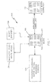
- FIG. 1 illustrates a system 100 utilized to decode or encode information on the magnetic stripes of cards.
- the system comprises a Ticket Handling Module (THM) Micro Controller Board 102 that continually monitors the system for insertion of a magnetic stripe card, such as fare media or credit cards.
- TPM Ticket Handling Module
- the Micro Controller Board 102 sends a signal to transport hardware 104 which captures the card and places the card on a transport belt (not shown).
- transport hardware 104 located in the transport hardware 104, energizes motors which in turn activates the transport belt causing the belt to rotate.
- the rotating transport belt passes the card under magnetic read/write heads 106 at a constant velocity for decoding (reading) and encoding (writing) information on the magnetic stripe of the card.
- Solenoids are utilized to encode data onto the magnetic stripe by methods well known in the art.
- Sensors are utilized to detect when the card is in the proper location within the system for encoding and decoding of data.
- a "swipe" machine can be utilized instead of an "insertion" machine as the card reader.
- the magnetic stripe of the card is used to store information or data.
- Data can include account information, such as a credit card number and expiration date and information relating to transit fares.
- the magnetic stripe is comprised of cells and the data encoded on the card is stored in the cells by way of flux transitions. Each of the cells is the same length and the length of the cell is determined by the bit density of the card. The bit density is a measure of how close together the flux transitions are.
- Typical magnetic stripe cards use F2F encoding to encode the data. In F2F encoding, cells are marked by a beginning and an end, or boundaries. If a flux transition occurs within the boundaries of a cell, then the value of the cell is considered to be a "1".
- the system 100 uses the 3/4 cell time to determine if a flux transition is present within the cell.
- 3/4 cell time is 3/4 of the length of the cell, therefore if the flux transition occurs up to and including 3/4 the length of the cell (3/4 cell time), then the cell is counted as a "1".
- 3/4 is the industry standard for monitoring for a flux transition, however this can be changed to any length including, but not limited, to 7/8, 51% and 63% the length of the cell.
- 3/4 cell time is 3/4 the length of a cell, this time can vary depending on the bit density of the card.
- the system of the present invention can accept cards with various bit densities and encoding formats. For cards of unknown bit densities, the system must determine what the 3/4 cell time is before data can be decoded from the card. Without knowing the 3/4 cell time, the system cannot determine if a flux transition has occurred within the cell boundaries.
- the system To encode/decode data of a card with an unknown bit density, the system must first determine the velocity of the transport belt, or the capstan speed. To determine the velocity, a shaft encoder 108 is utilized. The shaft encoder 108 counts the number of rotations of the belt per a unit time. Based upon the number of rotations of the belt in a given amount of time, the speed of the belt is calculated and the information is transmitted to the Micro Controller Board 102.
- leading zeros which are contained on magnetic stripe cards to compute the 3/4 cell time.
- the leading zeros are a marker on the front of the ticket that indicate a known distance. Based upon the leading zeros, the system knows what a "zero" cell looks like and as a result, knows what a "one" cell looks like. Leading zeros are only needed if the density of the card is not recognized by the system
- the cell times on the leading edge of the card will be measured and this data will be used to calculate the 3/4 cell time by calculating the average cell time of the leading zeros and then taking 3/4 of that time. As the media passes over the read head, the cell times are measured.
- An internal timer on the THM Micro Controller Board 102 is used to measure the time interval between the flux reversals (cell time), thus the cell time is measured.
- the information is transmitted, on the fly, to a Single Board Computer (SBC) or demodulator 110, over a high speed communication link, in the form of a message that consists of a preamble, body and a post amble.
- the preamble contains the belt velocity information and is transmitted when the velocity measurement is complete.
- the body of the message contains the distance from the leading edge of the media to the first flux reversal and the time interval between flux reversals (cell time). This information is transmitted, on the fly, as the flux reversals are detected.
- the post amble is an accumulated CRC that allows the demodulator 110 to authenticate the message.
- the demodulator 110 determines if it has the ability to demodulate and decode the data on the magnetic stripe based upon the bit density of the card. Furthermore, the data can also be used for analysis.
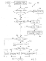
- FIG. 2 is a flow diagram 200 illustrating the process utilized by the demodulator to determine if it can demodulate and decode the data.
- the Micro Controller 102 transmits a data packet, containing the cell time data read from the card by the magnetic read/write heads 104, to the demodulator 110 in the form of serial data 202.
- the data packet consists of a preamble, body and post amble.
- the preamble contains the transport belt velocity and is transmitted when the velocity measurement is complete and is utilized when the card is of an unknown bit density.
- the body of the data packet contains the distance from the leading edge of the media to the first flux reversal and the time interval between flux reversals (cell time).
- the cell time is used to establish the 3/4 cell time to determine if a flux reversal or transition has occurred.
- the postamble is an accumulated Cyclic Redundancy Check (CRC) that allows the demodulator 110 to authenticate the data packet by detecting data transmission errors.
- CRC Cyclic Redundancy Check
- the cell time data (which indicates the bit density of the card) contained in the body of the message is read by the demodulator. If the demodulator supports the bit density of the card, the cell time data is sent to the appropriate demodulator object 204, 206 which receives the cell time data and converts the data to a data stream representing the data that was encoded on the magnetic stripe of the card. This is accomplished by determining if a flux transition has occurred within the 3/4 cell time.
- the appropriate demodulator object is determined by the bit density of the card. Each demodulator object supports a specific density supported by the demodulator.
- Figure 2 illustrates two demodulator objects, a low density demodulator object 204 and a high density demodulator object 206.
- the demodulator object converts binary encoded data on the card to a string of ASCII characters. A binary one is represented as an ASCII one and a binary zero is represented as an ASCII zero. Cell times that do not meet the criteria of a one or a zero are represented as an ASCII zero. This output is suitable for display or further processing.
- bit density is not supported by the demodulator, i.e. the demodulator does not contain a demodulator object that supports the bit density of the card and can convert the data from the card
- a new demodulator object to accept the data of the unknown bit density can be instantiated.
- the system utilizes the leading zeros encoded on the magnetic stripe cards to determine the 3/4 cell time. Based on this information, the bit density of the card can be determined using the velocity of the transport belt contained in the preamble of the data packet and the time between flux transitions. The bit density is equal to the inverse of the transport speed multiplied by the average cell time. A demodulator object can then be instantiated to accommodate the new bit density.
- demodulator objects can also be instantiated for known bit densities.
- the velocity information in the message preamble and the known bit density are used to compute the expected cell timing parameters. Based upon this information, a new demodulator object can be instantiated.
- the demodulator object converts the flux transition time intervals by computing the cell boundary interval and monitoring for a flux change within the cell boundary. As described previously, the absence of a flux change within the boundary is defined as a zero and the presence of a flux change within the cell boundary is defined as a one.
- the demodulator object sends this data stream to a decoder object or media type.
- Figure 2 illustrates five different media types 208, 210, 212, 214, 216.
- Media types are credit cards and various types of fare media cards. Although a system supporting five different media types is shown, one skilled in the art will recognize that any number of media types can be supported.
- the decoder object receives the data stream from the demodulator object and the object decodes and unpacks the data stream. Data bits other than 1 or 0 are ignored.
- the data stream is sent to the ticket validator 218.
- the ticket validator determines the validity of the card presented using the CRC contained in the post amble of the data packet. If the data stream decoded and unpacked from the card is valid, this information is sent to a packer object 220.
- the packer object 220 packs the data into a magnetic stripe format and sends the data to the Micro Controller 102.
- the Micro Controller 102 then can modify the data, such as deduct the appropriate fare from the card if the card is being utilized for a transit system, and encode the data on the card.
- the Micro Controller 102 can encode data onto the magnetic stripe of the card at standard densities using shaft encoder timing or at programmable densities using the internal timers of the Micro Controller 102.
- the shaft encoder 108 encodes data onto the card at a specific density. If the density required is not supported by the shaft encoder 108, internal timers of the Micro Controller 104 can be used to simulate a shaft encoder to encode the proper bit density.
- Figure 3 is a flow diagram illustrating the demodulator process utilized by the demodulator objects 204, 206 of figure 1 to convert the intervals between the flux transitions to a stream of ASCII data that represents the data encoded on the magnetic stripe of the card.
- the demodulator object converts the flux transition time intervals by computing the cell boundary interval and monitoring for a flux change within the cell boundary. The absence of a flux change within the boundary is defined as a zero. The presence of a flux change within the cell boundary is defined as a one.
- a data packet is sent 302 to the demodulator object causing a resume flag to be set to true and an overflow flag to be set to false 304.
- These flags are utilized to determine the cell boundary interval (cell time) and when a flux reversal or transition has occurred.
- the resume flag indicates the end of the cell or the cell boundary. Once the cell boundary has been reached, the resume flag is set to false.
- the overflow flag indicates that a flux transition has not yet occurred and the counter is still counting to determine the cell boundary interval or cell time and the system continues to check for the cell boundary.
- the demodulator object first checks to see if the received cell time is greater than or equal to the 3/4 cell time 306. If the answer is "yes" the overflow flag is changed to true 308 because the demodulator only checks the length of the cell to the 3/4 cell time to determine if a flux transition has occurred. When the cell time is the 3/4 cell time, the system knows if there is a flux transition in the cell and the counter can stop counting, thus the overflow is set to true and the demodulator object checks to see if the cell boundary has been reached 310. If the received cell time is not greater than or equal to the 3/4 cell time, the demodulator object maintains the overflow flag at false and checks if a cell boundary has been reached 310.
- a newbit flag is changed to "not overflow" 312 indicating that the bit that was just decoded is the complement of the overflow flag.
- the newbit flag represents the demodulated bit and is a holder so the bit may be passed on to the decoder object when the entire bit cell has been processed.
- the demodulator checks to see if the newbit flag is set to true 314, in other words, the demodulator object is confirming that a cell boundary has been reached (i.e. a cell boundary flag is set to false). If the newbit flag is false (zero), then the end of the bit cell has been reached.
- the cell boundary flag is set to false and the resume bit is set to false and the demodulator object waits for the next flux transition which will mark the end of the bit cell.
- the demodulator is checking to ascertain if the resume bit is "true”, the demodulator is waiting until the next flux transition. If the answer is "no”, the demodulator object checks to see if the resume bit is true 316.
- the demodulator object checks to see if the new bit flag is "true” 322. If the new bit is not “true”, the decoded data is "0" and there is no flux transition 324. If the new bit is true, the decoded data is "1" and there is a flux transition 326. This demodulated data is then sent to a decoder object. This process continues until all the cells have been checked.
Landscapes
- Engineering & Computer Science (AREA)
- Signal Processing (AREA)
- Artificial Intelligence (AREA)
- Computer Vision & Pattern Recognition (AREA)
- Physics & Mathematics (AREA)
- General Physics & Mathematics (AREA)
- Theoretical Computer Science (AREA)
- Signal Processing For Digital Recording And Reproducing (AREA)
- Devices For Checking Fares Or Tickets At Control Points (AREA)
- Control Of Vending Devices And Auxiliary Devices For Vending Devices (AREA)
- Soft Magnetic Materials (AREA)
Claims (25)
- Procédé permettant la lecture de données stockées sur une bande magnétique d'une carte formant support, d'une densité d'enregistrement en bits inconnue, le procédé comprenant les étapes consistant à :- déterminer la densité d'enregistrement en bits de la carte en mesurant la longueur des cellules situées sur la bande magnétique de la carte en lisant les données à partir de la carte ;- transmettre la densité d'enregistrement en bits et les données contenues dans les cellules vers un démodulateur au moyen d'un paquet de données, le démodulateur comprenant au moins un objet démodulateur et au moins un objet décodeur ;- déterminer si la densité d'enregistrement en bits est prise en charge par le démodulateur en déterminant si le au moins un objet démodulateur reconnaît la densité d'enregistrement en bits de la carte et peut démoduler les données contenues sur la carte ; et enfin- transmettre les données vers l'objet démodulateur pour la démodulation des données si le au moins un objet démodulateur reconnaît la densité d'enregistrement en bits de la carte.
- Procédé selon la revendication 1, comprenant en outre l'étape consistant à instancier un autre objet démodulateur qui prend en charge la densité d'enregistrement en bits de la carte si le au moins un objet démodulateur ne reconnaît pas la densité d'enregistrement en bits de la carte.
- Procédé selon la revendication 1 ou la revendication 2, dans lequel les données démodulées sont une chaîne de caractères ASCII.
- Procédé selon l'une quelconque des revendications 1 à 3, dans lequel les données codées sur la carte sont représentées par une transition de flux.
- Procédé selon la revendication 3 ou 4, comprenant en outre l'étape consistant à transmettre les données démodulées vers le au moins un objet décodeur pour décoder et dégrouper lesdites données démodulées, dans le cas où le au moins un objet décodeur reconnaît le type de carte.
- Procédé selon l'une quelconque des revendications 3 à 5, comprenant en outre l'étape consistant à instancier un autre objet décodeur qui reconnaît le type de carte.
- Procédé selon l'une quelconque des revendications précédentes, comprenant en outre l'étape consistant à mesurer la vitesse d'une courroie de transport d'un lecteur de carte dans lequel le lecteur de carte capture la carte, place la carte sur la courroie de transport et fait passer la carte sous une tête de lecture.
- Procédé selon la revendication 7, dans lequel la vitesse de la courroie de transport est mesurée à l'aide d'un codeur d'arbre au moyen du comptage du nombre de rotations de la courroie pour une unité de temps.
- Procédé selon l'une quelconque des revendications précédentes, dans lequel la longueur des cellules est mesurée au moyen d'un compteur interne du lecteur de carte.
- Procédé selon la revendication 8 ou 9, dans lequel la vitesse est transmise au démodulateur dans un préambule du paquet de données.
- Procédé selon l'une quelconque des revendications 4 à 10, comprenant en outre l'étape consistant à ce que le au moins un objet démodulateur contrôle la cellule pour vérifier la transition de flux.
- Procédé selon l'une quelconque des revendications 4 à 11, comprenant en outre l'étape consistant à déterminer un 3/4 du temps de cellule des cellules sur la bande magnétique, dans le cas où la carte présente une densité inconnue d'enregistrement en bits, au moyen du mesurage des temps de cellule des zéros de tête codés sur la carte, du calcul d'un temps de cellule moyen et de la prise en compte d'un 3/4 du temps moyen de cellule.
- Procédé selon la revendication 12, comprenant en outre les étapes consistant à :- calculer la densité inconnue d'enregistrement en bits en considérant une valeur inverse de la vitesse de la courroie multipliée par le temps moyen de cellule; et enfin- instancier un autre objet démodulateur qui prenne en charge la densité d'enregistrement en bits de la carte.
- Procédé selon l'une quelconque des revendications précédentes, dans lequel la carte est une carte de crédit.
- Procédé selon l'une quelconque des revendications 1 à 13, dans lequel la carte est une carte de transport.
- Appareil (100) permettant la lecture de données stockées sur une bande magnétique d'une carte servant de support (208, 210, 212, 214, 216) présentant une densité d'enregistrement en bits inconnue, l'appareil comprenant :- un lecteur de carte pour lire la densité d'enregistrement en bits inconnue et les données codées sur la bande magnétique de la carte; et- un démodulateur (110) connecté au lecteur de carte par une liaison de communication, le démodulateur comprenant :- au moins un objet démodulateur (204, 206) pour démoduler les données lues à partir de la carte dans le cas où le au moins un objet démodulateur (204, 206) reconnaît la densité d'enregistrement en bits de la carte; et- au moins un objet décodeur, couplé à l'au moins un objet démodulateur (204, 206), pour décoder et dégrouper les données démodulées, dans le cas où le au moins un objet décodeur reconnaît le type de carte.
- Appareil selon la revendication 16, dans lequel les données transmises à partir du lecteur de carte vers le démodulateur au moyen d'un paquet de données qui contient la vitesse d'une courroie de transport utilisée pour le transport de la carte dans le lecteur de carte ainsi que les données lues à partir de la carte.
- Appareil selon la revendication 17, dans lequel les données sont stockées sur la carte dans des cellules et les données sont représentées par des transitions de flux.
- Appareil selon la revendication 16 ou 17, dans lequel la densité d'enregistrement en bits de la carte est calculée dans le cas où la densité d'enregistrement en bits n'est pas reconnue par le au moins un objet démodulateur.
- Appareil selon la revendication 19, dans lequel un 3/4 de temps de cellule des cellules sur la bande magnétique est calculé au moyen du mesurage des temps de cellule des zéros de tête codés sur la carte et par la prise en compte d'une moyenne des temps de cellule mesurés.
- Appareil selon la revendication 20, dans lequel, dans le cas où la densité d'enregistrement en bits n'est pas reconnue par le au moins un objet démodulateur, la densité d'enregistrement en bits est calculée en considérant une valeur inverse de la vitesse de la courroie multipliée par le temps moyen de cellule.
- Appareil selon l'une quelconque des revendications 16 à 21, dans lequel un autre objet démodulateur est instancié dans le cas où le au moins un objet démodulateur ne reconnaît pas la densité d'enregistrement en bits de la carte.
- Appareil selon l'une quelconque des revendications 16 à 22, dans lequel un autre objet décodeur est instancié dans le cas où le au moins un objet décodeur ne reconnaît pas la densité d'enregistrement en bits de la carte.
- Appareil selon l'une quelconque des revendications 16 à 22, dans lequel la carte est une carte de crédit.
- Appareil selon l'une quelconque des revendications 16 à 22, dans lequel la carte est une carte de transport.
Applications Claiming Priority (5)
| Application Number | Priority Date | Filing Date | Title |
|---|---|---|---|
| US31399601P | 2001-08-22 | 2001-08-22 | |
| US313996P | 2001-08-22 | ||
| US10/225,547 US6789736B2 (en) | 2001-08-22 | 2002-08-21 | Distributed architecture for magnetic fare card processing |
| US225547 | 2002-08-21 | ||
| PCT/US2002/026793 WO2003019460A2 (fr) | 2001-08-22 | 2002-08-22 | Architecture repartie pour traitement de carte de transport magnetique |
Publications (2)
| Publication Number | Publication Date |
|---|---|
| EP1433115A2 EP1433115A2 (fr) | 2004-06-30 |
| EP1433115B1 true EP1433115B1 (fr) | 2006-08-16 |
Family
ID=26919693
Family Applications (1)
| Application Number | Title | Priority Date | Filing Date |
|---|---|---|---|
| EP02796414A Expired - Lifetime EP1433115B1 (fr) | 2001-08-22 | 2002-08-22 | Architecture repartie pour traitement de carte de transport magnetique |
Country Status (7)
| Country | Link |
|---|---|
| US (1) | US6789736B2 (fr) |
| EP (1) | EP1433115B1 (fr) |
| AT (1) | ATE336749T1 (fr) |
| AU (1) | AU2002332631B2 (fr) |
| CA (1) | CA2458642C (fr) |
| DE (1) | DE60214021T2 (fr) |
| WO (1) | WO2003019460A2 (fr) |
Families Citing this family (2)
| Publication number | Priority date | Publication date | Assignee | Title |
|---|---|---|---|---|
| WO2004102486A1 (fr) * | 2003-05-13 | 2004-11-25 | Matsushita Electric Industrial Co., Ltd. | Systeme, procede et programme de maintien de valeur, et systeme de transactions |
| US8727219B1 (en) | 2009-10-12 | 2014-05-20 | Dynamics Inc. | Magnetic stripe track signal having multiple communications channels |
Family Cites Families (24)
| Publication number | Priority date | Publication date | Assignee | Title |
|---|---|---|---|---|
| US4047229A (en) | 1975-11-18 | 1977-09-06 | Burroughs Corporation | Velocity controlled manual movement credit card reader |
| JPS5317797A (en) | 1976-07-31 | 1978-02-18 | Japanese National Railways<Jnr> | Card reader |
| US4141044A (en) | 1976-09-17 | 1979-02-20 | The Mosler Safe Company | Magnetically encoded card read/write/capture apparatus |
| US4173026A (en) | 1978-02-23 | 1979-10-30 | Cubic Western Data | Self clocking speed tolerant magnetic recording method and apparatus |
| DE3221445C2 (de) | 1982-01-05 | 1985-03-14 | Dicom Electronics GmbH, 5000 Köln | Kartenlesegerät |
| JPS59195380A (ja) | 1983-04-20 | 1984-11-06 | Hitachi Ltd | ハンド磁気リ−ダライタ |
| GB2165383B (en) | 1984-10-03 | 1988-05-25 | Ncr Co | Data sensing system for currency cassettes |
| US4977502A (en) | 1985-06-28 | 1990-12-11 | Baker Joseph R | Transit vehicle farebox for conducting multi-media transit fare transactions |
| US4788420A (en) | 1985-08-28 | 1988-11-29 | Verifone, Inc. | System and method for reading data record stripes on data cards |
| US5019696A (en) | 1987-08-10 | 1991-05-28 | Verifone, Inc. | System and method for reading data record stripes on data cards |
| JPS63126080A (ja) | 1986-11-14 | 1988-05-30 | Fujitsu Ltd | 記録媒体読取装置 |
| US5298726A (en) | 1988-11-21 | 1994-03-29 | Cubic Automatic Revenue Collection Group | Fare card read-writer which overwrites oldest or invalid data |
| US5168275A (en) | 1990-02-07 | 1992-12-01 | International Business Machines Corporation | Method and apparatus for decoding two frequency (f/2f) data signals |
| US5089694A (en) | 1990-03-07 | 1992-02-18 | General Signal Corporation | Card reader device having automatic means for clamping the card to be read and for automatically ejecting the card at the end of the card reading and writing operations |
| MY106779A (en) * | 1990-09-07 | 1995-07-31 | Mitsubishi Heavy Ind Ltd | Magnetic recording method and circuit for toll road ticket. |
| US5225666A (en) | 1991-05-09 | 1993-07-06 | Verifone, Inc. | Rotary apparatus for data card scanning |
| US5254843A (en) | 1991-08-07 | 1993-10-19 | Hynes John E | Securing magnetically encoded data using timing variations in encoded data |
| DE69222412T2 (de) | 1992-04-15 | 1998-03-26 | International Business Machines Corp., Armonk, N.Y. | Verfahren und Gerät zur Dekodierung von von einem magnetischen Datenträger gelesene F2F-Signalen |
| JPH06274703A (ja) | 1993-01-25 | 1994-09-30 | Omron Corp | カード処理装置 |
| US5367581A (en) | 1993-03-31 | 1994-11-22 | Direct Data Systems | Magnetic reader with read head biased against document by resilient deflection of circuit board |
| US5559317A (en) | 1995-03-27 | 1996-09-24 | International Verifact Inc. | Card reader with carriage powered by movement of inserted card |
| US6053415A (en) | 1998-02-02 | 2000-04-25 | Norwood; Mark | Apparatus and method for manually encoding a magnetic stripe |
| US6049478A (en) | 1999-03-04 | 2000-04-11 | Hewlett Packard Company | Digital magnetic read channel and method |
| US20020158122A1 (en) | 2001-04-30 | 2002-10-31 | Fisher David Landis | Method and system to interpret and manage different smart card data architectures |
-
2002
- 2002-08-21 US US10/225,547 patent/US6789736B2/en not_active Expired - Fee Related
- 2002-08-22 AT AT02796414T patent/ATE336749T1/de not_active IP Right Cessation
- 2002-08-22 DE DE60214021T patent/DE60214021T2/de not_active Expired - Fee Related
- 2002-08-22 CA CA2458642A patent/CA2458642C/fr not_active Expired - Fee Related
- 2002-08-22 EP EP02796414A patent/EP1433115B1/fr not_active Expired - Lifetime
- 2002-08-22 WO PCT/US2002/026793 patent/WO2003019460A2/fr not_active Ceased
- 2002-08-22 AU AU2002332631A patent/AU2002332631B2/en not_active Ceased
Also Published As
| Publication number | Publication date |
|---|---|
| US6789736B2 (en) | 2004-09-14 |
| WO2003019460A2 (fr) | 2003-03-06 |
| CA2458642C (fr) | 2011-05-24 |
| WO2003019460A3 (fr) | 2003-09-25 |
| ATE336749T1 (de) | 2006-09-15 |
| DE60214021T2 (de) | 2007-03-01 |
| DE60214021D1 (de) | 2006-09-28 |
| US20030042307A1 (en) | 2003-03-06 |
| AU2002332631B2 (en) | 2006-07-27 |
| EP1433115A2 (fr) | 2004-06-30 |
| CA2458642A1 (fr) | 2003-03-06 |
| HK1067753A1 (en) | 2005-04-15 |
Similar Documents
| Publication | Publication Date | Title |
|---|---|---|
| KR970011124B1 (ko) | 유료도로통행권의 자기기록변환방법 및 자기카드의 디지틀기록·재생회로 | |
| US4507550A (en) | High security credit card, system and method | |
| CN103793674A (zh) | 读卡器及读卡器的控制方法 | |
| EP1433115B1 (fr) | Architecture repartie pour traitement de carte de transport magnetique | |
| CA2228615A1 (fr) | Carte de credit sure | |
| US4246474A (en) | Method and apparatus for reading magnetically coded data | |
| EP0789314A2 (fr) | Décodeur de capteur double | |
| AU2002332631A1 (en) | Distributed architecture for magnetic fare card processing | |
| HK1067753B (en) | Distributed architecture for magnetic fare card processing | |
| US4880963A (en) | Encoding magnetic cards | |
| US5028768A (en) | System for reading and encoding a magnetic track carried by a manually-displaced supporting document | |
| JPH0678037B2 (ja) | 認証識別媒体の認証装置 | |
| JPH0438045B2 (fr) | ||
| US3619570A (en) | Magnetic reading apparatus | |
| EP0024800A1 (fr) | Document et système de sécurité | |
| WO1998008196A1 (fr) | Lecteur magnetique | |
| EP1256094B1 (fr) | Ticket dote d'une couche magnetique, et appareil d'emission, de validation et d'inspection de tels tickets | |
| US11468250B2 (en) | Reader device for reading information stored on a magnetic strip and a method for decoding the read information | |
| JP3042265B2 (ja) | 磁気カード及び磁気カード判定装置 | |
| JPH0737027A (ja) | 磁性コード印刷物、その読取り方法および装置 | |
| JP2550634B2 (ja) | 磁気カードリーダ | |
| US4338513A (en) | Bistable magnetic wire badge reader | |
| GB2186732A (en) | Improvements in encoding magnetic cards | |
| JPS60575A (ja) | 磁気インク文字読取装置 | |
| JPH01213786A (ja) | プリペイドカードの搬送制御方式 |
Legal Events
| Date | Code | Title | Description |
|---|---|---|---|
| PUAI | Public reference made under article 153(3) epc to a published international application that has entered the european phase |
Free format text: ORIGINAL CODE: 0009012 |
|
| 17P | Request for examination filed |
Effective date: 20040322 |
|
| AK | Designated contracting states |
Kind code of ref document: A2 Designated state(s): AT BE BG CH CY CZ DE DK EE ES FI FR GB GR IE IT LI LU MC NL PT SE SK TR |
|
| AX | Request for extension of the european patent |
Extension state: AL LT LV MK RO SI |
|
| 17Q | First examination report despatched |
Effective date: 20040702 |
|
| REG | Reference to a national code |
Ref country code: HK Ref legal event code: DE Ref document number: 1067753 Country of ref document: HK |
|
| GRAP | Despatch of communication of intention to grant a patent |
Free format text: ORIGINAL CODE: EPIDOSNIGR1 |
|
| GRAS | Grant fee paid |
Free format text: ORIGINAL CODE: EPIDOSNIGR3 |
|
| GRAA | (expected) grant |
Free format text: ORIGINAL CODE: 0009210 |
|
| AK | Designated contracting states |
Kind code of ref document: B1 Designated state(s): AT BE BG CH CY CZ DE DK EE ES FI FR GB GR IE IT LI LU MC NL PT SE SK TR |
|
| PG25 | Lapsed in a contracting state [announced via postgrant information from national office to epo] |
Ref country code: LI Free format text: LAPSE BECAUSE OF FAILURE TO SUBMIT A TRANSLATION OF THE DESCRIPTION OR TO PAY THE FEE WITHIN THE PRESCRIBED TIME-LIMIT Effective date: 20060816 Ref country code: FI Free format text: LAPSE BECAUSE OF FAILURE TO SUBMIT A TRANSLATION OF THE DESCRIPTION OR TO PAY THE FEE WITHIN THE PRESCRIBED TIME-LIMIT Effective date: 20060816 Ref country code: CH Free format text: LAPSE BECAUSE OF FAILURE TO SUBMIT A TRANSLATION OF THE DESCRIPTION OR TO PAY THE FEE WITHIN THE PRESCRIBED TIME-LIMIT Effective date: 20060816 Ref country code: NL Free format text: LAPSE BECAUSE OF FAILURE TO SUBMIT A TRANSLATION OF THE DESCRIPTION OR TO PAY THE FEE WITHIN THE PRESCRIBED TIME-LIMIT Effective date: 20060816 Ref country code: CZ Free format text: LAPSE BECAUSE OF FAILURE TO SUBMIT A TRANSLATION OF THE DESCRIPTION OR TO PAY THE FEE WITHIN THE PRESCRIBED TIME-LIMIT Effective date: 20060816 Ref country code: BE Free format text: LAPSE BECAUSE OF FAILURE TO SUBMIT A TRANSLATION OF THE DESCRIPTION OR TO PAY THE FEE WITHIN THE PRESCRIBED TIME-LIMIT Effective date: 20060816 Ref country code: SK Free format text: LAPSE BECAUSE OF FAILURE TO SUBMIT A TRANSLATION OF THE DESCRIPTION OR TO PAY THE FEE WITHIN THE PRESCRIBED TIME-LIMIT Effective date: 20060816 Ref country code: AT Free format text: LAPSE BECAUSE OF FAILURE TO SUBMIT A TRANSLATION OF THE DESCRIPTION OR TO PAY THE FEE WITHIN THE PRESCRIBED TIME-LIMIT Effective date: 20060816 Ref country code: IT Free format text: LAPSE BECAUSE OF FAILURE TO SUBMIT A TRANSLATION OF THE DESCRIPTION OR TO PAY THE FEE WITHIN THE PRESCRIBED TIME-LIMIT;WARNING: LAPSES OF ITALIAN PATENTS WITH EFFECTIVE DATE BEFORE 2007 MAY HAVE OCCURRED AT ANY TIME BEFORE 2007. THE CORRECT EFFECTIVE DATE MAY BE DIFFERENT FROM THE ONE RECORDED. Effective date: 20060816 |
|
| REG | Reference to a national code |
Ref country code: GB Ref legal event code: FG4D |
|
| PG25 | Lapsed in a contracting state [announced via postgrant information from national office to epo] |
Ref country code: IE Free format text: LAPSE BECAUSE OF NON-PAYMENT OF DUE FEES Effective date: 20060822 |
|
| PG25 | Lapsed in a contracting state [announced via postgrant information from national office to epo] |
Ref country code: MC Free format text: LAPSE BECAUSE OF NON-PAYMENT OF DUE FEES Effective date: 20060831 |
|
| REG | Reference to a national code |
Ref country code: CH Ref legal event code: EP |
|
| REG | Reference to a national code |
Ref country code: IE Ref legal event code: FG4D |
|
| REF | Corresponds to: |
Ref document number: 60214021 Country of ref document: DE Date of ref document: 20060928 Kind code of ref document: P |
|
| PG25 | Lapsed in a contracting state [announced via postgrant information from national office to epo] |
Ref country code: DK Free format text: LAPSE BECAUSE OF FAILURE TO SUBMIT A TRANSLATION OF THE DESCRIPTION OR TO PAY THE FEE WITHIN THE PRESCRIBED TIME-LIMIT Effective date: 20061116 Ref country code: SE Free format text: LAPSE BECAUSE OF FAILURE TO SUBMIT A TRANSLATION OF THE DESCRIPTION OR TO PAY THE FEE WITHIN THE PRESCRIBED TIME-LIMIT Effective date: 20061116 Ref country code: BG Free format text: LAPSE BECAUSE OF FAILURE TO SUBMIT A TRANSLATION OF THE DESCRIPTION OR TO PAY THE FEE WITHIN THE PRESCRIBED TIME-LIMIT Effective date: 20061116 |
|
| PG25 | Lapsed in a contracting state [announced via postgrant information from national office to epo] |
Ref country code: ES Free format text: LAPSE BECAUSE OF FAILURE TO SUBMIT A TRANSLATION OF THE DESCRIPTION OR TO PAY THE FEE WITHIN THE PRESCRIBED TIME-LIMIT Effective date: 20061127 |
|
| PG25 | Lapsed in a contracting state [announced via postgrant information from national office to epo] |
Ref country code: PT Free format text: LAPSE BECAUSE OF FAILURE TO SUBMIT A TRANSLATION OF THE DESCRIPTION OR TO PAY THE FEE WITHIN THE PRESCRIBED TIME-LIMIT Effective date: 20070116 |
|
| NLV1 | Nl: lapsed or annulled due to failure to fulfill the requirements of art. 29p and 29m of the patents act | ||
| REG | Reference to a national code |
Ref country code: CH Ref legal event code: PL |
|
| REG | Reference to a national code |
Ref country code: HK Ref legal event code: GR Ref document number: 1067753 Country of ref document: HK |
|
| EN | Fr: translation not filed | ||
| PLBE | No opposition filed within time limit |
Free format text: ORIGINAL CODE: 0009261 |
|
| STAA | Information on the status of an ep patent application or granted ep patent |
Free format text: STATUS: NO OPPOSITION FILED WITHIN TIME LIMIT |
|
| 26N | No opposition filed |
Effective date: 20070518 |
|
| PGFP | Annual fee paid to national office [announced via postgrant information from national office to epo] |
Ref country code: DE Payment date: 20071001 Year of fee payment: 6 |
|
| PG25 | Lapsed in a contracting state [announced via postgrant information from national office to epo] |
Ref country code: GR Free format text: LAPSE BECAUSE OF FAILURE TO SUBMIT A TRANSLATION OF THE DESCRIPTION OR TO PAY THE FEE WITHIN THE PRESCRIBED TIME-LIMIT Effective date: 20061117 Ref country code: FR Free format text: LAPSE BECAUSE OF FAILURE TO SUBMIT A TRANSLATION OF THE DESCRIPTION OR TO PAY THE FEE WITHIN THE PRESCRIBED TIME-LIMIT Effective date: 20070511 |
|
| PG25 | Lapsed in a contracting state [announced via postgrant information from national office to epo] |
Ref country code: EE Free format text: LAPSE BECAUSE OF FAILURE TO SUBMIT A TRANSLATION OF THE DESCRIPTION OR TO PAY THE FEE WITHIN THE PRESCRIBED TIME-LIMIT Effective date: 20060816 |
|
| PG25 | Lapsed in a contracting state [announced via postgrant information from national office to epo] |
Ref country code: LU Free format text: LAPSE BECAUSE OF NON-PAYMENT OF DUE FEES Effective date: 20060822 Ref country code: TR Free format text: LAPSE BECAUSE OF FAILURE TO SUBMIT A TRANSLATION OF THE DESCRIPTION OR TO PAY THE FEE WITHIN THE PRESCRIBED TIME-LIMIT Effective date: 20060816 |
|
| PG25 | Lapsed in a contracting state [announced via postgrant information from national office to epo] |
Ref country code: FR Free format text: LAPSE BECAUSE OF FAILURE TO SUBMIT A TRANSLATION OF THE DESCRIPTION OR TO PAY THE FEE WITHIN THE PRESCRIBED TIME-LIMIT Effective date: 20060816 Ref country code: CY Free format text: LAPSE BECAUSE OF FAILURE TO SUBMIT A TRANSLATION OF THE DESCRIPTION OR TO PAY THE FEE WITHIN THE PRESCRIBED TIME-LIMIT Effective date: 20060816 |
|
| PG25 | Lapsed in a contracting state [announced via postgrant information from national office to epo] |
Ref country code: DE Free format text: LAPSE BECAUSE OF NON-PAYMENT OF DUE FEES Effective date: 20090303 |
|
| PGFP | Annual fee paid to national office [announced via postgrant information from national office to epo] |
Ref country code: GB Payment date: 20130827 Year of fee payment: 12 |
|
| GBPC | Gb: european patent ceased through non-payment of renewal fee |
Effective date: 20140822 |
|
| PG25 | Lapsed in a contracting state [announced via postgrant information from national office to epo] |
Ref country code: GB Free format text: LAPSE BECAUSE OF NON-PAYMENT OF DUE FEES Effective date: 20140822 |