EP1433372A1 - Andaineuse rotative - Google Patents
Andaineuse rotative Download PDFInfo
- Publication number
- EP1433372A1 EP1433372A1 EP03025218A EP03025218A EP1433372A1 EP 1433372 A1 EP1433372 A1 EP 1433372A1 EP 03025218 A EP03025218 A EP 03025218A EP 03025218 A EP03025218 A EP 03025218A EP 1433372 A1 EP1433372 A1 EP 1433372A1
- Authority
- EP
- European Patent Office
- Prior art keywords
- swath
- rotary
- swather
- rotary swather
- rotors
- Prior art date
- Legal status (The legal status is an assumption and is not a legal conclusion. Google has not performed a legal analysis and makes no representation as to the accuracy of the status listed.)
- Granted
Links
- 230000015572 biosynthetic process Effects 0.000 claims description 8
- 238000001514 detection method Methods 0.000 claims description 7
- 230000002706 hydrostatic effect Effects 0.000 claims description 3
- 238000006073 displacement reaction Methods 0.000 claims description 2
- 230000008878 coupling Effects 0.000 description 17
- 238000010168 coupling process Methods 0.000 description 17
- 238000005859 coupling reaction Methods 0.000 description 17
- 239000004459 forage Substances 0.000 description 3
- 230000005540 biological transmission Effects 0.000 description 2
- 230000005611 electricity Effects 0.000 description 2
- 238000003306 harvesting Methods 0.000 description 2
- 241001124569 Lycaenidae Species 0.000 description 1
- 230000006978 adaptation Effects 0.000 description 1
- 230000000903 blocking effect Effects 0.000 description 1
- 238000006243 chemical reaction Methods 0.000 description 1
- 238000005352 clarification Methods 0.000 description 1
- 230000002860 competitive effect Effects 0.000 description 1
- 230000001419 dependent effect Effects 0.000 description 1
- 238000010586 diagram Methods 0.000 description 1
- 238000000034 method Methods 0.000 description 1
- 239000002689 soil Substances 0.000 description 1
Images








Classifications
-
- A—HUMAN NECESSITIES
- A01—AGRICULTURE; FORESTRY; ANIMAL HUSBANDRY; HUNTING; TRAPPING; FISHING
- A01D—HARVESTING; MOWING
- A01D78/00—Haymakers with tines moving with respect to the machine
- A01D78/08—Haymakers with tines moving with respect to the machine with tine-carrying rotary heads or wheels
- A01D78/10—Haymakers with tines moving with respect to the machine with tine-carrying rotary heads or wheels the tines rotating about a substantially vertical axis
- A01D78/1007—Arrangements to facilitate transportation specially adapted therefor
- A01D78/1014—Folding frames
-
- A—HUMAN NECESSITIES
- A01—AGRICULTURE; FORESTRY; ANIMAL HUSBANDRY; HUNTING; TRAPPING; FISHING
- A01D—HARVESTING; MOWING
- A01D78/00—Haymakers with tines moving with respect to the machine
- A01D78/08—Haymakers with tines moving with respect to the machine with tine-carrying rotary heads or wheels
- A01D78/10—Haymakers with tines moving with respect to the machine with tine-carrying rotary heads or wheels the tines rotating about a substantially vertical axis
- A01D78/1007—Arrangements to facilitate transportation specially adapted therefor
-
- A—HUMAN NECESSITIES
- A01—AGRICULTURE; FORESTRY; ANIMAL HUSBANDRY; HUNTING; TRAPPING; FISHING
- A01D—HARVESTING; MOWING
- A01D78/00—Haymakers with tines moving with respect to the machine
- A01D78/08—Haymakers with tines moving with respect to the machine with tine-carrying rotary heads or wheels
- A01D78/10—Haymakers with tines moving with respect to the machine with tine-carrying rotary heads or wheels the tines rotating about a substantially vertical axis
- A01D78/1021—Telescopic frames
-
- A—HUMAN NECESSITIES
- A01—AGRICULTURE; FORESTRY; ANIMAL HUSBANDRY; HUNTING; TRAPPING; FISHING
- A01D—HARVESTING; MOWING
- A01D78/00—Haymakers with tines moving with respect to the machine
- A01D78/08—Haymakers with tines moving with respect to the machine with tine-carrying rotary heads or wheels
- A01D78/10—Haymakers with tines moving with respect to the machine with tine-carrying rotary heads or wheels the tines rotating about a substantially vertical axis
- A01D78/1092—Having more than two rows of rotors on more than two different horizontal lines perpendicular to the advance direction of the machine
Definitions
- the invention relates to a rotary swather according to the preamble of independent claims.
- EP 0 819 372 describes a rotary swather with four swath rotors, the in the CLAAS brochure "Schwader LINER, edition 8/01 (DC) 200/248 522.0 is shown and described. Such a rake with four Swathing is shown under the trade name LINER 3000 and described. The reachable working width of four-rotor swathers Type is currently around 15 meters.
- the object of the invention is to provide a rake with an even wider working width to create from the point of view of great flexibility in terms of Adaptation options to different operating conditions in order to achieve this to ensure the economy in large-scale use, the Rakes should be designed so that, despite its large working width can be guided safely and that this is in a road transport profile can convince, the legal and traffic regulations equivalent.
- the invention sees a rotary swather with staggered arrangement Swaths in such a way that they move forward in a V-shaped arrangement open in the direction of travel in at least three rows in a row are arranged, with at least one row of rows behind a chassis and at least two rows of squadrons are arranged in front of a landing gear, and thereby at least the relay rows in front of the undercarriage via length-adjustable booms feature.
- the brackets have All series of rows via adjustable booms.
- the length-adjustable boom preferably as a telescopic boom designed
- the actuators for retracting or extending preferably in itself are known to be formed by hydraulic cylinders.
- the booms are hinged to a chassis in hinged joints and they can move around the articulated axes pointing in the direction of travel Working position in its transport position in a known manner from Hydraulic cylinders can be folded up as actuators.
- Hydraulic cylinders can be folded up as actuators.
- On the free outside At the end of the boom are the actual swath rotors, which are in their Support the working position against the ground on your own trolleys.
- the swath rotor is articulated in such a way that it is known Way to adapt to the soil profile during their forward movement.
- the rotary swather according to the invention shows working widths that are far above extend that measure of the known. For example, with six Swath rotors reach working widths of up to 22 meters. This demands Booms that have a corresponding distance between the swath rotor and the Bridge machine frame and on the other hand are able to To spend swath rotors in a transport position that is about a width of 3 Meters and about 4 meters in height.
- the swath rotor is preferably driven by a PTO-driven drivetrains made up of different cardan shafts and Assemble branching gears. But also hydraulic drives, formed from hydraulic motors that are directly attached to the swath rotors, are possible.
- switchable bevel gear attached in the direction of the swath extending drive trains from the main drive train through switchable Clutches can be switched on or off and also in their direction of rotation can be switched.
- This enables a particularly flexible Use of a large swather according to the invention. For example solely by varying the rotation direction assignments of the swath rotors different swaths are generated. This allows you to choose either one large swath in the main middle level or three individual swaths spaced apart symmetrically to the main median plane.
- By individual control of the length of each individual boom of the relay series can set the optimal spacing between the swath rotors become.
- This adjustment process can be carried out by the hydraulic actuators the driver's cabin can also be made while driving.
- a large swather according to the invention can also be designed as a self-propelled swather.
- the self-propelled rake can have a power car, which is supported on a steerable front axle and which also has a steerable rear axle.
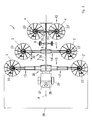
- Fig. 1 shows an embodiment of the invention using the example of a drawn Large swathers as rotary swather 1 with six on the ground via wheels supported swath rotors 2.2 ', 3.3', 4.4 'in a plan view in the working position in unfolded state of the swath rotors 2,2 ', 3,3', 4,4 'and thus in the extended Condition of the boom, 13.13 ', 14.14', 15.15 '.
- the chassis 5 is connected to the tractor 7 in by means of a coupling device 6 connected to the lower links as a pulling device.
- the drawbar The longitudinal beam 35 is in turn in the tension joint 33 about a vertical axis 34 pivotably and freely trailing connected to the coupling device 6.
- the chassis 5 is opposed by a chassis 8 with the wheels 9 supported the ground.
- the wheels 9 are preferably with a Steering device equipped in a conventional manner, the steering angle of the wheels depending on the steering angle between the Coupling device 6 and the tiller-forming side member 35 controls. This improves the caster behavior compared to the directional stability the tractor and increases maneuverability in terms of maneuverability.
- the arms 13, 13 ', 14, 14' of the swath rotors 2.2 ', 3.3' are shown in the figure Example of the invention in front of the chassis 8 of the chassis 5 and the Swath rotor 4,4 'arranged behind the chassis 8. But the chassis can likewise in the area of the longitudinal extension between the first series of seasons and the third season row. This results in a staggered Arrangement of the swath rotors 2,2 '; 3,3'; 4,4 ', which is open in the direction of travel F V-shaped Represents arrangement.
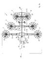
- Fig. 2 shows an embodiment of the invention shown using the example of a self-propelled rotary swather 1 in a plan view in the working position analogous to Fig. 1.
- the rotary swather 1 with a drive head 37, which is supported on a driven front axle 38 with its steerable drive wheels 39 against the ground is connected.
- the drive head 37 can be connected rigidly as well as articulatedly to the chassis 5 of the rotary swather 1.
- Fig. 2 shows an embodiment for a rigid coupling.
- Fig. 2a shows an embodiment for an articulated coupling between the drive head 37 and the drawbar-forming longitudinal beam 35 of the chassis 5.
- the front wheels 39 and The wheels of the rear wheels 9 can be steered independently or independently of one another.
- FIG. 2b shows a driving situation of a rotary swather 1 according to FIG. 2a in one Turning maneuvers in a reverse drive with independently steerable Front axle 38 and rear axle of the chassis 8 in connection with the Articulated steering around the vertical axis 34 of the tension joint 33.
- This configuration is anlog transferable in its application to the team situation between Tractor 7 and rotary swather 1 according to FIG. 1.
- This inventive design of the steerability offers a special dynamic mobility of the rotary swather 1 in a small space in difficult circumstances.
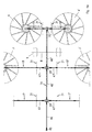
- FIG. 3 shows an exemplary embodiment of a rotary swather 1 according to FIG. 1 but with a different rotation direction assignment of the swath rotors 2.2 ', 3.3', 4.4 ' shown one below the other.
- the directions of rotation 23, 23 'of the swath are 3, 3 'of the series of rows 11 reversed compared to the embodiment according to FIG. opposed. This enables a different form of swath formation and Swath.
- three individual swaths 25 formed and placed at a distance of 40.40 'to each other.
- the total working width 28 can also be varied in the same way, i.e. be adapted to the feed stock or the spatial conditions. This can preferably by the design of the boom 13,13'14,14'15,15 ' telescopic and thus length-adjustable booms are generated.
- the Control elements of the telescope are not for reasons of clarity shown.
- Such actuators can, for example, by hydraulic cylinders be formed with differential pistons.
- these hydraulic cylinders can also be used Displacement transducers can be designed as a length measuring system.
- the current one Actual state i.e. the current position of the piston and thus the current
- the position of the swath can thus be detected and, for example, on a Terminal can be visualized.
- a microprocessor for example in connection with a BUS system (LBS or ISO-BUS) the ease of use and the operational safety are significantly increased, by performing all the positioning operations from the driver's seat at the push of a button can be and at the same time in a particularly simple manner Plausibility checks can be carried out to avoid incorrect operation can prevent. This lowers the risk of accidents and the risk of Damage to the machine equipment.
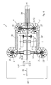
- 4 is an embodiment for driving the rotary swather 1 after presented the invention.
- 4a shows an enlarged detail from FIG better clarification of further details.
- the swath rotors 2,2 ', 3,3', 4,4 ' are themselves generally known angular gear, on its representation and description therefore at this point it can be omitted with the ends of the drive trains 17.17 ', 18.18', 19.19 '.
- the main drive train 16 is connected to the PTO shaft 45 of the tractor 7 or Drive head 37 connected and it runs along the direction of travel F approximately in the Main center plane 36.
- Angular gear 20,21,22 which have outgoing output shafts on which Connect branches 17.17 ', 18.18', 19.19 '.
- the Drive shafts as cardan shaft connections 47, 47 'designed so that they Forms of movement of the swath rotors 2,2 ', 3,3', 4,4 'both in operation and for Obey transfer to the transport position.
- 4b shows an exemplary embodiment for a branching of the drive trains 16, 18, 18 'using the example of the bevel gear 21.
- a gearbox 55 is a bevel gear, consisting of the bevel gears 49, 50, 50 '.
- the through shaft 51 as part of the main drive train 16 is in the Cardan joints 56 connected to the drive shafts 46 ', 46 ".
- One part of the clutch 48 is with the bevel gear 50 and the other part with the Output shaft 52 non-rotatably connected.
- FIG. 4c shows an expanded version of the gearbox analogous to FIG. 4b the possibility of reversing the direction of rotation of the drive trains 18, 18 'and thus the Reversal of the direction of rotation of the swath rotor 3,3 '.
- the bevel gear 3b expanded by a further bevel gear 49 '.
- the rotationally fixed connections between the bevel gears 49 and 49 'with the Drive shaft 51 through switchable clutches 59, 59 ', also as electrically operable multi-plate clutches can be made.
- switchable clutches 59, 59 ' also as electrically operable multi-plate clutches
- Through optional actuation and clutches 59, 59 'in engagement position that is, by the clutch 59 or clutch 59 'engaged
- Direction of rotation of the output strands 18, 18 ' can be reversed.
- the branch lines are 17.17 ', 18.18', 19.19 'preferably by switchable couplings 48.48' Transmission of the drive torques with the angular gear 20,21,22 coupled.
- These couplings 48, 48 ' can, for example, be electrical or hydraulically operated and remotely controlled from the driver's cab, or for example, manually operable engaging and disengaging Be blocking body couplings.
- the invention is essential the possibility of at least one of the branch lines 17, 17 ', 18, 18', 19, 19 ' or in an extended form even all branch strands 17.17 ', 18.18', 19.19 ' to be able to switch on and off independently of each other.
- middle drive trains 18,18 'to make their direction of rotation switchable.
- this can be generated by the fact that the respective Angular gear 21 two on each side of the longitudinal median plane 36 Output shaft journal with different directions of rotation, so that the adjoining cardan shafts can only be repositioned to generate different directions of rotation.
- manual transmissions can be used instead of switchable clutches that allow changing directions of rotation or switchable Generate powertrains.
- the drive system described below can also be used hydrostatic or electric drives, directly or indirectly blocked on the Swath rotors 2.2 ', 3.3', 4.4 '.
- Hydrostatic or electrical directly drive motors blocked on the swath rotors 2,2 ', 3,3', 4,4 ' make it possible particularly simple way the swath rotors in their direction of rotation 23, 23 ' to control, or to switch this off on the drive side.
- Another particularly advantageous embodiment of the invention consists in that, for example, all swath rotors of a left or right half of one Swing up the rotary swather 1 according to the invention and completely on the drive side Disengage so the other half remaining engaged the rotary swather 1 can be used as a pure side swather.
- Such one Application is shown in Fig. 5.
- the total working width is thus halved to a reduced working width 29.
- variable design of the working width 28 ' in particular by the boom 12, 12 ', 13, 13' can be varied in their extended length.
- the working width can also be increased from the working width 28 to a working width 28 ' can be reduced by the front working gyroscopes 2,2 'being completely folded up and be disengaged on the drive side.
- This application is shown in Fig. 7 shown.
- FIG. 8 shows another possible application of the rotary swather 1 of the invention for the formation of wide swaths 58 for inclusion by a wide pick-up as a collection device for subsequent operations.
- a wide pick-up pickup device can be used, for example, as a front attachment Forage harvesters are used.
- the invention thus offers a wide range of variable possible uses of the rotary swather 1 as a large-area swather according to the invention.
- a rotary swather 1 as Medium rake with considerably variable working width 28.28 'and more variable Swath width 41, as a rotary swather 1 with multiple swath placement and variable Swath width 41 in conjunction with variable swath spacing 40.40 'and as pure side swather at the place of the current use without conversion work in Function.
- Rotary rake 1 of this size with a crop edge guide and / or Obstacle detection system 60, 60 'as shown in FIG. 9 is represented symbolically.
- These known systems for example Laser-guided, such a guidance system enables the boundary line between an area that has already been cleared and the area that has not yet been cleared recognize so that the control of the tractor 7 or the self-propelled Rotary swather can be done automatically.
- Obstacle detection systems that can also be integrated in the existing edge guide system Collisions, for example with electricity pylons, trees or fence posts prevent.
- Fig. 10 is a rotary swather 1 according to the invention in the transport position Swath rotors 2,2 ', 3,3', 4,4 'shown completely to the side. To all adjustable booms are folded into their shortest before folding up Position transferred. In addition, for example, an additional The chassis is lowered so that the total height of the Rotary swather 1 can be additionally reduced in the transport journey.
Landscapes
- Life Sciences & Earth Sciences (AREA)
- Environmental Sciences (AREA)
- Harvester Elements (AREA)
- Crystals, And After-Treatments Of Crystals (AREA)
- Polishing Bodies And Polishing Tools (AREA)
- Soil Working Implements (AREA)
- Permanent Magnet Type Synchronous Machine (AREA)
- Iron Core Of Rotating Electric Machines (AREA)
- Induction Machinery (AREA)
- Agricultural Machines (AREA)
- Combined Means For Separation Of Solids (AREA)
- Refuse-Collection Vehicles (AREA)
Priority Applications (4)
| Application Number | Priority Date | Filing Date | Title |
|---|---|---|---|
| DK07002021.9T DK1774846T3 (da) | 2002-12-13 | 2003-11-05 | Rotorrive |
| EP06003554A EP1658768A1 (fr) | 2002-12-13 | 2003-11-05 | Andaineuse rotative |
| EP06003558A EP1676476A1 (fr) | 2002-12-13 | 2003-11-05 | Andaineuse rotative |
| EP07002021A EP1774846B1 (fr) | 2002-12-13 | 2003-11-05 | Andaineuse rotative |
Applications Claiming Priority (2)
| Application Number | Priority Date | Filing Date | Title |
|---|---|---|---|
| DE10258661A DE10258661A1 (de) | 2002-12-13 | 2002-12-13 | Kreiselschwader |
| DE10258661 | 2002-12-13 |
Related Child Applications (3)
| Application Number | Title | Priority Date | Filing Date |
|---|---|---|---|
| EP06003558A Division EP1676476A1 (fr) | 2002-12-13 | 2003-11-05 | Andaineuse rotative |
| EP07002021A Division EP1774846B1 (fr) | 2002-12-13 | 2003-11-05 | Andaineuse rotative |
| EP06003554A Division EP1658768A1 (fr) | 2002-12-13 | 2003-11-05 | Andaineuse rotative |
Publications (2)
| Publication Number | Publication Date |
|---|---|
| EP1433372A1 true EP1433372A1 (fr) | 2004-06-30 |
| EP1433372B1 EP1433372B1 (fr) | 2007-07-18 |
Family
ID=32403820
Family Applications (4)
| Application Number | Title | Priority Date | Filing Date |
|---|---|---|---|
| EP06003554A Ceased EP1658768A1 (fr) | 2002-12-13 | 2003-11-05 | Andaineuse rotative |
| EP06003558A Ceased EP1676476A1 (fr) | 2002-12-13 | 2003-11-05 | Andaineuse rotative |
| EP07002021A Expired - Lifetime EP1774846B1 (fr) | 2002-12-13 | 2003-11-05 | Andaineuse rotative |
| EP03025218A Expired - Lifetime EP1433372B1 (fr) | 2002-12-13 | 2003-11-05 | Andaineuse rotative |
Family Applications Before (3)
| Application Number | Title | Priority Date | Filing Date |
|---|---|---|---|
| EP06003554A Ceased EP1658768A1 (fr) | 2002-12-13 | 2003-11-05 | Andaineuse rotative |
| EP06003558A Ceased EP1676476A1 (fr) | 2002-12-13 | 2003-11-05 | Andaineuse rotative |
| EP07002021A Expired - Lifetime EP1774846B1 (fr) | 2002-12-13 | 2003-11-05 | Andaineuse rotative |
Country Status (4)
| Country | Link |
|---|---|
| EP (4) | EP1658768A1 (fr) |
| AT (1) | ATE367081T1 (fr) |
| DE (2) | DE10258661A1 (fr) |
| DK (1) | DK1774846T3 (fr) |
Cited By (16)
| Publication number | Priority date | Publication date | Assignee | Title |
|---|---|---|---|---|
| EP1488682A1 (fr) * | 2003-06-20 | 2004-12-22 | Maschinenfabrik Bernard Krone GmbH | Machine de fenaison |
| EP1488683A1 (fr) * | 2003-06-20 | 2004-12-22 | Maschinenfabrik Bernard Krone GmbH | Machine de fenaison |
| EP1488679A1 (fr) * | 2003-06-20 | 2004-12-22 | Maschinenfabrik Bernard Krone GmbH | Machine de fenaison |
| EP1488681A1 (fr) * | 2003-06-20 | 2004-12-22 | Maschinenfabrik Bernard Krone GmbH | Machine de fenaison |
| EP1488680A1 (fr) * | 2003-06-20 | 2004-12-22 | Maschinenfabrik Bernard Krone GmbH | Machine de fenaison |
| EP1493320A1 (fr) * | 2003-06-20 | 2005-01-05 | Maschinenfabrik Bernard Krone GmbH | Machine de fenaison |
| EP1493321A1 (fr) * | 2003-06-20 | 2005-01-05 | Maschinenfabrik Bernard Krone GmbH | Machine de fenaison |
| EP1527673A1 (fr) * | 2003-10-31 | 2005-05-04 | Claas Saulgau Gmbh | Andaineuse rotative |
| EP1665922A1 (fr) * | 2004-12-03 | 2006-06-07 | Maschinenfabrik Bernard Krone GmbH | Machine de fenaison |
| EP1716742A1 (fr) * | 2005-04-27 | 2006-11-02 | Claas Saulgau Gmbh | Appareil pour la récolte |
| EP1935229A1 (fr) * | 2006-12-20 | 2008-06-25 | Claas Saulgau Gmbh | Machine de fenaison |
| EP2022316A1 (fr) * | 2007-07-26 | 2009-02-11 | Claas Saulgau Gmbh | Faneuse |
| DE102009043591A1 (de) | 2009-09-30 | 2011-03-31 | Claas Saulgau Gmbh | Heuwerbungsmaschine |
| EP2436252A1 (fr) | 2010-09-29 | 2012-04-04 | CLAAS Saulgau GmbH | Dispositif de commande à soulever des râteaux rotatifs |
| EP3892085A1 (fr) * | 2020-04-08 | 2021-10-13 | PÖTTINGER Landtechnik GmbH | Procédé de fonctionnement d'un andaineuse multirotative et andaineuse multirotative |
| EP3892084A1 (fr) * | 2020-04-08 | 2021-10-13 | PÖTTINGER Landtechnik GmbH | Procédé de fonctionnement d'un andaineuse multirotative et andaineuse multirotative |
Families Citing this family (5)
| Publication number | Priority date | Publication date | Assignee | Title |
|---|---|---|---|---|
| DE102004051678A1 (de) | 2003-10-24 | 2005-06-02 | Claas Saulgau Gmbh | Kreiselschwader |
| DE102009016519B4 (de) * | 2009-04-08 | 2021-06-17 | Claas Saulgau Gmbh | Heuwerbungsmaschine |
| NL1037815C2 (nl) * | 2010-03-18 | 2011-09-20 | Forage Innovations Bv | Hooibouwinrichting. |
| DE102010047067A1 (de) * | 2010-10-01 | 2012-04-05 | Claas Saulgau Gmbh | Heuwerbungsmaschine zum Wenden vom am Boden liegenden Erntegut |
| DE102018116014A1 (de) * | 2018-07-02 | 2020-01-02 | Claas Saulgau Gmbh | Landwirtschaftliches Arbeitsgerät |
Citations (7)
| Publication number | Priority date | Publication date | Assignee | Title |
|---|---|---|---|---|
| FR2348645A1 (fr) * | 1976-04-24 | 1977-11-18 | Stoll Maschf Gmbh Wilhelm | Machine a faner |
| EP0485698A2 (fr) * | 1990-10-18 | 1992-05-20 | H. Niemeyer Söhne GmbH & Co. KG | Machine de fenaison |
| EP0517632A1 (fr) * | 1991-06-05 | 1992-12-09 | Kuhn S.A. | Machine agricole, notamment une andaineuse de végétaux |
| DE29521619U1 (de) * | 1995-12-15 | 1997-11-27 | Claas Saulgau Gmbh, 88348 Saulgau | Kreiselschwader |
| EP0819372A1 (fr) * | 1996-07-16 | 1998-01-21 | Claas Saulgau Gmbh | Andaineuse rotative |
| FR2763208A1 (fr) * | 1997-05-17 | 1998-11-20 | Stoll Maschf Gmbh Wilhelm | Andaineuse de grande capacite a plusieurs rotors |
| DE29818457U1 (de) * | 1998-10-15 | 1998-12-17 | Multinorm B.V., Nieuw-Vennep | Landwirtschaftliche Bearbeitungsmaschine |
Family Cites Families (3)
| Publication number | Priority date | Publication date | Assignee | Title |
|---|---|---|---|---|
| DE19916759B4 (de) * | 1999-04-14 | 2005-08-25 | Gebr. Pöttinger GmbH | Kreiselschwader |
| DE20221411U1 (de) * | 2002-12-13 | 2005-10-13 | Claas Saulgau Gmbh | Kreiselschwader |
| DE10327901C5 (de) * | 2003-06-20 | 2011-11-17 | Maschinenfabrik Bernard Krone Gmbh | Heuwerbungsmaschine |
-
2002
- 2002-12-13 DE DE10258661A patent/DE10258661A1/de not_active Withdrawn
-
2003
- 2003-11-05 AT AT03025218T patent/ATE367081T1/de active
- 2003-11-05 EP EP06003554A patent/EP1658768A1/fr not_active Ceased
- 2003-11-05 EP EP06003558A patent/EP1676476A1/fr not_active Ceased
- 2003-11-05 EP EP07002021A patent/EP1774846B1/fr not_active Expired - Lifetime
- 2003-11-05 DE DE50307692T patent/DE50307692D1/de not_active Expired - Lifetime
- 2003-11-05 DK DK07002021.9T patent/DK1774846T3/da active
- 2003-11-05 EP EP03025218A patent/EP1433372B1/fr not_active Expired - Lifetime
Patent Citations (7)
| Publication number | Priority date | Publication date | Assignee | Title |
|---|---|---|---|---|
| FR2348645A1 (fr) * | 1976-04-24 | 1977-11-18 | Stoll Maschf Gmbh Wilhelm | Machine a faner |
| EP0485698A2 (fr) * | 1990-10-18 | 1992-05-20 | H. Niemeyer Söhne GmbH & Co. KG | Machine de fenaison |
| EP0517632A1 (fr) * | 1991-06-05 | 1992-12-09 | Kuhn S.A. | Machine agricole, notamment une andaineuse de végétaux |
| DE29521619U1 (de) * | 1995-12-15 | 1997-11-27 | Claas Saulgau Gmbh, 88348 Saulgau | Kreiselschwader |
| EP0819372A1 (fr) * | 1996-07-16 | 1998-01-21 | Claas Saulgau Gmbh | Andaineuse rotative |
| FR2763208A1 (fr) * | 1997-05-17 | 1998-11-20 | Stoll Maschf Gmbh Wilhelm | Andaineuse de grande capacite a plusieurs rotors |
| DE29818457U1 (de) * | 1998-10-15 | 1998-12-17 | Multinorm B.V., Nieuw-Vennep | Landwirtschaftliche Bearbeitungsmaschine |
Cited By (20)
| Publication number | Priority date | Publication date | Assignee | Title |
|---|---|---|---|---|
| EP1488682A1 (fr) * | 2003-06-20 | 2004-12-22 | Maschinenfabrik Bernard Krone GmbH | Machine de fenaison |
| EP1488683A1 (fr) * | 2003-06-20 | 2004-12-22 | Maschinenfabrik Bernard Krone GmbH | Machine de fenaison |
| EP1488679A1 (fr) * | 2003-06-20 | 2004-12-22 | Maschinenfabrik Bernard Krone GmbH | Machine de fenaison |
| EP1488681A1 (fr) * | 2003-06-20 | 2004-12-22 | Maschinenfabrik Bernard Krone GmbH | Machine de fenaison |
| EP1488680A1 (fr) * | 2003-06-20 | 2004-12-22 | Maschinenfabrik Bernard Krone GmbH | Machine de fenaison |
| EP1493320A1 (fr) * | 2003-06-20 | 2005-01-05 | Maschinenfabrik Bernard Krone GmbH | Machine de fenaison |
| EP1493321A1 (fr) * | 2003-06-20 | 2005-01-05 | Maschinenfabrik Bernard Krone GmbH | Machine de fenaison |
| EP1527673A1 (fr) * | 2003-10-31 | 2005-05-04 | Claas Saulgau Gmbh | Andaineuse rotative |
| EP1665922A1 (fr) * | 2004-12-03 | 2006-06-07 | Maschinenfabrik Bernard Krone GmbH | Machine de fenaison |
| EP1716742A1 (fr) * | 2005-04-27 | 2006-11-02 | Claas Saulgau Gmbh | Appareil pour la récolte |
| EP1935229A1 (fr) * | 2006-12-20 | 2008-06-25 | Claas Saulgau Gmbh | Machine de fenaison |
| EP2022316A1 (fr) * | 2007-07-26 | 2009-02-11 | Claas Saulgau Gmbh | Faneuse |
| DE102009043591A1 (de) | 2009-09-30 | 2011-03-31 | Claas Saulgau Gmbh | Heuwerbungsmaschine |
| EP2305021A1 (fr) | 2009-09-30 | 2011-04-06 | CLAAS Saulgau GmbH | Faneuse |
| EP2436252A1 (fr) | 2010-09-29 | 2012-04-04 | CLAAS Saulgau GmbH | Dispositif de commande à soulever des râteaux rotatifs |
| DE102010046938A1 (de) | 2010-09-29 | 2012-04-26 | Claas Saulgau Gmbh | Verfahren und Vorrichtung zum Betreiben einer Rechkreiselaushubsteuerung |
| EP3892085A1 (fr) * | 2020-04-08 | 2021-10-13 | PÖTTINGER Landtechnik GmbH | Procédé de fonctionnement d'un andaineuse multirotative et andaineuse multirotative |
| EP3892084A1 (fr) * | 2020-04-08 | 2021-10-13 | PÖTTINGER Landtechnik GmbH | Procédé de fonctionnement d'un andaineuse multirotative et andaineuse multirotative |
| AT523685A1 (de) * | 2020-04-08 | 2021-10-15 | Poettinger Landtechnik Gmbh | Verfahren zum Betreiben eines Mehrkreiselschwaders sowie Mehrkreiselschwader |
| AT523685B1 (de) * | 2020-04-08 | 2022-01-15 | Poettinger Landtechnik Gmbh | Verfahren zum Betreiben eines Mehrkreiselschwaders sowie Mehrkreiselschwader |
Also Published As
| Publication number | Publication date |
|---|---|
| EP1774846A1 (fr) | 2007-04-18 |
| DK1774846T3 (da) | 2012-10-08 |
| EP1676476A1 (fr) | 2006-07-05 |
| EP1433372B1 (fr) | 2007-07-18 |
| ATE367081T1 (de) | 2007-08-15 |
| EP1658768A1 (fr) | 2006-05-24 |
| DE10258661A1 (de) | 2004-07-22 |
| DE50307692D1 (de) | 2007-08-30 |
| EP1774846B1 (fr) | 2012-06-27 |
Similar Documents
| Publication | Publication Date | Title |
|---|---|---|
| EP1774846B1 (fr) | Andaineuse rotative | |
| DE69010845T2 (de) | Mähmaschine mit einer sich quer zur Fahrtrichtung erstreckenden Arbeitswerkzeugeeinheit. | |
| EP1252808B1 (fr) | Dispositif faucheur | |
| EP1808064B1 (fr) | Faucheuse de grande surface automobile | |
| US7775024B2 (en) | Offset floating hitch rotary mower apparatus | |
| EP1046329A2 (fr) | Vehicule agricol, en particulier une ramasseuse-hacheuse ou moissonneuse-batteuse, avec un outil additionel porté par le vehicule | |
| EP0149129A2 (fr) | Système d'entraînement sur un véhicule pour des appareils de travail divers à montage frontal ou arrière | |
| DE1780052A1 (de) | Landwirtschaftlich nutzbares Motorfahrzeug mit zwei Antriebseinheiten | |
| EP2022316B1 (fr) | Machine de fenaison | |
| EP1093707B1 (fr) | Véhicule automobile agricole | |
| EP1839480B1 (fr) | Andaineuse rotative | |
| DE29818457U1 (de) | Landwirtschaftliche Bearbeitungsmaschine | |
| DE20221187U1 (de) | Kreiselschwader | |
| EP0025848B1 (fr) | Véhicule automoteur muni d'instruments de travail, en particulier véhicule agricole | |
| DE20221411U1 (de) | Kreiselschwader | |
| DE20221823U1 (de) | Kreiselschwader | |
| DE20221412U1 (de) | Kreiselschwader | |
| DE19928219A1 (de) | Heuwerbungsmaschine, insbesondere Kreiselschwader | |
| DE2617970A1 (de) | Heuwerbungsmaschine | |
| DE102014208071B4 (de) | Zwischen einer Betriebs- und einer Transportstellung verstellbares landwirtschaftliches Arbeitsgerät | |
| DE2919641A1 (de) | Kraftfahrzeug, insbesondere land- bau- und/oder kommunal nutzbares fahrzeug | |
| DE3342025A1 (de) | Schlepper | |
| DE10351272A1 (de) | Kreiselschwader | |
| EP0157082A2 (fr) | Tracteur polyvalent | |
| DE102018118971A1 (de) | Landwirtschaftliches Anbaugerät |
Legal Events
| Date | Code | Title | Description |
|---|---|---|---|
| PUAI | Public reference made under article 153(3) epc to a published international application that has entered the european phase |
Free format text: ORIGINAL CODE: 0009012 |
|
| AK | Designated contracting states |
Kind code of ref document: A1 Designated state(s): AT BE BG CH CY CZ DE DK EE ES FI FR GB GR HU IE IT LI LU MC NL PT RO SE SI SK TR |
|
| AX | Request for extension of the european patent |
Extension state: AL LT LV MK |
|
| 17P | Request for examination filed |
Effective date: 20041230 |
|
| AKX | Designation fees paid |
Designated state(s): AT BE BG CH CY CZ DE DK EE ES FI FR GB GR HU IE IT LI LU MC NL PT RO SE SI SK TR |
|
| 17Q | First examination report despatched |
Effective date: 20050407 |
|
| 17Q | First examination report despatched |
Effective date: 20050407 |
|
| GRAP | Despatch of communication of intention to grant a patent |
Free format text: ORIGINAL CODE: EPIDOSNIGR1 |
|
| GRAS | Grant fee paid |
Free format text: ORIGINAL CODE: EPIDOSNIGR3 |
|
| GRAA | (expected) grant |
Free format text: ORIGINAL CODE: 0009210 |
|
| AK | Designated contracting states |
Kind code of ref document: B1 Designated state(s): AT BE BG CH CY CZ DE DK EE ES FI FR GB GR HU IE IT LI LU MC NL PT RO SE SI SK TR |
|
| REG | Reference to a national code |
Ref country code: GB Ref legal event code: FG4D Free format text: NOT ENGLISH |
|
| REG | Reference to a national code |
Ref country code: CH Ref legal event code: EP |
|
| REF | Corresponds to: |
Ref document number: 50307692 Country of ref document: DE Date of ref document: 20070830 Kind code of ref document: P |
|
| REG | Reference to a national code |
Ref country code: IE Ref legal event code: FG4D Free format text: LANGUAGE OF EP DOCUMENT: GERMAN |
|
| PLBI | Opposition filed |
Free format text: ORIGINAL CODE: 0009260 |
|
| ET | Fr: translation filed | ||
| PLAB | Opposition data, opponent's data or that of the opponent's representative modified |
Free format text: ORIGINAL CODE: 0009299OPPO |
|
| 26 | Opposition filed |
Opponent name: MASCHINENFABRIK BERNARD KRONE GMBH Effective date: 20071108 |
|
| R26 | Opposition filed (corrected) |
Opponent name: MASCHINENFABRIK BERNARD KRONE GMBH Effective date: 20071108 |
|
| PG25 | Lapsed in a contracting state [announced via postgrant information from national office to epo] |
Ref country code: BG Free format text: LAPSE BECAUSE OF FAILURE TO SUBMIT A TRANSLATION OF THE DESCRIPTION OR TO PAY THE FEE WITHIN THE PRESCRIBED TIME-LIMIT Effective date: 20071018 Ref country code: ES Free format text: LAPSE BECAUSE OF FAILURE TO SUBMIT A TRANSLATION OF THE DESCRIPTION OR TO PAY THE FEE WITHIN THE PRESCRIBED TIME-LIMIT Effective date: 20071029 Ref country code: FI Free format text: LAPSE BECAUSE OF FAILURE TO SUBMIT A TRANSLATION OF THE DESCRIPTION OR TO PAY THE FEE WITHIN THE PRESCRIBED TIME-LIMIT Effective date: 20070718 Ref country code: NL Free format text: LAPSE BECAUSE OF FAILURE TO SUBMIT A TRANSLATION OF THE DESCRIPTION OR TO PAY THE FEE WITHIN THE PRESCRIBED TIME-LIMIT Effective date: 20070718 Ref country code: PT Free format text: LAPSE BECAUSE OF FAILURE TO SUBMIT A TRANSLATION OF THE DESCRIPTION OR TO PAY THE FEE WITHIN THE PRESCRIBED TIME-LIMIT Effective date: 20071218 |
|
| NLV1 | Nl: lapsed or annulled due to failure to fulfill the requirements of art. 29p and 29m of the patents act | ||
| GBV | Gb: ep patent (uk) treated as always having been void in accordance with gb section 77(7)/1977 [no translation filed] |
Effective date: 20070718 |
|
| REG | Reference to a national code |
Ref country code: IE Ref legal event code: FD4D |
|
| PG25 | Lapsed in a contracting state [announced via postgrant information from national office to epo] |
Ref country code: GR Free format text: LAPSE BECAUSE OF FAILURE TO SUBMIT A TRANSLATION OF THE DESCRIPTION OR TO PAY THE FEE WITHIN THE PRESCRIBED TIME-LIMIT Effective date: 20071019 Ref country code: DK Free format text: LAPSE BECAUSE OF FAILURE TO SUBMIT A TRANSLATION OF THE DESCRIPTION OR TO PAY THE FEE WITHIN THE PRESCRIBED TIME-LIMIT Effective date: 20070718 |
|
| PLAX | Notice of opposition and request to file observation + time limit sent |
Free format text: ORIGINAL CODE: EPIDOSNOBS2 |
|
| PG25 | Lapsed in a contracting state [announced via postgrant information from national office to epo] |
Ref country code: GB Free format text: LAPSE BECAUSE OF FAILURE TO SUBMIT A TRANSLATION OF THE DESCRIPTION OR TO PAY THE FEE WITHIN THE PRESCRIBED TIME-LIMIT Effective date: 20070718 Ref country code: CZ Free format text: LAPSE BECAUSE OF FAILURE TO SUBMIT A TRANSLATION OF THE DESCRIPTION OR TO PAY THE FEE WITHIN THE PRESCRIBED TIME-LIMIT Effective date: 20070718 Ref country code: SK Free format text: LAPSE BECAUSE OF FAILURE TO SUBMIT A TRANSLATION OF THE DESCRIPTION OR TO PAY THE FEE WITHIN THE PRESCRIBED TIME-LIMIT Effective date: 20070718 Ref country code: IE Free format text: LAPSE BECAUSE OF FAILURE TO SUBMIT A TRANSLATION OF THE DESCRIPTION OR TO PAY THE FEE WITHIN THE PRESCRIBED TIME-LIMIT Effective date: 20070718 |
|
| BERE | Be: lapsed |
Owner name: CLAAS SAULGAU G.M.B.H. Effective date: 20071130 |
|
| PG25 | Lapsed in a contracting state [announced via postgrant information from national office to epo] |
Ref country code: MC Free format text: LAPSE BECAUSE OF NON-PAYMENT OF DUE FEES Effective date: 20071130 Ref country code: RO Free format text: LAPSE BECAUSE OF FAILURE TO SUBMIT A TRANSLATION OF THE DESCRIPTION OR TO PAY THE FEE WITHIN THE PRESCRIBED TIME-LIMIT Effective date: 20070718 Ref country code: SE Free format text: LAPSE BECAUSE OF FAILURE TO SUBMIT A TRANSLATION OF THE DESCRIPTION OR TO PAY THE FEE WITHIN THE PRESCRIBED TIME-LIMIT Effective date: 20071018 |
|
| PG25 | Lapsed in a contracting state [announced via postgrant information from national office to epo] |
Ref country code: LI Free format text: LAPSE BECAUSE OF NON-PAYMENT OF DUE FEES Effective date: 20071130 Ref country code: CH Free format text: LAPSE BECAUSE OF NON-PAYMENT OF DUE FEES Effective date: 20071130 |
|
| REG | Reference to a national code |
Ref country code: CH Ref legal event code: PL |
|
| PLAF | Information modified related to communication of a notice of opposition and request to file observations + time limit |
Free format text: ORIGINAL CODE: EPIDOSCOBS2 |
|
| PG25 | Lapsed in a contracting state [announced via postgrant information from national office to epo] |
Ref country code: BE Free format text: LAPSE BECAUSE OF NON-PAYMENT OF DUE FEES Effective date: 20071130 |
|
| PLBB | Reply of patent proprietor to notice(s) of opposition received |
Free format text: ORIGINAL CODE: EPIDOSNOBS3 |
|
| PG25 | Lapsed in a contracting state [announced via postgrant information from national office to epo] |
Ref country code: EE Free format text: LAPSE BECAUSE OF FAILURE TO SUBMIT A TRANSLATION OF THE DESCRIPTION OR TO PAY THE FEE WITHIN THE PRESCRIBED TIME-LIMIT Effective date: 20070718 |
|
| PG25 | Lapsed in a contracting state [announced via postgrant information from national office to epo] |
Ref country code: SI Free format text: LAPSE BECAUSE OF FAILURE TO SUBMIT A TRANSLATION OF THE DESCRIPTION OR TO PAY THE FEE WITHIN THE PRESCRIBED TIME-LIMIT Effective date: 20070718 |
|
| PG25 | Lapsed in a contracting state [announced via postgrant information from national office to epo] |
Ref country code: CY Free format text: LAPSE BECAUSE OF FAILURE TO SUBMIT A TRANSLATION OF THE DESCRIPTION OR TO PAY THE FEE WITHIN THE PRESCRIBED TIME-LIMIT Effective date: 20070718 |
|
| PG25 | Lapsed in a contracting state [announced via postgrant information from national office to epo] |
Ref country code: LU Free format text: LAPSE BECAUSE OF NON-PAYMENT OF DUE FEES Effective date: 20071105 |
|
| PG25 | Lapsed in a contracting state [announced via postgrant information from national office to epo] |
Ref country code: TR Free format text: LAPSE BECAUSE OF FAILURE TO SUBMIT A TRANSLATION OF THE DESCRIPTION OR TO PAY THE FEE WITHIN THE PRESCRIBED TIME-LIMIT Effective date: 20070718 Ref country code: HU Free format text: LAPSE BECAUSE OF FAILURE TO SUBMIT A TRANSLATION OF THE DESCRIPTION OR TO PAY THE FEE WITHIN THE PRESCRIBED TIME-LIMIT Effective date: 20080119 |
|
| PLCK | Communication despatched that opposition was rejected |
Free format text: ORIGINAL CODE: EPIDOSNREJ1 |
|
| APBM | Appeal reference recorded |
Free format text: ORIGINAL CODE: EPIDOSNREFNO |
|
| APBP | Date of receipt of notice of appeal recorded |
Free format text: ORIGINAL CODE: EPIDOSNNOA2O |
|
| APAH | Appeal reference modified |
Free format text: ORIGINAL CODE: EPIDOSCREFNO |
|
| APBQ | Date of receipt of statement of grounds of appeal recorded |
Free format text: ORIGINAL CODE: EPIDOSNNOA3O |
|
| APBU | Appeal procedure closed |
Free format text: ORIGINAL CODE: EPIDOSNNOA9O |
|
| PLBN | Opposition rejected |
Free format text: ORIGINAL CODE: 0009273 |
|
| STAA | Information on the status of an ep patent application or granted ep patent |
Free format text: STATUS: OPPOSITION REJECTED |
|
| PG25 | Lapsed in a contracting state [announced via postgrant information from national office to epo] |
Ref country code: IT Free format text: LAPSE BECAUSE OF NON-PAYMENT OF DUE FEES Effective date: 20071130 |
|
| 27O | Opposition rejected |
Effective date: 20101227 |
|
| REG | Reference to a national code |
Ref country code: FR Ref legal event code: PLFP Year of fee payment: 13 |
|
| REG | Reference to a national code |
Ref country code: FR Ref legal event code: PLFP Year of fee payment: 14 |
|
| REG | Reference to a national code |
Ref country code: FR Ref legal event code: PLFP Year of fee payment: 15 |
|
| PGFP | Annual fee paid to national office [announced via postgrant information from national office to epo] |
Ref country code: FR Payment date: 20211122 Year of fee payment: 19 Ref country code: AT Payment date: 20211119 Year of fee payment: 19 Ref country code: DE Payment date: 20211118 Year of fee payment: 19 |
|
| REG | Reference to a national code |
Ref country code: DE Ref legal event code: R119 Ref document number: 50307692 Country of ref document: DE |
|
| P01 | Opt-out of the competence of the unified patent court (upc) registered |
Effective date: 20230511 |
|
| REG | Reference to a national code |
Ref country code: AT Ref legal event code: MM01 Ref document number: 367081 Country of ref document: AT Kind code of ref document: T Effective date: 20221105 |
|
| PG25 | Lapsed in a contracting state [announced via postgrant information from national office to epo] |
Ref country code: AT Free format text: LAPSE BECAUSE OF NON-PAYMENT OF DUE FEES Effective date: 20221105 |
|
| PG25 | Lapsed in a contracting state [announced via postgrant information from national office to epo] |
Ref country code: DE Free format text: LAPSE BECAUSE OF NON-PAYMENT OF DUE FEES Effective date: 20230601 |
|
| PG25 | Lapsed in a contracting state [announced via postgrant information from national office to epo] |
Ref country code: FR Free format text: LAPSE BECAUSE OF NON-PAYMENT OF DUE FEES Effective date: 20221130 |