EP1433408A2 - Machine à mélanger avec unité de commande interne accessible - Google Patents
Machine à mélanger avec unité de commande interne accessible Download PDFInfo
- Publication number
- EP1433408A2 EP1433408A2 EP03025468A EP03025468A EP1433408A2 EP 1433408 A2 EP1433408 A2 EP 1433408A2 EP 03025468 A EP03025468 A EP 03025468A EP 03025468 A EP03025468 A EP 03025468A EP 1433408 A2 EP1433408 A2 EP 1433408A2
- Authority
- EP
- European Patent Office
- Prior art keywords
- mixing machine
- unit
- mount
- mixer
- opening
- Prior art date
- Legal status (The legal status is an assumption and is not a legal conclusion. Google has not performed a legal analysis and makes no representation as to the accuracy of the status listed.)
- Withdrawn
Links
Images



Classifications
-
- A—HUMAN NECESSITIES
- A47—FURNITURE; DOMESTIC ARTICLES OR APPLIANCES; COFFEE MILLS; SPICE MILLS; SUCTION CLEANERS IN GENERAL
- A47J—KITCHEN EQUIPMENT; COFFEE MILLS; SPICE MILLS; APPARATUS FOR MAKING BEVERAGES
- A47J43/00—Implements for preparing or holding food, not provided for in other groups of this subclass
- A47J43/04—Machines for domestic use not covered elsewhere, e.g. for grinding, mixing, stirring, kneading, emulsifying, whipping or beating foodstuffs, e.g. power-driven
- A47J43/07—Parts or details, e.g. mixing tools, whipping tools
-
- Y—GENERAL TAGGING OF NEW TECHNOLOGICAL DEVELOPMENTS; GENERAL TAGGING OF CROSS-SECTIONAL TECHNOLOGIES SPANNING OVER SEVERAL SECTIONS OF THE IPC; TECHNICAL SUBJECTS COVERED BY FORMER USPC CROSS-REFERENCE ART COLLECTIONS [XRACs] AND DIGESTS
- Y10—TECHNICAL SUBJECTS COVERED BY FORMER USPC
- Y10S—TECHNICAL SUBJECTS COVERED BY FORMER USPC CROSS-REFERENCE ART COLLECTIONS [XRACs] AND DIGESTS
- Y10S366/00—Agitating
- Y10S366/601—Motor control
Definitions
- the present application relates generally to mixing machines utilized for mixing food products such as dough, and more particularly to a mixing machine having an internal control unit that moves to an easily accessible service position.
- a mixing machine in one aspect, includes a rotatable output member for receiving a mixer tool and a body portion including an opening along a portion thereof.
- a drive assembly includes a drive motor operatively connected to effect rotation of the rotatable output member and a control system controls operation of the drive motor.
- a user interface provides input to the control system.
- Portions of the control system, including a motor drive heat sink, are formed as a unit that is mounted for movement between an operating position within the mixer body and a service position in which at least part of the unit extends outward from the opening to provide access to the portions of the control system forming the unit.
- a mixing machine in another aspect, includes a rotatable output member for receiving a mixer tool and a body portion including an opening along a portion thereof.
- a drive assembly includes a drive motor operatively connected to effect rotation of the rotatable output member and a control system controls operation of the drive motor.
- Portions of the control system are formed as a unit, the unit mounted for movement between an operating position within the mixer body and a service position in which at least part of the unit extends outward from the opening to provide access to the portions of the control system forming the unit.
- a mixing machine in a further aspect, includes a base and a column extending upward from the base, the column including an opening along one side thereof.
- a head extends outward from the column over a bowl receiving area, the head including a downwardly extending rotatable output member for receiving a mixer tool.
- a drive assembly includes a drive motor operatively connected to effect rotation of the rotatable output member and a control system controls operation of the drive motor.
- a mount panel includes at least part of the control system mounted thereon, the mount panel movable between an operating position within the column and a service position in which at least a portion of the mount panel extends outward from the opening to provide access to the part of the control system on the mount panel.
- a method of manufacturing a mixing machine involves the steps of: providing a motor internal of the mixer to effect rotation of an output member adapted to receive a mixer tool, the motor including multiple wiring connectors; providing a user interface on an external portion of the mixer, the user interface including multiple wiring connectors; providing an opening in a body of the mixer; constructing a motor control unit including a motor drive and a number of wiring connectors; inserting the motor control unit through the opening so as to be located internally of the mixer; interconnecting the motor wiring connectors with corresponding connectors on the motor control unit; interconnecting the user interface wiring connectors to corresponding connectors on the motor control unit; and securing the motor control unit to an internal portion of the mixer.
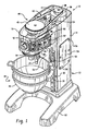
- Fig. 1 is a perspective view of a mixing machine with the top cover removed;
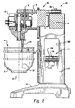
- Fig. 2 is a side elevation of the mixing machine of Fig. 1 in partial cross-section;
- Fig. 3 is a perspective view of an upper portion of the mixing machine of Fig. 1;
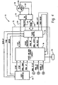
- Fig. 4 is a control system schematic for the mixing machine of Fig. 1;
- Fig. 5 is a side view of the mixing machine showing an exploded view of a control unit
- Fig. 6 is a side view showing the assembled unit partially inserted within an opening of the mixing machine
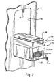
- Fig. 7 is a side view showing the unit in a service position.
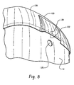
- Fig. 8 is a rear view of a top portion of the mixing machine including the top cover.
- a mixing machine 10 includes a base 12, a mixer body 13 including a column 14 extending upward from the base 10, and a head 16 extending outward from the column 14 and over a bowl receiving location 18.
- the bowl receiving location 18 may be defined by a bowl receiving portion 20 of the mixer body 13, where the bowl receiving portion 20 has spaced apart curved arms 21 defining a curved shape to match the bowl 22.
- the head includes a downwardly extending rotatable output member 24 that can receive a mixer tool such as dough hook, whisk or other tool.
- the head 16 and upper portion of the column 14 typically include a detachable cover (not shown) for enclosing the components.
- the mixing machine includes a drive assembly 26 for effecting rotation of the rotatable output member 24.
- the drive assembly is formed in part by a gear system 28 within the head 16 and having an upwardly extending input drive shaft 30.
- the gear system 28 may take the form of a planetary gear system, in which case the rotatable output member 24 rotates about its own axis 32, with the axis 32 orbiting around a central bowl axis 34.
- a drive motor 36 that is mounted and located in line with the column 14 and includes an upwardly extending output shaft 38.
- a drive linkage 40 connects the motor output shaft 38 to the gear system input shaft 30 and may be formed by the illustrated belt 42 and pulleys 44 and 46.
- Alternative drive linkages could take the form of chain and sprocket combinations, additional gearing and/or bar-type linkages.
- the illustrated drive linkage 40 is a fixed linkage, meaning that the drive ratio between the motor output shaft 38 and the gear system input shaft 30 does not change.
- the bowl receiving portion 20 may be mounted for movement between a raised position toward the head 16 and a lowered position away from the head 16, the raised position being used during mixing operations and the lowered position being used for bowl installation and removal as well as for installation and removal of mixing tools on the rotatable output member 24.
- the curved arms 21 of the bowl receiving portion 20 connect with a central support 50 and the support 50 rides upward and downward on a pair of spaced apart guide rails 52 on the front side of the column 14.
- a power lift mechanism 54 such as a linear actuator, may be provided for effecting upward and downward movement of the bowl receiving portion 20.
- a suitable linear actuator is the Warner Electric DC24-10A5 series DC motor 8" stroke length gear train and ACME screw actuator.
- a top portion 56 of the linear actuator may be secured to mounts 58 unitary with an internal casting of the head, and a lower moving arm or rod portion 60 may be connected to mounts 62 on the support 50 as shown in Fig. 3. In both places a corresponding pin 57 or 61 extending respectively through top portion 56 and moving rod portion 60 can be used for connection to the respective mounts 58 and 62.
- the moving arm or rod portion 60 extends from a housing portion 63.
- a switched reluctance motor is provided as the drive motor 36.
- a switched reluctance motor is desirable because it can provide high torque at low operating speeds, such as those often used in mixing applications for planetary mixers.
- an AC induction motor might be used.
- an exemplary control arrangement for a switched reluctance motor embodiment includes a control system 70 formed by a control unit 72 and a switched reluctance ("SR") drive 74.
- the control unit 72 includes a processor or microcontroller based timer control unit 76 and an analog control circuit 78.
- a user interface 80 enables a user to input desired operations to the control unit 72, and a plurality of sensors S1, S2, and S3 are also connected with the control unit 72 and indicate the status of various parts of the mixer as will be described in more detail below.
- a variable frequency AC drive could be used in place of the SR drive 74.
- an exemplary user interface 80 is located on the head 16 and includes a plurality of input mechanisms including a bowl up/down switch 82 for activating the power bowl lift mechanism 54, a time input mechanism 84 and associated LED display 86 for inputting a desired mix time, a speed input mechanism 88 and associated LED display 90 for inputting a desired mix speed, a mix start button 92 and a mix stop button 94.
- a side of the column 14 includes an opening 100 therethrough.
- Portions of the control system 70 can be formed as a unit 102 that is insertable in the opening, and is mounted for movement between an operating position (e.g., Fig. 3) within the column and a service position (e.g., Fig. 2 and Fig. 7) in which at least part of the unit 102 extends outward from the opening 100 to provide access to the portions of the control system forming the unit 102.
- the unit 102 includes the SR drive 74 and much of the analog control circuit 78, with the timer control unit 76 formed as a separate board located within the head 16 at the interior side of the user interface 80.
- the opening 100 could be formed on any one of the front side, rear side or either lateral side of the column 14.
- FIG. 5 The partially exploded view of Fig. 5 shows a mount panel 104 to which the SR drive 74 with associated heat sink 106, which may be aluminum cast, and control board 108 are attached, along with a transformer 110 and contactor 112 (both shown as blocks for simplicity).
- the mount panel 104 may be a stainless steel plate, but could also be formed of some other material.
- the heat sink 106 is mounted directly to a top side of the mount panel 104 using appropriate fasteners and the control board 108 is mounted in a spaced apart relationship from the heat sink 106 via mount posts 114.
- the transformer 110 and contactor 112 may be connected to the underside of the mount panel 104 using suitable fasteners as well.
- a fuse holder and other applicable components may also be mounted on the underside of mount panel 104.
- the heat sink 106 includes a plurality of fins 116 and a fan 118 (shown in dashed lines) positioned to blow air along the fins 116 for cooling.
- the mount panel 104, fins 116, and control board 108 are all arranged substantially vertical when the unit 102 is in the upright operating position of Fig. 3.
- the fan 118 blows air upward along the fins 116 when the unit 102 is in this operating position.
- the drive motor 36 may also include an integrated fan blowing air upward over the notor windings.
- An upper portion of the column may include an opening for ventilation purposes. In one embodiment, shown in Fig.
- a ventilation opening 122 is formed by a protruding channel 124 formed in the top cover 120 to be spaced away from the outer shell or skin of the column 14.
- a power cord opening 126 is also shown.
- the top 128 of the column 14 is shown in dashed line.
- the unit 102 is configured for pivotal movement between the operating position and the service position.
- the mount panel 104 includes an offset bend 130 at one end thereof.
- a fixed lateral support panel 132 is provided and includes a slot 134 formed therein.
- the slot 134 receives the offset bend portion 130 of the mount panel 104 allowing the mount panel 104 to be pivoted or rotated between the upright operating position and the lateral service position.
- the offset bend 130 limits downward movement of the mount panel 104 within the slot 134, but allows the mount panel 104 to be easily removed from the slot 134 if desired.
- the lateral support panel 132 may be mounted to a plurality of upright supports within the column 14.
- Brackets 136 and 138 are provided within the column and corresponding flanges 140 and 142 are provided on the unit 102 such that when the unit 102 is in the operating position flange 140 aligns with bracket 136 and flange 142 aligns with bracket 138.
- the lower bracket 136 may be formed as a unitary upright bent portion of the lateral support panel 132
- the upper bracket 138 may be formed unitary with an upper panel (not shown)
- the flanges 140 and 142 may each be formed as unitary bent portions of the mount panel 104.
- the respective flanges and brackets can be formed with openings that align to permit fasteners 144 and 146 to be passed therethrough in order to secure the unit 102 in the operating position.
- Bolt and nut combinations could be used as fasteners, but other types of fasteners could also be used.
- the underside of the mount panel When in the service position the underside of the mount panel may rest on lower edge 148 of the opening 100, with the offset bend 130 remaining in the slot 134 to prevent the unit 102 from falling out of the opening 100. Additionally, the transformer 110 and the contactor 112 are mounted far enough out on the underside of the mount panel 104 so as to be clear of the opening 102 and positioned on the outside of the column 14.
- the various portions of the control system 70 integrated into unit 102 require electrical and electronic attachment to other parts of the mixing device.
- the timer control unit 76 will require connection with both.
- the drive motor 36 will require electrical connection with the SR drive 74.
- the transformer 110 will require connection with the incoming power.
- the SR drive 74, transformer 110 and contactor 112 include a plurality of wiring connectors for making both electronic and electrical connections.
- the control board 108 may include a communication cable and connector 150 for connection with a similar cable and connector (not shown ) extending from the timer control unit 76, and cables and connectors 152 may be provided for connection with the drive motor 36.
- the transformer 110 and contactor 112 may have similar cables and connectors, or may simply include terminals to which connectors from other parts of the mixer are connected.
- the unit 102 may be formed during manufacture, prior to installation in the column 14. The unit 102 is then inserted through the opening 100 so as to be located internally of the mixer column 14. During this step the unit 102 may be moved in laterally and then pivoted slightly upward to position in the offset bend 130 of the mount panel 104 into the slot 134. The unit can then be pivoted back down to its service position to facilitate interconnecting the motor wiring connectors with corresponding connectors 152 on the unit 102 and interconnecting the user interface wiring connectors (e.g., connectors from the timer control unit 76 and connectors from the time input mechanism 84 and speed input mechanism 86) to corresponding connectors 150 on the unit.
- the user interface wiring connectors e.g., connectors from the timer control unit 76 and connectors from the time input mechanism 84 and speed input mechanism 86
- the unit 102 can then be pivoted upward to its operating position and secured to the brackets 136 and 138.
- a cover 154 is thereafter placed over the opening 100 and connected by a plurality of fasteners 156.
- a gasket (not shown) may be provided between the cover 154 and the side of the column 14.
Landscapes
- Engineering & Computer Science (AREA)
- Mechanical Engineering (AREA)
- Food Science & Technology (AREA)
- Food-Manufacturing Devices (AREA)
- Mixers Of The Rotary Stirring Type (AREA)
- Processing And Handling Of Plastics And Other Materials For Molding In General (AREA)
- Confectionery (AREA)
Applications Claiming Priority (2)
| Application Number | Priority Date | Filing Date | Title |
|---|---|---|---|
| US10/328,536 US6953278B2 (en) | 2002-12-23 | 2002-12-23 | Mixing machine with accessible internal control unit |
| US328536 | 2002-12-23 |
Publications (2)
| Publication Number | Publication Date |
|---|---|
| EP1433408A2 true EP1433408A2 (fr) | 2004-06-30 |
| EP1433408A3 EP1433408A3 (fr) | 2006-01-04 |
Family
ID=32469018
Family Applications (1)
| Application Number | Title | Priority Date | Filing Date |
|---|---|---|---|
| EP03025468A Withdrawn EP1433408A3 (fr) | 2002-12-23 | 2003-11-06 | Machine à mélanger avec unité de commande interne accessible |
Country Status (7)
| Country | Link |
|---|---|
| US (1) | US6953278B2 (fr) |
| EP (1) | EP1433408A3 (fr) |
| CN (1) | CN1509611A (fr) |
| AU (1) | AU2003271306B2 (fr) |
| CA (1) | CA2451497C (fr) |
| MX (1) | MXPA03011823A (fr) |
| TW (1) | TWI296209B (fr) |
Families Citing this family (36)
| Publication number | Priority date | Publication date | Assignee | Title |
|---|---|---|---|---|
| US6966691B2 (en) * | 2000-04-28 | 2005-11-22 | Premark Feg L.L.C. | Mixer with pivotable bowl |
| US8251567B2 (en) * | 2000-04-28 | 2012-08-28 | Premark Feg L.L.C. | Mixer with pivotable bowl |
| US6991363B2 (en) * | 2000-04-28 | 2006-01-31 | Premark Feg L.L.C. | Mixer with pivotable bowl |
| US7207711B2 (en) * | 2002-12-23 | 2007-04-24 | Premark Feg L.L.C. | Mixing device with variable speed drive and related control features |
| US7273315B2 (en) * | 2002-12-23 | 2007-09-25 | Premark Feg Llc | Mixing device with variable speed drive and related control features |
| US6883959B2 (en) * | 2002-12-23 | 2005-04-26 | Premark Feg L.L.C. | Power bowl lift, motor mount and tensioner for mixing machine |
| DE602005009534D1 (de) * | 2004-05-07 | 2008-10-16 | Premark Feg Llc | Rührgerät mit schwenkbarer schüssel |
| USD540113S1 (en) * | 2004-11-09 | 2007-04-10 | Premark Feg L.L.C. | Mixer |
| ES2265774B1 (es) * | 2005-07-29 | 2008-01-16 | Roberto Brisciani | Gestor electronico para amasadoras de masa panificable y metodo de funcionamiento. |
| USD560434S1 (en) * | 2005-08-29 | 2008-01-29 | Bsh Bosch Und Siemens Hausgeraete Gmbh | Container for kitchen machine |
| US7950843B2 (en) * | 2008-01-23 | 2011-05-31 | Premark Feg L.L.C. | Mixing machine and associated bowl support arrangement |
| US8182135B2 (en) * | 2009-01-22 | 2012-05-22 | Premark Feg L.L.C. | Mixing machine with bowl support |
| USD603214S1 (en) * | 2009-03-23 | 2009-11-03 | Premark Feg L.L.C. | Mixing apparatus |
| USD677520S1 (en) * | 2012-04-04 | 2013-03-12 | Zwilling J. A. Henckets AG | Mixer |
| USD683578S1 (en) * | 2012-04-13 | 2013-06-04 | Electrolux Professional S.P.A. | Mixer |
| CN106509006A (zh) * | 2016-09-13 | 2017-03-22 | 范广志 | 一种和面机 |
| DE112018001062T5 (de) | 2017-02-28 | 2019-11-07 | Illinois Tool Works Inc. | Rührmaschine mit vfd-basierter diagnose |
| US11052360B2 (en) | 2017-02-28 | 2021-07-06 | Illinois Tool Works Inc. | Mixing machine system |
| GB2572930B (en) | 2017-02-28 | 2022-03-09 | Illinois Tool Works | Mixing machine system |
| USD850221S1 (en) * | 2017-03-10 | 2019-06-04 | Eternal East (HK) Ltd. | Nut milk maker |
| USD878847S1 (en) | 2017-09-06 | 2020-03-24 | Eternal East (HK) Ltd. | Nut milk maker |
| WO2019103886A1 (fr) | 2017-11-21 | 2019-05-31 | Illinois Tool Works Inc. | Machine de mélange pourvue d'un système de glissière avec support de bol mélangeur |
| WO2019126436A2 (fr) | 2017-12-21 | 2019-06-27 | Illinois Tool Works Inc. | Machine de mélange |
| CN110839669A (zh) * | 2019-11-27 | 2020-02-28 | 湖南省爱尚乐心食品有限公司 | 一种和面升降搅拌机构 |
| USD985331S1 (en) * | 2020-12-31 | 2023-05-09 | Sharkninja Operating Llc | Housing for a micro puree machine |
| US12016493B2 (en) | 2020-12-31 | 2024-06-25 | Sharkninja Operating Llc | Micro puree machine |
| US11154163B1 (en) | 2020-12-31 | 2021-10-26 | Sharkninja Operating Llc | Micro puree machine |
| USD983603S1 (en) | 2020-12-31 | 2023-04-18 | Sharkninja Operating Llc | Blade for a micro puree machine |
| US12016496B2 (en) | 2020-12-31 | 2024-06-25 | Sharkninja Operating Llc | Micro puree machine |
| USD985334S1 (en) | 2020-12-31 | 2023-05-09 | Sharkninja Operating Llc | Nested bowl for a micro puree machine |
| US11925298B2 (en) | 2020-12-31 | 2024-03-12 | Sharkninja Operating Llc | Micro puree machine |
| US11641978B2 (en) | 2020-12-31 | 2023-05-09 | Sharkninja Operating Llc | Micro puree machine |
| US11871765B2 (en) | 2020-12-31 | 2024-01-16 | Sharkninja Operating Llc | Micro puree machine |
| US12064056B2 (en) | 2020-12-31 | 2024-08-20 | Sharkninja (Hong Kong) Company Limited | Micro puree machine |
| CN112956506B (zh) * | 2021-03-08 | 2024-02-20 | 神池饼业食品有限公司 | 一种加工用小型麻花制作设备 |
| US12575698B2 (en) | 2021-07-12 | 2026-03-17 | Sharkninja Operating Llc | Micro puree machine with selectable food processing routines and automated motor control |
Family Cites Families (26)
| Publication number | Priority date | Publication date | Assignee | Title |
|---|---|---|---|---|
| US2789798A (en) * | 1952-12-30 | 1957-04-23 | Hoover Co | Folding food mixers |
| US3224743A (en) * | 1961-11-16 | 1965-12-21 | Ronson Corp | Multipurpose domestic appliance |
| US3934758A (en) * | 1974-03-14 | 1976-01-27 | Kipp Frederick M | Refrigerated beverage dispenser-mixer |
| US4325643A (en) * | 1980-07-11 | 1982-04-20 | Sunbeam Corporation | Food-mixing apparatus comprising a driving unit and a separable arm |
| NL8300452A (nl) * | 1983-02-07 | 1984-09-03 | Philips Nv | Keukenmachine. |
| US4819460A (en) * | 1986-06-18 | 1989-04-11 | Emerson Electric Co. | Washing machine with direct drive system |
| US4697929A (en) * | 1986-10-28 | 1987-10-06 | Charles Ross & Son Company | Planetary mixers |
| US4822172A (en) * | 1987-12-23 | 1989-04-18 | Whirlpool Corporation | Electric food mixer |
| FI90732C (fi) * | 1989-05-09 | 1994-03-25 | Ahlstroem Oy | Sekoitin |
| US5000578A (en) * | 1990-03-02 | 1991-03-19 | Sunbeam Corporation | Food mixing appliance |
| EP0739166A1 (fr) * | 1992-03-30 | 1996-10-30 | Premark FEG L.L.C. | Mixer a support de bol verticalement mobile |
| US5348393A (en) * | 1992-07-24 | 1994-09-20 | Univex Corporation | Safety guard system for food mixer |
| US5306083A (en) * | 1993-08-04 | 1994-04-26 | Premark Feg Corporation | Mixer guard mounting means |
| GB9422270D0 (en) * | 1994-11-04 | 1994-12-21 | Hobart Mfg Co | Variable speed food mixer |
| GB9414005D0 (en) * | 1994-07-12 | 1994-08-31 | Switched Reluctance Drives Ltd | Switched electric machine controller |
| CA2151532C (fr) * | 1994-07-25 | 1998-12-22 | Emerson Electric Co. | Moteur a reluctance commutable muni d'un demarreur auxiliaire |
| FR2738083B1 (fr) * | 1995-08-25 | 1997-09-19 | Gec Alsthom T & D Sa | Armoire de commande locale pour appareillage electrique |
| DE19533161A1 (de) * | 1995-09-08 | 1997-03-13 | Philips Patentverwaltung | Elektrischer Antrieb |
| US5957021A (en) * | 1995-10-10 | 1999-09-28 | Black & Decker, Inc. | Guard and control apparatuses for sliding compound miter saw |
| US5653535A (en) * | 1996-02-28 | 1997-08-05 | Premark Feg L.L.C. | Mixing machine |
| GB9714696D0 (en) * | 1997-07-11 | 1997-09-17 | Switched Reluctance Drives Ltd | Exercise apparatus |
| US5934802A (en) | 1997-09-15 | 1999-08-10 | Premark Feg L.L.C. | Planetary gear system for mixer |
| US5906432A (en) * | 1997-09-19 | 1999-05-25 | American Ingredients Company | Dough mixer apparatus for laboratory testing of the development of a dough sample |
| US6991363B2 (en) * | 2000-04-28 | 2006-01-31 | Premark Feg L.L.C. | Mixer with pivotable bowl |
| AUPR561101A0 (en) * | 2001-06-12 | 2001-07-12 | Sunbeam Corporation Limited | Food mixer |
| US6612732B2 (en) * | 2001-10-19 | 2003-09-02 | Fluid Management, Inc. | Paint mixer |
-
2002
- 2002-12-23 US US10/328,536 patent/US6953278B2/en not_active Expired - Fee Related
-
2003
- 2003-11-06 EP EP03025468A patent/EP1433408A3/fr not_active Withdrawn
- 2003-12-01 CA CA002451497A patent/CA2451497C/fr not_active Expired - Fee Related
- 2003-12-08 TW TW092134615A patent/TWI296209B/zh not_active IP Right Cessation
- 2003-12-18 MX MXPA03011823A patent/MXPA03011823A/es active IP Right Grant
- 2003-12-19 CN CNA2003101215407A patent/CN1509611A/zh active Pending
- 2003-12-22 AU AU2003271306A patent/AU2003271306B2/en not_active Ceased
Also Published As
| Publication number | Publication date |
|---|---|
| CA2451497C (fr) | 2008-10-14 |
| EP1433408A3 (fr) | 2006-01-04 |
| MXPA03011823A (es) | 2004-07-01 |
| TW200416068A (en) | 2004-09-01 |
| AU2003271306B2 (en) | 2005-03-17 |
| AU2003271306A1 (en) | 2004-07-08 |
| CN1509611A (zh) | 2004-07-07 |
| US20040120213A1 (en) | 2004-06-24 |
| CA2451497A1 (fr) | 2004-06-23 |
| TWI296209B (en) | 2008-05-01 |
| US6953278B2 (en) | 2005-10-11 |
Similar Documents
| Publication | Publication Date | Title |
|---|---|---|
| US6953278B2 (en) | Mixing machine with accessible internal control unit | |
| US5518370A (en) | Portable electric fan with swivel mount | |
| AU2005201957B2 (en) | Mixing device with variable speed drive and related control features | |
| CA2451494C (fr) | Melangeur avec entrainement a vitesse variable et fonctions de commande connexes | |
| JP2000074477A (ja) | 空気調和機 | |
| MX2007010791A (es) | Maquina mezcladora, cubierta de cabezal mezclador asociada y metodo de ensamble. | |
| US8662984B2 (en) | Gaming machine and gaming machine reel assembly | |
| US6708603B1 (en) | Frying pot | |
| CN113797820A (zh) | 搅拌机 | |
| US7160022B2 (en) | Paint stirring machine and method for mounting same | |
| CN210723857U (zh) | 一种便于散热的动力配电箱 | |
| JP2005510387A5 (fr) | ||
| EP1790322A1 (fr) | Jacuzzi | |
| CN109381064A (zh) | 机座组件及食物处理机 | |
| CN219815951U (zh) | 搅拌机构及其搅拌设备 | |
| US20260033671A1 (en) | Locking mechanism for a tilt head mixer | |
| CN222075020U (zh) | 一种齿轮箱传动系统及厨师机 | |
| CN223539216U (zh) | 一种售卖机微波加热模组 | |
| CN216327854U (zh) | 一种便捷式金属铸件加工用定位装置 | |
| US2016554A (en) | Culinary appliance | |
| KR100186407B1 (ko) | 전자유도가열밥솥의 제어기 냉각장치 | |
| JP2004044941A (ja) | 加熱調理器 | |
| JP2012237521A (ja) | 加熱調理器 | |
| CN210354417U (zh) | 煎烤机 | |
| CN208259612U (zh) | 机座组件及食物处理机 |
Legal Events
| Date | Code | Title | Description |
|---|---|---|---|
| PUAI | Public reference made under article 153(3) epc to a published international application that has entered the european phase |
Free format text: ORIGINAL CODE: 0009012 |
|
| AK | Designated contracting states |
Kind code of ref document: A2 Designated state(s): AT BE BG CH CY CZ DE DK EE ES FI FR GB GR HU IE IT LI LU MC NL PT RO SE SI SK TR |
|
| AX | Request for extension of the european patent |
Extension state: AL LT LV MK |
|
| PUAL | Search report despatched |
Free format text: ORIGINAL CODE: 0009013 |
|
| AK | Designated contracting states |
Kind code of ref document: A3 Designated state(s): AT BE BG CH CY CZ DE DK EE ES FI FR GB GR HU IE IT LI LU MC NL PT RO SE SI SK TR |
|
| AX | Request for extension of the european patent |
Extension state: AL LT LV MK |
|
| 17P | Request for examination filed |
Effective date: 20060520 |
|
| AKX | Designation fees paid |
Designated state(s): DE FR GB |
|
| GRAP | Despatch of communication of intention to grant a patent |
Free format text: ORIGINAL CODE: EPIDOSNIGR1 |
|
| STAA | Information on the status of an ep patent application or granted ep patent |
Free format text: STATUS: THE APPLICATION IS DEEMED TO BE WITHDRAWN |
|
| 18D | Application deemed to be withdrawn |
Effective date: 20070424 |