EP1433497B1 - Aktive implantierbare medizinische Vorrichtung mit Detektierung von evozierten Herzpotentialen, insbesondere Atrialpotentialen - Google Patents
Aktive implantierbare medizinische Vorrichtung mit Detektierung von evozierten Herzpotentialen, insbesondere Atrialpotentialen Download PDFInfo
- Publication number
- EP1433497B1 EP1433497B1 EP03293303A EP03293303A EP1433497B1 EP 1433497 B1 EP1433497 B1 EP 1433497B1 EP 03293303 A EP03293303 A EP 03293303A EP 03293303 A EP03293303 A EP 03293303A EP 1433497 B1 EP1433497 B1 EP 1433497B1
- Authority
- EP
- European Patent Office
- Prior art keywords
- stimulation
- amplifier
- period
- blanking
- terminal
- Prior art date
- Legal status (The legal status is an assumption and is not a legal conclusion. Google has not performed a legal analysis and makes no representation as to the accuracy of the status listed.)
- Expired - Lifetime
Links
- 230000000747 cardiac effect Effects 0.000 title claims abstract description 14
- 230000000763 evoking effect Effects 0.000 title claims description 34
- 238000001514 detection method Methods 0.000 title claims description 30
- 230000001746 atrial effect Effects 0.000 title description 6
- 230000000638 stimulation Effects 0.000 claims abstract description 79
- 230000036279 refractory period Effects 0.000 claims description 11
- 239000000523 sample Substances 0.000 claims description 9
- 230000002269 spontaneous effect Effects 0.000 claims description 8
- 238000004458 analytical method Methods 0.000 claims description 6
- 238000007599 discharging Methods 0.000 claims 5
- 239000003990 capacitor Substances 0.000 description 9
- 230000001052 transient effect Effects 0.000 description 6
- 238000000034 method Methods 0.000 description 5
- 230000010287 polarization Effects 0.000 description 4
- 230000002861 ventricular Effects 0.000 description 4
- 238000010586 diagram Methods 0.000 description 3
- 210000004165 myocardium Anatomy 0.000 description 3
- 230000005540 biological transmission Effects 0.000 description 2
- 210000002837 heart atrium Anatomy 0.000 description 2
- 238000012163 sequencing technique Methods 0.000 description 2
- 238000004088 simulation Methods 0.000 description 2
- 230000004936 stimulating effect Effects 0.000 description 2
- 206010003658 Atrial Fibrillation Diseases 0.000 description 1
- 241000287107 Passer Species 0.000 description 1
- 230000002238 attenuated effect Effects 0.000 description 1
- 208000037265 diseases, disorders, signs and symptoms Diseases 0.000 description 1
- 230000000694 effects Effects 0.000 description 1
- 210000005003 heart tissue Anatomy 0.000 description 1
- 239000007943 implant Substances 0.000 description 1
- 230000002401 inhibitory effect Effects 0.000 description 1
- 230000010354 integration Effects 0.000 description 1
- 230000028161 membrane depolarization Effects 0.000 description 1
- 230000002107 myocardial effect Effects 0.000 description 1
- 238000006386 neutralization reaction Methods 0.000 description 1
- 230000002035 prolonged effect Effects 0.000 description 1
- 238000011084 recovery Methods 0.000 description 1
- 230000033764 rhythmic process Effects 0.000 description 1
- 230000009163 spontaneous depolarization Effects 0.000 description 1
Images


Classifications
-
- A—HUMAN NECESSITIES
- A61—MEDICAL OR VETERINARY SCIENCE; HYGIENE
- A61N—ELECTROTHERAPY; MAGNETOTHERAPY; RADIATION THERAPY; ULTRASOUND THERAPY
- A61N1/00—Electrotherapy; Circuits therefor
- A61N1/18—Applying electric currents by contact electrodes
- A61N1/32—Applying electric currents by contact electrodes alternating or intermittent currents
- A61N1/36—Applying electric currents by contact electrodes alternating or intermittent currents for stimulation
- A61N1/362—Heart stimulators
- A61N1/37—Monitoring; Protecting
- A61N1/371—Capture, i.e. successful stimulation
Definitions
- the invention relates to "active implantable medical devices" as defined by the Council of the European Communities Directive 90/385 / EEC of 20 June 1990, more specifically pacemaker, defibrillator and / or cardioverter devices enabling delivery to the heart of Low energy electrical impulses for the treatment of cardiac rhythm disorders.
- All these devices comprise activity detection means, that is to say, detection of spontaneous depolarizations of the myocardium, as well as means for stimulating this myocardium.
- the stimulation After the stimulation, it is important to be able to collect the "evoked wave", that is to say the depolarization wave induced by the stimulation of the cavity considered, in order to determine if this stimulation was effective or not, for example to adjust the amplitude and / or the width of the stimulation pulse.
- the "evoked wave” that is to say the depolarization wave induced by the stimulation of the cavity considered
- the difficulty lies in the fact that the evoked wave is very early and that at the output of the detection amplifier it is mixed, or even embedded, in the electrical transient called “response of the amplifier” consecutive to the electrical stimulation.
- This response is always present independently of the presence of a wave evoked or not, and depends only on the electrical characteristics of the amplifier itself, the energy contained in the stimulation pulse (amplitude and width) as well as impedance characteristics of the core / electrode interface, called “polarization of the probe".
- the evoked wave is even more difficult in the case of atrial pacing. Indeed, the evoked wave then has a much smaller amplitude than in the case of the ventricle, and it is also much earlier: thus, the auricular evoked wave (P wave) appears about 10 ms after stimulation to end at approximately 30 ms, whereas the ventricular evoked wave (R wave) is observed approximately 60 ms after the stimulation.
- P wave auricular evoked wave
- R wave ventricular evoked wave
- One of the aims of the invention is to remedy this difficulty by proposing a new technique for detecting the evoked P wave, taking into account the very early and low amplitude nature of the latter.
- the invention is not limited to the collection of the evoked wave P, but can be applied as well, given the multiple advantages it provides, to the collection of evoked R waves (ventricular waves), by example in the case of a ventricular capture test.
- the technique for detecting the evoked wave according to the invention is able to overcome the polarization of the probe regardless of the useful energy level of the stimulation pulse, by allowing detection of a possible P wave during a period, called "listening period", both very early and prolonged, for example typically ranging from 6 ms to 40 ms after the stimulation in the case where the Stimulated cavity is the atrium.
- the device of the invention is of a type comprising, in a manner known per se: a terminal adapted to be connected to an intracardiac electrode of a probe implanted in a first cardiac cavity; stimulation means, able to apply a stimulation pulse to the terminal for delivering this pulse to the first cavity; discharge means coupled to the terminal, adapted to short-circuit this terminal for the duration of a discharge period; and at least one stage capable of detecting on the terminal electrical signals corresponding to spontaneous potentials appearing in the first cavity, and comprising an amplifier with an input coupled to the terminal and a output, and blanking means comprising a switch adapted to temporarily decouple the terminal from the input of the amplifier.
- the device further comprises sequencer means able to activate the discharge means, after application of the stimulation pulse, during the duration of the discharge period, then activate the blanking means for at least the duration of the stimulation and the discharge period.
- Such a device is known from WO-A-01/43819.
- the sequencer means after having activated the blanking means a first time during the duration of the stimulation pulse, are able to: activate the discharge means with delay after the application of the stimulation pulse ; then inhibiting the blanking means during a listening period including at least a part of said delay, so as to allow the amplifier to detect, during this listening period, signals corresponding to spontaneous post-stimulation potentials in the first cavity; and finally activate the blanking means a second time after the listening period, during the duration of the discharge period.
- the amplifier is a switchable amplifier between a normal detection mode and a fast desaturation mode, in particular a low cutoff frequency mode and a high cutoff frequency mode, respectively, and the sequencer means are suitable, furthermore , to switch the amplifier to fast desaturation mode for at least the duration of the listening period.
- the sequencer means resumes the amplifier in normal detection mode after the start of the discharge period, and not concomitantly at this beginning.
- the sequencing means control the discharge means so as to end the discharge period before the end of a post-stimulation refractory period of analysis of the signal at the output of the amplifier, for both said first cavity and for at least a second cardiac cavity, so as to avoid false detections in this (these) second (s) cavity (s).
- This refractory period may in particular be a retrigger period retriggerable variable duration depending on the level of disturbance present at the output of the amplifier.
- the device may comprise means for analyzing the signal at the output of the amplifier during the listening period, able to detect the presence of an evoked wave resulting from the stimulation applied to the cavity, so as to discriminate between effective stimulations. and non-effective stimulations.
- the reference 10 denotes the circuit of the invention, with its stimulation stage and its detection stage.
- the stimulation stage comprises a reservoir capacitor 12 charged to a predetermined voltage by a charging circuit 14.
- the energy accumulated in the capacitor 12 is delivered for a predetermined duration (duration of the stimulation pulse) by closing a switch 16 ensuring the transfer of this energy, via a connecting capacitor 18, to a output terminal CATH stimulator, terminal connected for example to the distal electrode of an atrial or ventricular pacing probe.
- This probe and the electrode / myocardium interface together have an impedance schematized at 20, constituting the load impedance of the device (including serial resistance of the probe and the cardiac tissue and the capacity of the interface, called "Helmholtz capacity". ").
- the function of the capacitor 18 is to protect the patient against a possible direct current in the event of failure of the stimulation circuits, for example of the switch 16.
- the pacing pulse typically has an amplitude of between 1.5 and 7.5 V with a pulse width between 0.12 ms and 0.98 ms (the pacing energy is proportional to the width and the square the amplitude of the pulse).
- OCD Output Capacitor Discharge
- a resistor 26, typically 200 kO, makes it possible to complete the discharge of the capacitor 18 after reopening of the switch 24. It also makes it possible to define the overall input impedance of the device for the detection of cardiac signals.
- the detection stage 28 comprises a filter amplifier 30 connected to the CATH terminal via a link capacitor 32 and a controlled switch 34.
- the signal V ampli output of the amplifier 30 is sampled and digitized by an analog / digital converter 36 outputting a digitized signal V num capable of being analyzed by the microcontroller 38 of the device.
- the role of the switch 34 is to ensure an analog "blanking", that is to say a disconnection of the input of the amplifier 30 during the duration of the stimulation and the OCD, in order to avoid too much saturation.
- the potentials during the simulation can indeed reach several volts, those at the beginning of the OCD being of the order of a hundred millivolts.
- the blanking period starts slightly before the stimulation pulse 40 to end slightly after the end of the OCD 42.
- the duration of the blanking is of the order of 14 ms so that the blanking period can completely frame the stimulation and the OCD immediately following this stimulation.
- the input potential of the amplifier is approximately stabilized, but at the output the amplifier has a transient response to the post-blanking reconnection, excluding the detection of an early evoked wave.
- an early evoked wave especially a P wave (atrial) likely to arrive as early as 10 ms after the stimulation, and with moreover a low amplitude and a short duration (typically 10 to 15 ms)
- the evoked wave can be masked during the blanking period or during the period of post-blanking instability, described above, extending about fifteen to twenty milliseconds after the stimulation pulse.
- a significant transient appears at the post-blanking reconnection at the output of the amplifier, which makes it very difficult to detect an atrial evoked wave of small amplitude, very early and very fast.
- the OCD can be analyzed as a relatively weak signal with respect to the stimulation pulse and amplitude very close to that of the endocavitary complexes: in this case, if the discharge of the interface is not Completely complete at the end of the OCD - which is usually the case - the residual slow variation present on the catheter will be amplified significantly and will create significant potential at the time of post-blanking reconnection, preventing easy detection. the presence of an evoked cardiac potential superimposed.
- the basic idea of the present invention is not to perform the OCD immediately after the stimulation, but to shift this phase of discharge. after the appearance period of the evoked wave.
- the offset of the OCD is typically about 40 ms after the stimulation of the atrium.
- the shift of the OCD after stimulation is greater (typically about 60 ms after the stimulation of the ventricle), since the R wave is less early than the P wave.
- the OCD shift should be such that the OCD occurs during the absolute post-ventricular or post-atrial refractory period (PRAPA or PVARP), so as not to cause false detection of spontaneous complexes.
- PRAPA absolute post-ventricular or post-atrial refractory period
- PVARP post-atrial refractory period
- microblanking In addition, to avoid excessive saturation of the amplifier at the time of stimulation, a very short blanking or "microblanking" is performed, starting a few tens of microseconds before the start of the stimulation pulse and ending a few tens of minutes. microseconds after the end of this pulse. This microblanking also makes it possible to protect, as the case may be, the analog input of the detection amplifier against any overload coming from the stimulation pulse.
- the protection microblanking is performed by a component external to the integrated chip of the device, or by a separate high voltage integrated circuit whose integration density may be lower.
- the amplifier 30 used for the detection is advantageously a switchable amplifier in a fast mode of desaturation, called "FRM" ( Fast Recovery Mode ), prior to the stimulation pulse, this mode being maintained during the search for the evoked wave.
- FAM Fast Recovery Mode
- This switching to a fast desaturation mode allows the amplifier to recover faster after the microblanking performed during the stimulation, typically in a time less than 8 ms.
- the FRM mode can be obtained in various ways, for example by increasing the bias current of the amplifier, by resetting some internal gratings to cancel the energy stored in the capacitive components and / or, preferentially and as illustrated here, by increasing the cutoff frequency to a very high value, for example 50 Hz.
- the amplifier is left in FRM mode during the entire listening period of the evoked complex; the evoked signals are then transmitted at the output of the sense amplifier because they are very fast, and they will be processed within the microcontroller 38 by a specific algorithm.
- the sense amplifier is restarted in its Normal listening mode for spontaneous wave detection and ECG recording, as soon as the search period of the evoked complex is over.
- the device leaves the FRM mode of the amplifier just after the start of the OCD (and not concurrently at this beginning), so as not to chain two types of disturbances. Indeed, the return of the FRM mode to the normal mode will generate a significant disturbance of the output of the amplifier, and it is important to always be in a refractory period of the device.
- a retriggerable refractory period system whose duration is automatically adjusted as a function of the disturbance present at the output of the detection amplifier, as described for example in EP-A-0 962 235 (Medical ELA), is preferably used. ).
- a refractory period of 150 ms remains sufficient for medium to low polarization probes.
- the search for the evoked wave uses the particular technique that will now be described.
- the potential V ampli output of the sense amplifier during the search period 52 of the evoked wave comprises a fast transient 50, recovered in about 10 seconds. ms, followed by a quasi-static intermediate level of potential 54.
- This intermediate potential level 54 is however different from the basic potential level 56 at rest.
- the absolute value of the intermediate potential 54 varies according to the nature of the probe and its polarization, so that the detection of the evoked wave can not be done simply by detecting the crossing of a threshold by the signal V amp at the output of the amplifier.
- the system must therefore be calibrated by regularly evaluating the level of the intermediate potential 54 during the life of the implant.
- An advantageous variant of this calibration consists of analyzing the signal samples after digitization to deduce a parameter, for example and preferably, as illustrated in FIGS. 5A and 5B, a second derivative evaluated between two programmable times t 1 and t 2 , included in the period 52 search for spontaneous complexes.
- a second derivative is easy to calculate from digitized samples, so that this technique can be implemented simply by an appropriate algorithm within the microcontroller 38.
- the evoked wave will appear very clearly on examination of the digitized signal in the central zone. This wave, if it is present, appears very distinctly in 58.
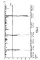
- Figure 6 illustrates a clinical result with alternation of ineffective and effective stimulations.
- the effective stimulations (4 consecutive stimulations) give extrema values (of minima in this case) of the very important second derivative, whereas the inefficient simulations give low values of these extrema.
- the criterion for detecting the evoked wave that is to say the efficiency of the stimulation, then simply results in the crossing of a threshold value V threshold of the second derivative.
- V threshold of the second derivative.
- the cases where the second derivative crosses the threshold undoubtedly correspond to the case where the evoked wave P is present (FIG. 5B); on the other hand, when the stimulation is ineffective (FIG. 5A), the second derivative remains very much below the set threshold.
Landscapes
- Health & Medical Sciences (AREA)
- Cardiology (AREA)
- Heart & Thoracic Surgery (AREA)
- Engineering & Computer Science (AREA)
- Biomedical Technology (AREA)
- Nuclear Medicine, Radiotherapy & Molecular Imaging (AREA)
- Radiology & Medical Imaging (AREA)
- Life Sciences & Earth Sciences (AREA)
- Animal Behavior & Ethology (AREA)
- General Health & Medical Sciences (AREA)
- Public Health (AREA)
- Veterinary Medicine (AREA)
- Electrotherapy Devices (AREA)
Claims (10)
- Aktive implantierbare medizinische Vorrichtung, insbesondere Herzschrittmacher, Defibrillator, Kardioverter oder Multisite-Vorrichtung, mit:- einem Anschluss (CATH), der mit einer intrakardialen Elektrode einer in einem ersten Herzraum implantierten Sonde verbindbar ist;- Stimulationsmitteln (12-18), die geeignet sind, an den Anschluss einen Stimulationsimpuls zur Abgabe dieses Impulses an den ersten Raum anzulegen;- an den Anschluss gekoppelten Entladungsmitteln (24, 26), die geeignet sind, diesen Anschluss während der Dauer einer Entladungsperiode (42, OCD) kurz zu schließen;- wenigstens einer Stufe, die geeignet ist, am Anschluss elektrische Signale zu erfassen, die spontanen Potentialen entsprechen, welche im ersten Raum auftreten, und folgendes umfasst:■ einen Verstärker (30) mit einem an den Anschluss gekappelten Eingang und einem Ausgang, und■ Austastmittel (34), mit einem Taster, der geeignet ist, den Anschluss zeitweise vom Eingang des Verstärkers zu entkoppeln; und- Sequenziermitteln, die geeignet sind, nacheinander:Vorrichtung, die dadurch gekennzeichnet ist, dass, wenn die Sequenziermittel die Austastmittel ein erstes Mal (Mikro-Austasten) während der Dauer des Stimulationsimpulses (40) aktiviert haben, die Sequenziermittel außerdem geeignet sind:■ die Entladungsmittel in Antwort an das Anlegen des Stimulationsimpulses (40) während der Dauer der Entladungsperiode zu aktivieren, und■ die Austastmittel während wenigstens der Dauer der Stimulation und der Entladungsperiode zu aktivieren,■ die Entladungsmittel mit Verzögerung nach Anlegen des Stimulationsimpulses zu aktivieren, sodann■ die Austastmittel während einer Abhörperiode (44) zu hemmen, die wenigstens einen Teil der Verzögerung umfasst, um so während dieser Abhörperiode die Erfassung von Signalen durch den Verstärker zu erfauben, die spontanen Potentialen nach der Stimulation im ersten Raum entsprechen, und schließlich■ die Austastmittel ein zweites Mal (Austasten) nach der Abhörperiode während der Dauer der Entladungsperiode (42, OCD) zu aktivieren.
- Vorrichtung nach Anspruch 1, in welcher:- der Verstärker (30) ein Verstärker ist, der zwischen einem normalen Erfassungsmodus und einem Modus schneller Entsättigung umschaltbar ist, und- die Sequenziermittel außerdem geeignet sind, den Verstärker wenigstens während der Dauer der Abhörperiode in den Modus schneller Entsättigung umzuschalten.
- Vorrichtung nach Anspruch 2, in welcher der normale Erfassungsmodus ein Modus mit einer niedrigen Grenzfrequenz ist und der Modus schneller Entsättigung ein Modus mit einer hohen Grenzfrequenz ist.
- Vorrichtung nach Anspruch 2, in welcher die Sequenziermittel geeignet sind, den Verstärker nach dem Beginn der Entladungsperiode in den normalen Erfassungsmodus zurückzuschalten, auf zu diesem Beginn nicht gleichzeitige Weise.
- Vorrichtung nach Anspruch 1, in welcher die Sequenziermittel die Entladungsmittel befehligen, um so die Entladungsperiode vor dem Ende einer unempfänglichen, post-stimulativen Periode zur Analyse des Signals am Ausgang des Verstärkers zu beenden.
- Vorrichtung nach Anspruch 5, in welcher die Sequenziermittel die Entladungsperiode vor dem Ende einer unempfänglichen, post-stimulativen Periode zur Analyse des Signals am Ausgang des Verstärkers beenden, sowohl für den ersten Raum wie auch für wenigstens einen zweiten Herzraum, um so Falscherkennungen in diesem (diesen) zweiten Raum(Räumen) zu vermeiden.
- Vorrichtung nach Anspruch 5, in welcher die unempfängliche Periode eine wieder auslösbare unempfängliche Periode ist, von in Abhängigkeit des am Ausgang des Verstärkers vorhandenen Störungsniveaus veränderlicher Dauer.
- Vorrichtung nach Anspruch 1, mit Mitteln zur Analyse des Signals am Ausgang des Verstärkers während der Abhörperiode, die geeignet sind, das Vorliegen einer im Anschluss an die an den Raum angelegte Stimulation gebildeten Welle zu erfassen, um so zwischen wirksamen Stimulationen und unwirksamen Stimulationen zu unterscheiden.
- Vorrichtung nach Anspruch 8, in welcher die Analysemittel Mittel umfassen, die geeignet sind, die Veränderungen einer Ableitung der Ordnung n, mit n = 1, vorzugsweise n = 2, des Signals am Ausgang des Verstärkers zu analysieren.
- Vorrichtung nach Anspruch 9, in welcher die Analysemittel außerdem Mittel umfassen, die geeignet sind, die Durchschreitung eines Schwellenwerts (Vschwelle) durch einen Extremwert der Ableitung des Signals am Ausgang des Verstärkers zu erfassen.
Applications Claiming Priority (2)
| Application Number | Priority Date | Filing Date | Title |
|---|---|---|---|
| FR0216724A FR2849387B1 (fr) | 2002-12-26 | 2002-12-26 | Dispositif medical implantable actif tel que stimulateur cardiaque, defibrillateur, cardioverteur ou dispositif multisite, a detection des potentiels evoques post-stimulation, notamment auriculaires |
| FR0216724 | 2002-12-26 |
Publications (2)
| Publication Number | Publication Date |
|---|---|
| EP1433497A1 EP1433497A1 (de) | 2004-06-30 |
| EP1433497B1 true EP1433497B1 (de) | 2006-05-03 |
Family
ID=32406531
Family Applications (1)
| Application Number | Title | Priority Date | Filing Date |
|---|---|---|---|
| EP03293303A Expired - Lifetime EP1433497B1 (de) | 2002-12-26 | 2003-12-23 | Aktive implantierbare medizinische Vorrichtung mit Detektierung von evozierten Herzpotentialen, insbesondere Atrialpotentialen |
Country Status (5)
| Country | Link |
|---|---|
| US (1) | US7203544B2 (de) |
| EP (1) | EP1433497B1 (de) |
| AT (1) | ATE324929T1 (de) |
| DE (1) | DE60304984T2 (de) |
| FR (1) | FR2849387B1 (de) |
Families Citing this family (6)
| Publication number | Priority date | Publication date | Assignee | Title |
|---|---|---|---|---|
| FR2888511A1 (fr) * | 2005-07-12 | 2007-01-19 | Ela Medical Soc Par Actions Si | Dispositif medical implantable actif de type prothese cardiaque comprenant des moyens perfectionnes de discrimination entre stimulations auriculaires efficaces et non efficaces |
| US20100089067A1 (en) * | 2008-10-10 | 2010-04-15 | General Electric Company | Adaptive performance model and methods for system maintenance |
| ATE511881T1 (de) * | 2008-11-19 | 2011-06-15 | Ela Medical Sa | Aktives medizinisches implantat, das mit testmitteln zur aurikulären datenerfassung ausgestattet ist |
| US10905884B2 (en) | 2012-07-20 | 2021-02-02 | Cardialen, Inc. | Multi-stage atrial cardioversion therapy leads |
| JP6791659B2 (ja) * | 2016-06-16 | 2020-11-25 | 日本光電工業株式会社 | 生体電位測定装置 |
| CN113346466B (zh) * | 2021-06-22 | 2022-11-15 | 国网重庆市电力公司 | 一种计及对地电容的逆变型电站单相接地故障保护方法 |
Family Cites Families (10)
| Publication number | Priority date | Publication date | Assignee | Title |
|---|---|---|---|---|
| US4498478A (en) * | 1982-09-13 | 1985-02-12 | Medtronic, Inc. | Apparatus for reducing polarization potentials in a pacemaker |
| US4727877A (en) * | 1984-12-18 | 1988-03-01 | Medtronic, Inc. | Method and apparatus for low energy endocardial defibrillation |
| US4674509A (en) * | 1985-05-28 | 1987-06-23 | Cordis Corporation | System and method for detecting evoked cardiac contractions |
| US4825870A (en) * | 1987-06-19 | 1989-05-02 | Siemens-Pacesetter, Inc. | Pacemaker having crosstalk protection feature |
| US5391188A (en) * | 1992-05-01 | 1995-02-21 | Medtronic, Inc. | Low cost implantable medical device |
| US5265602A (en) * | 1992-07-13 | 1993-11-30 | Medtronic, Inc. | Ring-to-ring cardiac electrogram pacemaker |
| US5562595A (en) * | 1995-08-17 | 1996-10-08 | Medtronic, Inc. | Multiple therapy cardiac assist device having battery voltage safety monitor |
| US5662689A (en) * | 1995-09-08 | 1997-09-02 | Medtronic, Inc. | Method and apparatus for alleviating cardioversion shock pain |
| FR2779353B1 (fr) * | 1998-06-05 | 2000-07-13 | Ela Medical Sa | Dispositif medical implantable actif a gestion perfectionnee des periodes refractaires |
| WO2001043819A1 (en) * | 1999-12-14 | 2001-06-21 | Cardiac Pacemakers, Inc. | Autocapture pacing/sensing configuration |
-
2002
- 2002-12-26 FR FR0216724A patent/FR2849387B1/fr not_active Expired - Fee Related
-
2003
- 2003-12-22 US US10/745,472 patent/US7203544B2/en not_active Expired - Lifetime
- 2003-12-23 EP EP03293303A patent/EP1433497B1/de not_active Expired - Lifetime
- 2003-12-23 DE DE60304984T patent/DE60304984T2/de not_active Expired - Lifetime
- 2003-12-23 AT AT03293303T patent/ATE324929T1/de not_active IP Right Cessation
Also Published As
| Publication number | Publication date |
|---|---|
| DE60304984T2 (de) | 2007-01-04 |
| US20040167577A1 (en) | 2004-08-26 |
| FR2849387A1 (fr) | 2004-07-02 |
| EP1433497A1 (de) | 2004-06-30 |
| DE60304984D1 (de) | 2006-06-08 |
| US7203544B2 (en) | 2007-04-10 |
| ATE324929T1 (de) | 2006-06-15 |
| FR2849387B1 (fr) | 2005-02-25 |
Similar Documents
| Publication | Publication Date | Title |
|---|---|---|
| EP0605264B1 (de) | Implantierbarer Herzschittmacher | |
| EP1438985B1 (de) | Implantierbare medizinische Vorrichtung wie ein Herzschrittmacher mit einer Einrichtung zur Feststellung der Präsenz und des Types einer angeordneten Sonde | |
| EP0998328B1 (de) | Mikroprozessorschaltkreis zur stimulationsschwellwertkontrolle | |
| US5690683A (en) | After potential removal in cardiac rhythm management device | |
| EP1938861A1 (de) | Über multiplexierte Elektroden gesteuerter Schaltkreis für ein implantierbares aktives medizinisches Gerät | |
| FR2712500A1 (fr) | Procédé de commande automatique du seuil de détection du rythme cardiaque dans un appareil implantable. | |
| FR2901146A1 (fr) | Dispositif medical implantable actif de stimulation cardiaque, resynchronisation, cardioversion et/ou defibrillation, comportant des moyens de detection d'artefacts de bruit ventriculaire | |
| US9421375B2 (en) | Sensing unit for a tissue stimulator | |
| EP2926863B1 (de) | Verwendung eines implantierbaren Herzschrittmachers zur Stimulation, Defibrillation und/oder Resynchronisation des Herzmuskels als Impulsgenerator zur Vagus-Nerv-Stimulation (VNS) | |
| FR2808102A1 (fr) | Systeme et procede de classification d'evenements auriculaires detectes dans un systeme de cardiostimulation | |
| EP2537553B1 (de) | Sonde für implantierbare Herzprothese, die integrierte Schutzmittel gegen die Effekte von Magnetresonanz-Feldern umfasst | |
| EP1433497B1 (de) | Aktive implantierbare medizinische Vorrichtung mit Detektierung von evozierten Herzpotentialen, insbesondere Atrialpotentialen | |
| EP1308183B1 (de) | Aktive implantierbare medizinische Vorrichtung zur Behandlung von Herzrhythmusstörungen, mit verbesserten Mitteln zur Erkennung atrialer Arrhythmien | |
| EP1618923B1 (de) | Implantable cardiac stimulation device with automatic detection of the installation of a probe and of the implantation of the housing | |
| FR2999440A1 (fr) | Dispositif medical implantable actif de type stimulateur cardiaque a detection de stimulation anodique par analyse de vectogramme | |
| FR2524808A1 (fr) | Stimulateur cardiaque a stimulation/sondage a trois electrodes | |
| EP1230947A1 (de) | Aktive implantierbare medizinische Vorrichtung, insbesondere Herzschrittmacher, Defibrillator, und/oder Kardiovertierer oder Mehrstelleneinrichtung, mit Schlag-zu-Schlag Einfangstest | |
| FR2982773A1 (fr) | Dispositif medical de type defibrillateur/cardioverteur implantable avec seuil de detection ventriculaire ajustable dynamiquement | |
| EP1118349B1 (de) | Einteilige Sonde für medizinische aktive Vorrichtungen wie implantierbarer Defibrillator/Kardiovertierer | |
| EP2332462B1 (de) | Einfacher implantierbarer Einkammer-Defibrillator/Kardioverter mit Erfassung der aurikularen Aktivität über Monokörper-Sonde | |
| EP1731194B1 (de) | Aktive implantierbare medizinische Vorrichtung, insbesondere Herzschrittmacher, Defibrillator, und/oder Kardiovertierer AAI oder AAI/DDD mit Erfassung von ventrikulären Tachykardien | |
| EP3042693B1 (de) | Aktive implantierbare medizinische vorrichtung, insbesondere vom typ autonome kapsel, mit dynamischer optimierung der energie der stimulationsimpulse | |
| FR2888511A1 (fr) | Dispositif medical implantable actif de type prothese cardiaque comprenant des moyens perfectionnes de discrimination entre stimulations auriculaires efficaces et non efficaces | |
| EP1275414B1 (de) | Aktive implantierbare medizinische Vorrichtung zur Behandlung von Herzrhythmusstörungen, mit Mitteln zur Kompensation der selbstinduzierten Spannung der Verstärker der Detektionsschaltung | |
| JPH06506840A (ja) | 電位が復元する多機能電極を備えた植込型心臓ペースメーカーのための装置および方法 |
Legal Events
| Date | Code | Title | Description |
|---|---|---|---|
| PUAI | Public reference made under article 153(3) epc to a published international application that has entered the european phase |
Free format text: ORIGINAL CODE: 0009012 |
|
| AK | Designated contracting states |
Kind code of ref document: A1 Designated state(s): AT BE BG CH CY CZ DE DK EE ES FI FR GB GR HU IE IT LI LU MC NL PT RO SE SI SK TR |
|
| AX | Request for extension of the european patent |
Extension state: AL LT LV MK |
|
| 17P | Request for examination filed |
Effective date: 20041203 |
|
| AKX | Designation fees paid |
Designated state(s): AT BE BG CH CY CZ DE DK EE ES FI FR GB GR HU IE IT LI LU MC NL PT RO SE SI SK TR |
|
| GRAP | Despatch of communication of intention to grant a patent |
Free format text: ORIGINAL CODE: EPIDOSNIGR1 |
|
| GRAS | Grant fee paid |
Free format text: ORIGINAL CODE: EPIDOSNIGR3 |
|
| GRAA | (expected) grant |
Free format text: ORIGINAL CODE: 0009210 |
|
| AK | Designated contracting states |
Kind code of ref document: B1 Designated state(s): AT BE BG CH CY CZ DE DK EE ES FI FR GB GR HU IE IT LI LU MC NL PT RO SE SI SK TR |
|
| PG25 | Lapsed in a contracting state [announced via postgrant information from national office to epo] |
Ref country code: FI Free format text: LAPSE BECAUSE OF FAILURE TO SUBMIT A TRANSLATION OF THE DESCRIPTION OR TO PAY THE FEE WITHIN THE PRESCRIBED TIME-LIMIT Effective date: 20060503 Ref country code: AT Free format text: LAPSE BECAUSE OF FAILURE TO SUBMIT A TRANSLATION OF THE DESCRIPTION OR TO PAY THE FEE WITHIN THE PRESCRIBED TIME-LIMIT Effective date: 20060503 Ref country code: RO Free format text: LAPSE BECAUSE OF FAILURE TO SUBMIT A TRANSLATION OF THE DESCRIPTION OR TO PAY THE FEE WITHIN THE PRESCRIBED TIME-LIMIT Effective date: 20060503 Ref country code: NL Free format text: LAPSE BECAUSE OF FAILURE TO SUBMIT A TRANSLATION OF THE DESCRIPTION OR TO PAY THE FEE WITHIN THE PRESCRIBED TIME-LIMIT Effective date: 20060503 Ref country code: SK Free format text: LAPSE BECAUSE OF FAILURE TO SUBMIT A TRANSLATION OF THE DESCRIPTION OR TO PAY THE FEE WITHIN THE PRESCRIBED TIME-LIMIT Effective date: 20060503 Ref country code: SI Free format text: LAPSE BECAUSE OF FAILURE TO SUBMIT A TRANSLATION OF THE DESCRIPTION OR TO PAY THE FEE WITHIN THE PRESCRIBED TIME-LIMIT Effective date: 20060503 Ref country code: CZ Free format text: LAPSE BECAUSE OF FAILURE TO SUBMIT A TRANSLATION OF THE DESCRIPTION OR TO PAY THE FEE WITHIN THE PRESCRIBED TIME-LIMIT Effective date: 20060503 |
|
| REG | Reference to a national code |
Ref country code: GB Ref legal event code: FG4D Free format text: NOT ENGLISH |
|
| REG | Reference to a national code |
Ref country code: CH Ref legal event code: EP |
|
| REF | Corresponds to: |
Ref document number: 60304984 Country of ref document: DE Date of ref document: 20060608 Kind code of ref document: P |
|
| REG | Reference to a national code |
Ref country code: IE Ref legal event code: FG4D Free format text: LANGUAGE OF EP DOCUMENT: FRENCH |
|
| GBT | Gb: translation of ep patent filed (gb section 77(6)(a)/1977) |
Effective date: 20060710 |
|
| PG25 | Lapsed in a contracting state [announced via postgrant information from national office to epo] |
Ref country code: DK Free format text: LAPSE BECAUSE OF FAILURE TO SUBMIT A TRANSLATION OF THE DESCRIPTION OR TO PAY THE FEE WITHIN THE PRESCRIBED TIME-LIMIT Effective date: 20060803 |
|
| PG25 | Lapsed in a contracting state [announced via postgrant information from national office to epo] |
Ref country code: ES Free format text: LAPSE BECAUSE OF FAILURE TO SUBMIT A TRANSLATION OF THE DESCRIPTION OR TO PAY THE FEE WITHIN THE PRESCRIBED TIME-LIMIT Effective date: 20060814 |
|
| REG | Reference to a national code |
Ref country code: SE Ref legal event code: TRGR |
|
| PG25 | Lapsed in a contracting state [announced via postgrant information from national office to epo] |
Ref country code: PT Free format text: LAPSE BECAUSE OF FAILURE TO SUBMIT A TRANSLATION OF THE DESCRIPTION OR TO PAY THE FEE WITHIN THE PRESCRIBED TIME-LIMIT Effective date: 20061003 |
|
| NLV1 | Nl: lapsed or annulled due to failure to fulfill the requirements of art. 29p and 29m of the patents act | ||
| PG25 | Lapsed in a contracting state [announced via postgrant information from national office to epo] |
Ref country code: MC Free format text: LAPSE BECAUSE OF NON-PAYMENT OF DUE FEES Effective date: 20061231 Ref country code: BE Free format text: LAPSE BECAUSE OF NON-PAYMENT OF DUE FEES Effective date: 20061231 |
|
| PLBE | No opposition filed within time limit |
Free format text: ORIGINAL CODE: 0009261 |
|
| STAA | Information on the status of an ep patent application or granted ep patent |
Free format text: STATUS: NO OPPOSITION FILED WITHIN TIME LIMIT |
|
| 26N | No opposition filed |
Effective date: 20070206 |
|
| BERE | Be: lapsed |
Owner name: ELA MEDICAL Effective date: 20061231 |
|
| PG25 | Lapsed in a contracting state [announced via postgrant information from national office to epo] |
Ref country code: GR Free format text: LAPSE BECAUSE OF FAILURE TO SUBMIT A TRANSLATION OF THE DESCRIPTION OR TO PAY THE FEE WITHIN THE PRESCRIBED TIME-LIMIT Effective date: 20060804 |
|
| PG25 | Lapsed in a contracting state [announced via postgrant information from national office to epo] |
Ref country code: EE Free format text: LAPSE BECAUSE OF FAILURE TO SUBMIT A TRANSLATION OF THE DESCRIPTION OR TO PAY THE FEE WITHIN THE PRESCRIBED TIME-LIMIT Effective date: 20060503 Ref country code: BG Free format text: LAPSE BECAUSE OF FAILURE TO SUBMIT A TRANSLATION OF THE DESCRIPTION OR TO PAY THE FEE WITHIN THE PRESCRIBED TIME-LIMIT Effective date: 20060803 |
|
| PG25 | Lapsed in a contracting state [announced via postgrant information from national office to epo] |
Ref country code: HU Free format text: LAPSE BECAUSE OF FAILURE TO SUBMIT A TRANSLATION OF THE DESCRIPTION OR TO PAY THE FEE WITHIN THE PRESCRIBED TIME-LIMIT Effective date: 20061104 Ref country code: LU Free format text: LAPSE BECAUSE OF NON-PAYMENT OF DUE FEES Effective date: 20061223 Ref country code: TR Free format text: LAPSE BECAUSE OF FAILURE TO SUBMIT A TRANSLATION OF THE DESCRIPTION OR TO PAY THE FEE WITHIN THE PRESCRIBED TIME-LIMIT Effective date: 20060503 |
|
| REG | Reference to a national code |
Ref country code: CH Ref legal event code: PL |
|
| PG25 | Lapsed in a contracting state [announced via postgrant information from national office to epo] |
Ref country code: LI Free format text: LAPSE BECAUSE OF NON-PAYMENT OF DUE FEES Effective date: 20071231 Ref country code: CH Free format text: LAPSE BECAUSE OF NON-PAYMENT OF DUE FEES Effective date: 20071231 |
|
| PG25 | Lapsed in a contracting state [announced via postgrant information from national office to epo] |
Ref country code: CY Free format text: LAPSE BECAUSE OF FAILURE TO SUBMIT A TRANSLATION OF THE DESCRIPTION OR TO PAY THE FEE WITHIN THE PRESCRIBED TIME-LIMIT Effective date: 20060503 |
|
| PGFP | Annual fee paid to national office [announced via postgrant information from national office to epo] |
Ref country code: IE Payment date: 20121211 Year of fee payment: 10 |
|
| PGFP | Annual fee paid to national office [announced via postgrant information from national office to epo] |
Ref country code: SE Payment date: 20121217 Year of fee payment: 10 |
|
| REG | Reference to a national code |
Ref country code: SE Ref legal event code: EUG |
|
| PG25 | Lapsed in a contracting state [announced via postgrant information from national office to epo] |
Ref country code: SE Free format text: LAPSE BECAUSE OF NON-PAYMENT OF DUE FEES Effective date: 20131224 |
|
| REG | Reference to a national code |
Ref country code: IE Ref legal event code: MM4A |
|
| PG25 | Lapsed in a contracting state [announced via postgrant information from national office to epo] |
Ref country code: IE Free format text: LAPSE BECAUSE OF NON-PAYMENT OF DUE FEES Effective date: 20131223 |
|
| REG | Reference to a national code |
Ref country code: FR Ref legal event code: PLFP Year of fee payment: 13 |
|
| REG | Reference to a national code |
Ref country code: FR Ref legal event code: PLFP Year of fee payment: 14 |
|
| REG | Reference to a national code |
Ref country code: FR Ref legal event code: PLFP Year of fee payment: 15 |
|
| PGFP | Annual fee paid to national office [announced via postgrant information from national office to epo] |
Ref country code: GB Payment date: 20211104 Year of fee payment: 19 Ref country code: FR Payment date: 20211115 Year of fee payment: 19 Ref country code: DE Payment date: 20211027 Year of fee payment: 19 |
|
| PGFP | Annual fee paid to national office [announced via postgrant information from national office to epo] |
Ref country code: IT Payment date: 20211110 Year of fee payment: 19 |
|
| REG | Reference to a national code |
Ref country code: DE Ref legal event code: R119 Ref document number: 60304984 Country of ref document: DE |
|
| GBPC | Gb: european patent ceased through non-payment of renewal fee |
Effective date: 20221223 |
|
| PG25 | Lapsed in a contracting state [announced via postgrant information from national office to epo] |
Ref country code: GB Free format text: LAPSE BECAUSE OF NON-PAYMENT OF DUE FEES Effective date: 20221223 Ref country code: DE Free format text: LAPSE BECAUSE OF NON-PAYMENT OF DUE FEES Effective date: 20230701 |
|
| PG25 | Lapsed in a contracting state [announced via postgrant information from national office to epo] |
Ref country code: FR Free format text: LAPSE BECAUSE OF NON-PAYMENT OF DUE FEES Effective date: 20221231 |
|
| PG25 | Lapsed in a contracting state [announced via postgrant information from national office to epo] |
Ref country code: IT Free format text: LAPSE BECAUSE OF NON-PAYMENT OF DUE FEES Effective date: 20221223 |