EP1433501A1 - Vorrichtung zur Befestigung eines Ankerpfostens an einer Tragstruktur - Google Patents
Vorrichtung zur Befestigung eines Ankerpfostens an einer Tragstruktur Download PDFInfo
- Publication number
- EP1433501A1 EP1433501A1 EP03356210A EP03356210A EP1433501A1 EP 1433501 A1 EP1433501 A1 EP 1433501A1 EP 03356210 A EP03356210 A EP 03356210A EP 03356210 A EP03356210 A EP 03356210A EP 1433501 A1 EP1433501 A1 EP 1433501A1
- Authority
- EP
- European Patent Office
- Prior art keywords
- housing
- post
- fixing
- support member
- frustoconical
- Prior art date
- Legal status (The legal status is an assumption and is not a legal conclusion. Google has not performed a legal analysis and makes no representation as to the accuracy of the status listed.)
- Granted
Links
- 238000004873 anchoring Methods 0.000 title claims description 10
- 230000000295 complement effect Effects 0.000 claims abstract description 3
- 230000000903 blocking effect Effects 0.000 claims description 9
- XAGFODPZIPBFFR-UHFFFAOYSA-N aluminium Chemical compound [Al] XAGFODPZIPBFFR-UHFFFAOYSA-N 0.000 claims description 5
- 229910052782 aluminium Inorganic materials 0.000 claims description 5
- 230000001681 protective effect Effects 0.000 claims description 5
- 210000002105 tongue Anatomy 0.000 claims description 4
- 239000000956 alloy Substances 0.000 claims description 3
- 229910045601 alloy Inorganic materials 0.000 claims description 3
- 238000006073 displacement reaction Methods 0.000 claims description 2
- 238000009434 installation Methods 0.000 description 6
- 238000005260 corrosion Methods 0.000 description 5
- 230000007797 corrosion Effects 0.000 description 4
- 239000000463 material Substances 0.000 description 3
- 239000000470 constituent Substances 0.000 description 2
- 238000004519 manufacturing process Methods 0.000 description 2
- 229910000842 Zamak Inorganic materials 0.000 description 1
- 230000006978 adaptation Effects 0.000 description 1
- 230000004048 modification Effects 0.000 description 1
- 238000012986 modification Methods 0.000 description 1
- 230000003014 reinforcing effect Effects 0.000 description 1
- 239000007787 solid Substances 0.000 description 1
- 238000003466 welding Methods 0.000 description 1
Images



Classifications
-
- A—HUMAN NECESSITIES
- A62—LIFE-SAVING; FIRE-FIGHTING
- A62B—DEVICES, APPARATUS OR METHODS FOR LIFE-SAVING
- A62B35/00—Safety belts or body harnesses; Similar equipment for limiting displacement of the human body, especially in case of sudden changes of motion
- A62B35/0043—Lifelines, lanyards, and anchors therefore
- A62B35/0056—Horizontal lifelines
-
- A—HUMAN NECESSITIES
- A62—LIFE-SAVING; FIRE-FIGHTING
- A62B—DEVICES, APPARATUS OR METHODS FOR LIFE-SAVING
- A62B35/00—Safety belts or body harnesses; Similar equipment for limiting displacement of the human body, especially in case of sudden changes of motion
- A62B35/0043—Lifelines, lanyards, and anchors therefore
- A62B35/0068—Anchors
-
- E—FIXED CONSTRUCTIONS
- E04—BUILDING
- E04H—BUILDINGS OR LIKE STRUCTURES FOR PARTICULAR PURPOSES; SWIMMING OR SPLASH BATHS OR POOLS; MASTS; FENCING; TENTS OR CANOPIES, IN GENERAL
- E04H12/00—Towers; Masts or poles; Chimney stacks; Water-towers; Methods of erecting such structures
- E04H12/22—Sockets or holders for poles or posts
- E04H12/2253—Mounting poles or posts to the holder
- E04H12/2261—Mounting poles or posts to the holder on a flat base
-
- E—FIXED CONSTRUCTIONS
- E04—BUILDING
- E04H—BUILDINGS OR LIKE STRUCTURES FOR PARTICULAR PURPOSES; SWIMMING OR SPLASH BATHS OR POOLS; MASTS; FENCING; TENTS OR CANOPIES, IN GENERAL
- E04H12/00—Towers; Masts or poles; Chimney stacks; Water-towers; Methods of erecting such structures
- E04H12/22—Sockets or holders for poles or posts
- E04H12/2253—Mounting poles or posts to the holder
- E04H12/2269—Mounting poles or posts to the holder in a socket
Definitions
- the invention relates to a means for securing a point anchoring on a load-bearing surface. It concerns more particularly a device for fixing the end bottom of an anchor post on a load-bearing surface and protective equipment including, inter alia, a such a fixing device.
- an anchoring device is a means used during interventions on roofs of buildings, facades of buildings or structures.
- Such a device makes it possible to connect an equipment of personal protection, such as a harness, to a structure fixed while allowing the worker to move on the structure requiring intervention.
- a mobile belay support for example a cable
- This anchor point is connected to an anchor structural, securely attached to the bearing surface, by an interface.
- This interface in the case of devices permanent anchor, is generally a tubular element called a post.
- One end of the post includes a base flat, allowing the passage of structural anchors, including bolts or dowels, ensuring solid and durable attachment of the interface to the surface carrier.
- An anchoring device is thus obtained permanent to prevent falls from a height during different interventions on the structure.
- the interface itself is generally a metallic tubular element available in several dimensions (diameter and length) from several manufacturers do not necessarily have the same manufacturing tolerances and / or the same lead times provision of such items. This has the consequence further increase the amount of posts to be maintained in stock.
- EP-A-0 697 486 describes a device for fixing a tubular profile to a sole of ground.
- This device includes a sleeve internally delimiting a housing for receiving a end of the profile.
- Four rooms are defined between the profile and the housing of the sleeve and each receive a rod provided with an eccentric to block the profile in the sleeve.
- the invention relates to a device for attachment as defined in claim 1.
- the invention overcomes the assembly of the post and its base by mechanical welding and anti-corrosion treatment previously carried out in workshop, the connection between the interface and the fixing done directly on the installation site. This reduces the time required to set up a anchoring device.
- the traction and blocking ensures effective blocking of the end of the post in the housing, the position of the means of traction and blocking adapting to different posts likely to be encountered.
- Such a device fixing being able to adapt to different manufacturing tolerances encountered for the same diameter post, it is no longer necessary to have stocks important posts.
- Such a device also makes it possible, if necessary, a quick change, on site, from the only post, without modification of the structural anchorage.
- the fixing device incorporates one or more than one of the features set out in the claims 2 to 8.
- the element or elements provided with fixing means are made of an aluminum-based alloy, by example in cast aluminum, alloy type A-S7G, A-S13G or A-Z 10, or even in "Zamak".
- This type of material allows a lengthwise overlap of the tabs provided on this or these elements for its attachment to the structure, without risk creating an area susceptible to corrosion.
- the invention also relates to equipment for fall protection, as defined in claim 10.
- the anchoring device shown in Figure 1 comprises a horizontal support surface 1 on which are fixed several fixing devices 2 supporting the tubular ends 3 of posts. Each post is ends with a post head 4 provided with a point fixed anchor 5 for guiding and maintaining a flexible belay support 6 to which a point is connected mobile anchor 7 allowing the attachment of equipment personal protection not shown.
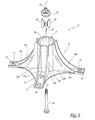
- Each fixing device 2 consists of an element 8 identical to that shown in FIG. 2.
- the body of each element 8 is in the form of a vertical cylinder 8 a whose concave face 9 is of geometry complementary to the outer surface of the tubular end 3 of the post.
- each element 8 On the outside of the cylinder 8 , each element 8 has four legs 10. These extend from the lower end of the cylinder 8 a towards the outside of the element 8 in two directions D1D1 'and D2D2' generally orthogonal to the longitudinal axis CC 'of the cylinder 8 a . These directions D1D1 'and D2D2' are also perpendicular to each other.
- Each tab 10 has a generally rectangular shape. At the most distant end of the cylinder 8 a , each tab 10 is provided with oblong holes 11, aligned longitudinally and allowing the passage of a fixing means, for example a bolt 11 a , intended to connect the tab 10 to the supporting structure 1.
- Each leg 10 comprises, from this end carrying the fixing means 11, two parallel vertical reinforcing ribs 12 a extending in an arc of a circle in the direction of the upper end of the vertical cylinder 8 a on the entire length of it.
- a horizontal rib 12 b similar in shape to the ribs 12 a , extends horizontally between two legs 10 of an element 8 and connects the latter between them and at the lower end of the cylinder.
- These ribs 12 a , 12 b are fixed on the two long sides of each leg 10.
- These legs 10 are made of an easily sawn material so as to be able to adapt the length of the legs 10, and therefore the number of bolts 11 a , to the different load-bearing configurations and / or surfaces 1 encountered. This material is based on aluminum to avoid the risk of corrosion after adaptation of the element 8 to its installation area.
- the base 8 b of the cylinder 8 a from which the legs 10 extend, is provided with a recess 13, in the form of a funnel, formed on the external face of the base 8 b .
- This recess 13 is provided with a central orifice 14.
- This orifice extends inside an element 15 and opens out inside the cylinder 8 a .
- This element 15 comprises a central part, the external surface 15 b of which is frustoconical, and three star branches 15 c .
- the wall of the cylinder 8 has a variable thickness.
- the thicker part of this wall is located at the base of the cylinder 8a and the thinnest portion at the open terminal end of the latter.
- the internal face 9 of the cylinder 8 has an angle with the longitudinal axis CC 'of the housing 9 a and diverges in the direction of its outlet.
- the frustoconical element 15 is provided, at its periphery, of several tabs 16. These tabs 16 are shaped of trapezoid rectangle and are fixed, by their small base on the external wall of element 15. They extend thus along the wall of the element 15 according to radial directions with respect to the axis CC '. These tabs 16 extend beyond the free end of the element 15 into which opens the orifice 14. These tabs are evenly spaced, in pairs, on the outer wall of item 15.
- the element 15 and the tongues 16 thus form part of the means for blocking the end 3 of the post.
- These means also include a wedge 17 in the form of a truncated cone. This corner 17 is arranged so that its small base 17 a is opposite the small base 15a of the element 15.
- Plane fins 20, full and generally in the shape of a trapezoid, are positioned vertically between the element 15 and the corner 17. These fins are arranged by making their two inclined sides 20 a , 20 b respectively coincide with the external surfaces 15 b respectively and 17 b of the parts 15 and 17. In this position, the fins 20 have their large bases 20c directed towards the inner face 9 of the housing 9 a.
- the tubular end 3 of a post When the tubular end 3 of a post is introduced into the housing 9 a , this end, depending on its diameter and / or the thickness of its wall, penetrates more or less inside the cylinder 8 a . In fact, the inclination of the internal face 9 of the housing 9 a can form a stop for the translational movement of the tubular end 3 in the direction of the base 8 b of the cylinder. The end 3 can also rest on the base 8 b .
- the walls of the latter are positioned between the internal face 9 of the cylinder 8 a and the large bases 20 c of the fins 20.
- the rod When, from the recess 13, the rod is screwed threaded 18, it drives in translation the wedge 17 thanks to the blocking in rotation by the bolt 19 of the rod threaded 18 in the corner 17.
- the corner 17 causes a closure of the angular sector defined by the surfaces 15 b and 17 b of these two parts.
- This movement causes a displacement (arrow F) of the fins 20 by respective sliding of the walls 15 b and 17 b on the walls 20 a and 20 b of the fins.
- the large bases 20 c of the fins 20 are supported on the internal wall 3 a of the tubular end 3 of the post.
- the tongues 16 make it possible to hold the fins 20 in a generally vertical position and guide them during this movement.
- a fixing device comprising at least three fins 20, regularly arranged around the element 15, allows uniform support and effective blocking of the tubular end 3 of the various posts encountered.
- the threaded rod 18 ensures the locking in position of the end of the post in the cylinder 8 a . It suffices, in a second step, to fix the assembly to the carrying surface 1 by the lugs 10 and the bolts 11 a .
- the fixing device according to the invention is advantageously made of light parts resistant to corrosion, for example in cast aluminum.
- the tubular end 3 has a section other than circular, the shape of element 8 being then adapted as well as the form, the arrangement and the number of fins 20.
- the fins 20 can be held in place by grooves and / or tongues arranged on the wall 17b of the corner 17.
- the fins can be held by a holding member such as an O-ring passing through a groove formed in the large base 20 c of each fin.
- the shape and number of the horizontal ribs 12 b and / or vertical 12 a may also be different.
- the element tubular 8 consists of two half-elements, preferably essentially identical in the form of a half-cylinder.
- each of the vertical edges of a half cylinder for example carries knuckles regularly spaced and staggered relative to the knuckles of the other half cylinder.
Landscapes
- Engineering & Computer Science (AREA)
- Architecture (AREA)
- Health & Medical Sciences (AREA)
- General Health & Medical Sciences (AREA)
- Business, Economics & Management (AREA)
- Emergency Management (AREA)
- Civil Engineering (AREA)
- Structural Engineering (AREA)
- Joining Of Building Structures In Genera (AREA)
- Mutual Connection Of Rods And Tubes (AREA)
- Road Signs Or Road Markings (AREA)
- Emergency Lowering Means (AREA)
- Holders For Apparel And Elements Relating To Apparel (AREA)
- Regulating Braking Force (AREA)
- Pinball Game Machines (AREA)
- Fittings On The Vehicle Exterior For Carrying Loads, And Devices For Holding Or Mounting Articles (AREA)
- Basic Packing Technique (AREA)
Applications Claiming Priority (2)
| Application Number | Priority Date | Filing Date | Title |
|---|---|---|---|
| FR0216659 | 2002-12-24 | ||
| FR0216659A FR2849120B1 (fr) | 2002-12-24 | 2002-12-24 | Dispositif de fixation d'un potelet d'arrimage a une surface porteuse |
Publications (2)
| Publication Number | Publication Date |
|---|---|
| EP1433501A1 true EP1433501A1 (de) | 2004-06-30 |
| EP1433501B1 EP1433501B1 (de) | 2005-07-13 |
Family
ID=32406508
Family Applications (1)
| Application Number | Title | Priority Date | Filing Date |
|---|---|---|---|
| EP03356210A Expired - Lifetime EP1433501B1 (de) | 2002-12-24 | 2003-12-23 | Vorrichtung zur Befestigung eines Ankerpfostens an einer Tragstruktur |
Country Status (5)
| Country | Link |
|---|---|
| EP (1) | EP1433501B1 (de) |
| AT (1) | ATE299389T1 (de) |
| DE (1) | DE60301011T2 (de) |
| ES (1) | ES2242152T3 (de) |
| FR (1) | FR2849120B1 (de) |
Cited By (1)
| Publication number | Priority date | Publication date | Assignee | Title |
|---|---|---|---|---|
| EP4218946A1 (de) * | 2022-01-28 | 2023-08-02 | APP Dachgarten GmbH | Stützenfuss einer seilhaltevorrichtung |
Families Citing this family (1)
| Publication number | Priority date | Publication date | Assignee | Title |
|---|---|---|---|---|
| US9803330B2 (en) * | 2015-10-07 | 2017-10-31 | Timothy Seay | Post support and post support system |
Citations (7)
| Publication number | Priority date | Publication date | Assignee | Title |
|---|---|---|---|---|
| US2784015A (en) * | 1953-04-24 | 1957-03-05 | Carl G Swanson | Pole base |
| US3841695A (en) * | 1971-12-21 | 1974-10-15 | E Woodward | Stake pocket adapter |
| US4045003A (en) * | 1973-03-14 | 1977-08-30 | Mccluskey John R | Support devices for stanchions |
| DE8535843U1 (de) * | 1985-12-20 | 1986-03-06 | Junker, Wilhelm, 7150 Backnang | Pfosten für Verkehrszeichen und Verkehrseinrichtungen |
| EP0641891A1 (de) * | 1993-09-03 | 1995-03-08 | Ateliers Reunis Caddie S.A. | Fassungsbuchse für rohrförmigen, zylindrischen Pfosten |
| EP0697486A1 (de) * | 1994-08-04 | 1996-02-21 | Helmut Heienbrock | Uni-Einsteckhülse |
| US5632464A (en) * | 1995-09-05 | 1997-05-27 | Aberle; Steven C. | Ground pocket support |
-
2002
- 2002-12-24 FR FR0216659A patent/FR2849120B1/fr not_active Expired - Fee Related
-
2003
- 2003-12-23 AT AT03356210T patent/ATE299389T1/de not_active IP Right Cessation
- 2003-12-23 ES ES03356210T patent/ES2242152T3/es not_active Expired - Lifetime
- 2003-12-23 DE DE60301011T patent/DE60301011T2/de not_active Expired - Lifetime
- 2003-12-23 EP EP03356210A patent/EP1433501B1/de not_active Expired - Lifetime
Patent Citations (7)
| Publication number | Priority date | Publication date | Assignee | Title |
|---|---|---|---|---|
| US2784015A (en) * | 1953-04-24 | 1957-03-05 | Carl G Swanson | Pole base |
| US3841695A (en) * | 1971-12-21 | 1974-10-15 | E Woodward | Stake pocket adapter |
| US4045003A (en) * | 1973-03-14 | 1977-08-30 | Mccluskey John R | Support devices for stanchions |
| DE8535843U1 (de) * | 1985-12-20 | 1986-03-06 | Junker, Wilhelm, 7150 Backnang | Pfosten für Verkehrszeichen und Verkehrseinrichtungen |
| EP0641891A1 (de) * | 1993-09-03 | 1995-03-08 | Ateliers Reunis Caddie S.A. | Fassungsbuchse für rohrförmigen, zylindrischen Pfosten |
| EP0697486A1 (de) * | 1994-08-04 | 1996-02-21 | Helmut Heienbrock | Uni-Einsteckhülse |
| US5632464A (en) * | 1995-09-05 | 1997-05-27 | Aberle; Steven C. | Ground pocket support |
Cited By (1)
| Publication number | Priority date | Publication date | Assignee | Title |
|---|---|---|---|---|
| EP4218946A1 (de) * | 2022-01-28 | 2023-08-02 | APP Dachgarten GmbH | Stützenfuss einer seilhaltevorrichtung |
Also Published As
| Publication number | Publication date |
|---|---|
| DE60301011T2 (de) | 2006-05-24 |
| ES2242152T3 (es) | 2005-11-01 |
| FR2849120B1 (fr) | 2005-09-16 |
| DE60301011D1 (de) | 2005-08-18 |
| ATE299389T1 (de) | 2005-07-15 |
| FR2849120A1 (fr) | 2004-06-25 |
| EP1433501B1 (de) | 2005-07-13 |
Similar Documents
| Publication | Publication Date | Title |
|---|---|---|
| FR2594187A1 (fr) | Raccord en croix pour tubes croises | |
| EP1927707A1 (de) | Sicherheitsvorrichtung an Maschinen zum Heben von Wand- und Deckenplatten | |
| EP3219873A1 (de) | Verteilerkasten zum einbau von kanalisationsrohren, der zur positionierung auf einer armatur geeignet ist | |
| EP1433501B1 (de) | Vorrichtung zur Befestigung eines Ankerpfostens an einer Tragstruktur | |
| EP0839975A1 (de) | Verankerungsvorrichtung | |
| WO2020239667A1 (fr) | Dispositif et procédé d'ancrage d'un équipement à une structure de génie civil | |
| FR2898180A1 (fr) | Dispositif orientable de suspension d'appareillage | |
| FR2724196A1 (fr) | Dispositif de fixation d'un mat en forme de cylindre creux et mat apte a etre installe a l'aide d'un tel dispositif | |
| FR2981962A1 (fr) | Sabot de garde-corps a collerette d'etancheite | |
| FR3001478A1 (fr) | Dispositif d'ancrage | |
| FR2901826A1 (fr) | Bride de fixation d'un panneau de cloture | |
| FR2829777A1 (fr) | Dispositif d'ancrage au sol d'un objet | |
| FR2913998A1 (fr) | Dispositif de maintien de tige exterieur | |
| EP1393777B1 (de) | Strebekopf | |
| FR2791378A1 (fr) | Cloture constituee de panneaux montes entre poteaux et procede d'edification d'une telle cloture | |
| EP4520896B1 (de) | Führungsvorrichtung zur montage eines turmfasses und montageverfahren dafür | |
| FR2820769A1 (fr) | Panneau garde-corps de securite | |
| FR2801331A1 (fr) | Structure de securite pour le travail en toiture | |
| FR3098534A1 (fr) | Ancre de levage pour mur à coffrage intégré et mur à coffrage intégré comportant ladite ancre de levage | |
| FR2824956A1 (fr) | Support d'antennes securise | |
| CH660618A5 (en) | Device for guiding tubes and/or pipes coming out of concrete slabs and its use | |
| FR2623241A1 (fr) | Dispositif d'ancrage d'une echelle sur un angle de poteau | |
| FR3032987A1 (fr) | Potelet de garde-corps de securite et garde-corps de securite equipe de tels potelets | |
| FR3103970A1 (fr) | Dispositif de montage d’un appareilage sur une plateforme surélevée. | |
| EP1619325A2 (de) | Anti-kletter Vorrichtung |
Legal Events
| Date | Code | Title | Description |
|---|---|---|---|
| PUAI | Public reference made under article 153(3) epc to a published international application that has entered the european phase |
Free format text: ORIGINAL CODE: 0009012 |
|
| AK | Designated contracting states |
Kind code of ref document: A1 Designated state(s): AT BE BG CH CY CZ DE DK EE ES FI FR GB GR HU IE IT LI LU MC NL PT RO SE SI SK TR |
|
| AX | Request for extension of the european patent |
Extension state: AL LT LV MK |
|
| 17P | Request for examination filed |
Effective date: 20041008 |
|
| GRAP | Despatch of communication of intention to grant a patent |
Free format text: ORIGINAL CODE: EPIDOSNIGR1 |
|
| AKX | Designation fees paid |
Designated state(s): AT BE BG CH CY CZ DE DK EE ES FI FR GB GR HU IE IT LI LU MC NL PT RO SE SI SK TR |
|
| GRAS | Grant fee paid |
Free format text: ORIGINAL CODE: EPIDOSNIGR3 |
|
| GRAA | (expected) grant |
Free format text: ORIGINAL CODE: 0009210 |
|
| AK | Designated contracting states |
Kind code of ref document: B1 Designated state(s): AT BE BG CH CY CZ DE DK EE ES FI FR GB GR HU IE IT LI LU MC NL PT RO SE SI SK TR |
|
| PG25 | Lapsed in a contracting state [announced via postgrant information from national office to epo] |
Ref country code: IE Free format text: LAPSE BECAUSE OF FAILURE TO SUBMIT A TRANSLATION OF THE DESCRIPTION OR TO PAY THE FEE WITHIN THE PRESCRIBED TIME-LIMIT Effective date: 20050713 Ref country code: NL Free format text: LAPSE BECAUSE OF FAILURE TO SUBMIT A TRANSLATION OF THE DESCRIPTION OR TO PAY THE FEE WITHIN THE PRESCRIBED TIME-LIMIT Effective date: 20050713 Ref country code: AT Free format text: LAPSE BECAUSE OF FAILURE TO SUBMIT A TRANSLATION OF THE DESCRIPTION OR TO PAY THE FEE WITHIN THE PRESCRIBED TIME-LIMIT Effective date: 20050713 Ref country code: FI Free format text: LAPSE BECAUSE OF FAILURE TO SUBMIT A TRANSLATION OF THE DESCRIPTION OR TO PAY THE FEE WITHIN THE PRESCRIBED TIME-LIMIT Effective date: 20050713 Ref country code: RO Free format text: LAPSE BECAUSE OF FAILURE TO SUBMIT A TRANSLATION OF THE DESCRIPTION OR TO PAY THE FEE WITHIN THE PRESCRIBED TIME-LIMIT Effective date: 20050713 Ref country code: SK Free format text: LAPSE BECAUSE OF FAILURE TO SUBMIT A TRANSLATION OF THE DESCRIPTION OR TO PAY THE FEE WITHIN THE PRESCRIBED TIME-LIMIT Effective date: 20050713 Ref country code: TR Free format text: LAPSE BECAUSE OF FAILURE TO SUBMIT A TRANSLATION OF THE DESCRIPTION OR TO PAY THE FEE WITHIN THE PRESCRIBED TIME-LIMIT Effective date: 20050713 Ref country code: EE Free format text: LAPSE BECAUSE OF FAILURE TO SUBMIT A TRANSLATION OF THE DESCRIPTION OR TO PAY THE FEE WITHIN THE PRESCRIBED TIME-LIMIT Effective date: 20050713 Ref country code: CZ Free format text: LAPSE BECAUSE OF FAILURE TO SUBMIT A TRANSLATION OF THE DESCRIPTION OR TO PAY THE FEE WITHIN THE PRESCRIBED TIME-LIMIT Effective date: 20050713 Ref country code: SI Free format text: LAPSE BECAUSE OF FAILURE TO SUBMIT A TRANSLATION OF THE DESCRIPTION OR TO PAY THE FEE WITHIN THE PRESCRIBED TIME-LIMIT Effective date: 20050713 |
|
| REG | Reference to a national code |
Ref country code: GB Ref legal event code: FG4D Free format text: NOT ENGLISH |
|
| REG | Reference to a national code |
Ref country code: CH Ref legal event code: EP |
|
| REG | Reference to a national code |
Ref country code: IE Ref legal event code: FG4D Free format text: LANGUAGE OF EP DOCUMENT: FRENCH |
|
| REF | Corresponds to: |
Ref document number: 60301011 Country of ref document: DE Date of ref document: 20050818 Kind code of ref document: P |
|
| GBT | Gb: translation of ep patent filed (gb section 77(6)(a)/1977) |
Effective date: 20050917 |
|
| PG25 | Lapsed in a contracting state [announced via postgrant information from national office to epo] |
Ref country code: BG Free format text: LAPSE BECAUSE OF FAILURE TO SUBMIT A TRANSLATION OF THE DESCRIPTION OR TO PAY THE FEE WITHIN THE PRESCRIBED TIME-LIMIT Effective date: 20051013 Ref country code: SE Free format text: LAPSE BECAUSE OF FAILURE TO SUBMIT A TRANSLATION OF THE DESCRIPTION OR TO PAY THE FEE WITHIN THE PRESCRIBED TIME-LIMIT Effective date: 20051013 Ref country code: GR Free format text: LAPSE BECAUSE OF FAILURE TO SUBMIT A TRANSLATION OF THE DESCRIPTION OR TO PAY THE FEE WITHIN THE PRESCRIBED TIME-LIMIT Effective date: 20051013 Ref country code: DK Free format text: LAPSE BECAUSE OF FAILURE TO SUBMIT A TRANSLATION OF THE DESCRIPTION OR TO PAY THE FEE WITHIN THE PRESCRIBED TIME-LIMIT Effective date: 20051013 |
|
| REG | Reference to a national code |
Ref country code: ES Ref legal event code: FG2A Ref document number: 2242152 Country of ref document: ES Kind code of ref document: T3 |
|
| PG25 | Lapsed in a contracting state [announced via postgrant information from national office to epo] |
Ref country code: PT Free format text: LAPSE BECAUSE OF FAILURE TO SUBMIT A TRANSLATION OF THE DESCRIPTION OR TO PAY THE FEE WITHIN THE PRESCRIBED TIME-LIMIT Effective date: 20051219 |
|
| PG25 | Lapsed in a contracting state [announced via postgrant information from national office to epo] |
Ref country code: CY Free format text: LAPSE BECAUSE OF FAILURE TO SUBMIT A TRANSLATION OF THE DESCRIPTION OR TO PAY THE FEE WITHIN THE PRESCRIBED TIME-LIMIT Effective date: 20051223 |
|
| NLV1 | Nl: lapsed or annulled due to failure to fulfill the requirements of art. 29p and 29m of the patents act | ||
| PG25 | Lapsed in a contracting state [announced via postgrant information from national office to epo] |
Ref country code: HU Free format text: LAPSE BECAUSE OF FAILURE TO SUBMIT A TRANSLATION OF THE DESCRIPTION OR TO PAY THE FEE WITHIN THE PRESCRIBED TIME-LIMIT Effective date: 20060114 |
|
| REG | Reference to a national code |
Ref country code: IE Ref legal event code: FD4D |
|
| PLBE | No opposition filed within time limit |
Free format text: ORIGINAL CODE: 0009261 |
|
| STAA | Information on the status of an ep patent application or granted ep patent |
Free format text: STATUS: NO OPPOSITION FILED WITHIN TIME LIMIT |
|
| 26N | No opposition filed |
Effective date: 20060418 |
|
| PGFP | Annual fee paid to national office [announced via postgrant information from national office to epo] |
Ref country code: CH Payment date: 20081120 Year of fee payment: 6 Ref country code: LU Payment date: 20081222 Year of fee payment: 6 Ref country code: MC Payment date: 20081121 Year of fee payment: 6 |
|
| PG25 | Lapsed in a contracting state [announced via postgrant information from national office to epo] |
Ref country code: MC Free format text: LAPSE BECAUSE OF NON-PAYMENT OF DUE FEES Effective date: 20100701 |
|
| REG | Reference to a national code |
Ref country code: CH Ref legal event code: PL |
|
| PG25 | Lapsed in a contracting state [announced via postgrant information from national office to epo] |
Ref country code: LI Free format text: LAPSE BECAUSE OF NON-PAYMENT OF DUE FEES Effective date: 20091231 Ref country code: CH Free format text: LAPSE BECAUSE OF NON-PAYMENT OF DUE FEES Effective date: 20091231 |
|
| PGFP | Annual fee paid to national office [announced via postgrant information from national office to epo] |
Ref country code: GB Payment date: 20101123 Year of fee payment: 8 Ref country code: IT Payment date: 20101223 Year of fee payment: 8 |
|
| PG25 | Lapsed in a contracting state [announced via postgrant information from national office to epo] |
Ref country code: LU Free format text: LAPSE BECAUSE OF NON-PAYMENT OF DUE FEES Effective date: 20091223 |
|
| PGFP | Annual fee paid to national office [announced via postgrant information from national office to epo] |
Ref country code: FR Payment date: 20111013 Year of fee payment: 9 Ref country code: ES Payment date: 20111222 Year of fee payment: 9 |
|
| PGFP | Annual fee paid to national office [announced via postgrant information from national office to epo] |
Ref country code: BE Payment date: 20111230 Year of fee payment: 9 |
|
| PGFP | Annual fee paid to national office [announced via postgrant information from national office to epo] |
Ref country code: DE Payment date: 20111212 Year of fee payment: 9 |
|
| BERE | Be: lapsed |
Owner name: GAMESYSTEM Effective date: 20121231 |
|
| GBPC | Gb: european patent ceased through non-payment of renewal fee |
Effective date: 20121223 |
|
| REG | Reference to a national code |
Ref country code: FR Ref legal event code: ST Effective date: 20130830 |
|
| PG25 | Lapsed in a contracting state [announced via postgrant information from national office to epo] |
Ref country code: BE Free format text: LAPSE BECAUSE OF NON-PAYMENT OF DUE FEES Effective date: 20121231 |
|
| REG | Reference to a national code |
Ref country code: DE Ref legal event code: R119 Ref document number: 60301011 Country of ref document: DE Effective date: 20130702 |
|
| PG25 | Lapsed in a contracting state [announced via postgrant information from national office to epo] |
Ref country code: DE Free format text: LAPSE BECAUSE OF NON-PAYMENT OF DUE FEES Effective date: 20130702 |
|
| PG25 | Lapsed in a contracting state [announced via postgrant information from national office to epo] |
Ref country code: GB Free format text: LAPSE BECAUSE OF NON-PAYMENT OF DUE FEES Effective date: 20121223 Ref country code: FR Free format text: LAPSE BECAUSE OF NON-PAYMENT OF DUE FEES Effective date: 20130102 |
|
| PG25 | Lapsed in a contracting state [announced via postgrant information from national office to epo] |
Ref country code: IT Free format text: LAPSE BECAUSE OF NON-PAYMENT OF DUE FEES Effective date: 20121223 |
|
| REG | Reference to a national code |
Ref country code: ES Ref legal event code: FD2A Effective date: 20140306 |
|
| PG25 | Lapsed in a contracting state [announced via postgrant information from national office to epo] |
Ref country code: ES Free format text: LAPSE BECAUSE OF NON-PAYMENT OF DUE FEES Effective date: 20121224 |