EP1433536A1 - Machine a enduire a cartouche - Google Patents
Machine a enduire a cartouche Download PDFInfo
- Publication number
- EP1433536A1 EP1433536A1 EP02755676A EP02755676A EP1433536A1 EP 1433536 A1 EP1433536 A1 EP 1433536A1 EP 02755676 A EP02755676 A EP 02755676A EP 02755676 A EP02755676 A EP 02755676A EP 1433536 A1 EP1433536 A1 EP 1433536A1
- Authority
- EP
- European Patent Office
- Prior art keywords
- cartridge
- paint
- mount portion
- housing
- magnetic
- Prior art date
- Legal status (The legal status is an assumption and is not a legal conclusion. Google has not performed a legal analysis and makes no representation as to the accuracy of the status listed.)
- Withdrawn
Links
Images




Classifications
-
- B—PERFORMING OPERATIONS; TRANSPORTING
- B05—SPRAYING OR ATOMISING IN GENERAL; APPLYING FLUENT MATERIALS TO SURFACES, IN GENERAL
- B05B—SPRAYING APPARATUS; ATOMISING APPARATUS; NOZZLES
- B05B3/00—Spraying or sprinkling apparatus with moving outlet elements or moving deflecting elements
- B05B3/02—Spraying or sprinkling apparatus with moving outlet elements or moving deflecting elements with rotating elements
- B05B3/10—Spraying or sprinkling apparatus with moving outlet elements or moving deflecting elements with rotating elements discharging over substantially the whole periphery of the rotating member
- B05B3/1064—Spraying or sprinkling apparatus with moving outlet elements or moving deflecting elements with rotating elements discharging over substantially the whole periphery of the rotating member the liquid or other fluent material to be sprayed being axially supplied to the rotating member through a hollow rotating shaft
-
- B—PERFORMING OPERATIONS; TRANSPORTING
- B05—SPRAYING OR ATOMISING IN GENERAL; APPLYING FLUENT MATERIALS TO SURFACES, IN GENERAL
- B05B—SPRAYING APPARATUS; ATOMISING APPARATUS; NOZZLES
- B05B12/00—Arrangements for controlling delivery; Arrangements for controlling the spray area
- B05B12/14—Arrangements for controlling delivery; Arrangements for controlling the spray area for supplying a selected one of a plurality of liquids or other fluent materials or several in selected proportions to a spray apparatus, e.g. to a single spray outlet
-
- B—PERFORMING OPERATIONS; TRANSPORTING
- B05—SPRAYING OR ATOMISING IN GENERAL; APPLYING FLUENT MATERIALS TO SURFACES, IN GENERAL
- B05B—SPRAYING APPARATUS; ATOMISING APPARATUS; NOZZLES
- B05B12/00—Arrangements for controlling delivery; Arrangements for controlling the spray area
- B05B12/14—Arrangements for controlling delivery; Arrangements for controlling the spray area for supplying a selected one of a plurality of liquids or other fluent materials or several in selected proportions to a spray apparatus, e.g. to a single spray outlet
- B05B12/1463—Arrangements for controlling delivery; Arrangements for controlling the spray area for supplying a selected one of a plurality of liquids or other fluent materials or several in selected proportions to a spray apparatus, e.g. to a single spray outlet separate containers for different materials to be sprayed being moved from a first location, e.g. a filling station, where they are fluidically disconnected from the spraying apparatus, to a second location, generally close to the spraying apparatus, where they are fluidically connected to the latter
-
- B—PERFORMING OPERATIONS; TRANSPORTING
- B05—SPRAYING OR ATOMISING IN GENERAL; APPLYING FLUENT MATERIALS TO SURFACES, IN GENERAL
- B05B—SPRAYING APPARATUS; ATOMISING APPARATUS; NOZZLES
- B05B5/00—Electrostatic spraying apparatus; Spraying apparatus with means for charging the spray electrically; Apparatus for spraying liquids or other fluent materials by other electric means
- B05B5/025—Discharge apparatus, e.g. electrostatic spray guns
- B05B5/04—Discharge apparatus, e.g. electrostatic spray guns characterised by having rotary outlet or deflecting elements, i.e. spraying being also effected by centrifugal forces
-
- B—PERFORMING OPERATIONS; TRANSPORTING
- B05—SPRAYING OR ATOMISING IN GENERAL; APPLYING FLUENT MATERIALS TO SURFACES, IN GENERAL
- B05B—SPRAYING APPARATUS; ATOMISING APPARATUS; NOZZLES
- B05B5/00—Electrostatic spraying apparatus; Spraying apparatus with means for charging the spray electrically; Apparatus for spraying liquids or other fluent materials by other electric means
- B05B5/16—Arrangements for supplying liquids or other fluent material
-
- B—PERFORMING OPERATIONS; TRANSPORTING
- B05—SPRAYING OR ATOMISING IN GENERAL; APPLYING FLUENT MATERIALS TO SURFACES, IN GENERAL
- B05B—SPRAYING APPARATUS; ATOMISING APPARATUS; NOZZLES
- B05B5/00—Electrostatic spraying apparatus; Spraying apparatus with means for charging the spray electrically; Apparatus for spraying liquids or other fluent materials by other electric means
- B05B5/16—Arrangements for supplying liquids or other fluent material
- B05B5/1608—Arrangements for supplying liquids or other fluent material the liquid or other fluent material being electrically conductive
-
- B—PERFORMING OPERATIONS; TRANSPORTING
- B05—SPRAYING OR ATOMISING IN GENERAL; APPLYING FLUENT MATERIALS TO SURFACES, IN GENERAL
- B05B—SPRAYING APPARATUS; ATOMISING APPARATUS; NOZZLES
- B05B5/00—Electrostatic spraying apparatus; Spraying apparatus with means for charging the spray electrically; Apparatus for spraying liquids or other fluent materials by other electric means
- B05B5/16—Arrangements for supplying liquids or other fluent material
- B05B5/1608—Arrangements for supplying liquids or other fluent material the liquid or other fluent material being electrically conductive
- B05B5/1675—Arrangements for supplying liquids or other fluent material the liquid or other fluent material being electrically conductive the supply means comprising a piston, e.g. a piston pump
-
- B—PERFORMING OPERATIONS; TRANSPORTING
- B05—SPRAYING OR ATOMISING IN GENERAL; APPLYING FLUENT MATERIALS TO SURFACES, IN GENERAL
- B05B—SPRAYING APPARATUS; ATOMISING APPARATUS; NOZZLES
- B05B5/00—Electrostatic spraying apparatus; Spraying apparatus with means for charging the spray electrically; Apparatus for spraying liquids or other fluent materials by other electric means
- B05B5/16—Arrangements for supplying liquids or other fluent material
- B05B5/1691—Apparatus to be carried on or by a person or with a container fixed to the discharge device
-
- B—PERFORMING OPERATIONS; TRANSPORTING
- B05—SPRAYING OR ATOMISING IN GENERAL; APPLYING FLUENT MATERIALS TO SURFACES, IN GENERAL
- B05B—SPRAYING APPARATUS; ATOMISING APPARATUS; NOZZLES
- B05B12/00—Arrangements for controlling delivery; Arrangements for controlling the spray area
- B05B12/14—Arrangements for controlling delivery; Arrangements for controlling the spray area for supplying a selected one of a plurality of liquids or other fluent materials or several in selected proportions to a spray apparatus, e.g. to a single spray outlet
- B05B12/1454—Arrangements for controlling delivery; Arrangements for controlling the spray area for supplying a selected one of a plurality of liquids or other fluent materials or several in selected proportions to a spray apparatus, e.g. to a single spray outlet separate units comprising both a material container and a spray device permanently connected thereto being removably attached to a part of the spray apparatus, e.g. to a robot arm
-
- B—PERFORMING OPERATIONS; TRANSPORTING
- B05—SPRAYING OR ATOMISING IN GENERAL; APPLYING FLUENT MATERIALS TO SURFACES, IN GENERAL
- B05B—SPRAYING APPARATUS; ATOMISING APPARATUS; NOZZLES
- B05B12/00—Arrangements for controlling delivery; Arrangements for controlling the spray area
- B05B12/14—Arrangements for controlling delivery; Arrangements for controlling the spray area for supplying a selected one of a plurality of liquids or other fluent materials or several in selected proportions to a spray apparatus, e.g. to a single spray outlet
- B05B12/1472—Arrangements for controlling delivery; Arrangements for controlling the spray area for supplying a selected one of a plurality of liquids or other fluent materials or several in selected proportions to a spray apparatus, e.g. to a single spray outlet separate supply lines supplying different materials to separate outlets of the spraying apparatus
-
- B—PERFORMING OPERATIONS; TRANSPORTING
- B05—SPRAYING OR ATOMISING IN GENERAL; APPLYING FLUENT MATERIALS TO SURFACES, IN GENERAL
- B05B—SPRAYING APPARATUS; ATOMISING APPARATUS; NOZZLES
- B05B3/00—Spraying or sprinkling apparatus with moving outlet elements or moving deflecting elements
- B05B3/02—Spraying or sprinkling apparatus with moving outlet elements or moving deflecting elements with rotating elements
- B05B3/10—Spraying or sprinkling apparatus with moving outlet elements or moving deflecting elements with rotating elements discharging over substantially the whole periphery of the rotating member
- B05B3/1092—Means for supplying shaping gas
-
- B—PERFORMING OPERATIONS; TRANSPORTING
- B05—SPRAYING OR ATOMISING IN GENERAL; APPLYING FLUENT MATERIALS TO SURFACES, IN GENERAL
- B05B—SPRAYING APPARATUS; ATOMISING APPARATUS; NOZZLES
- B05B5/00—Electrostatic spraying apparatus; Spraying apparatus with means for charging the spray electrically; Apparatus for spraying liquids or other fluent materials by other electric means
- B05B5/025—Discharge apparatus, e.g. electrostatic spray guns
- B05B5/04—Discharge apparatus, e.g. electrostatic spray guns characterised by having rotary outlet or deflecting elements, i.e. spraying being also effected by centrifugal forces
- B05B5/0403—Discharge apparatus, e.g. electrostatic spray guns characterised by having rotary outlet or deflecting elements, i.e. spraying being also effected by centrifugal forces characterised by the rotating member
- B05B5/0407—Discharge apparatus, e.g. electrostatic spray guns characterised by having rotary outlet or deflecting elements, i.e. spraying being also effected by centrifugal forces characterised by the rotating member with a spraying edge, e.g. like a cup or a bell
-
- B—PERFORMING OPERATIONS; TRANSPORTING
- B05—SPRAYING OR ATOMISING IN GENERAL; APPLYING FLUENT MATERIALS TO SURFACES, IN GENERAL
- B05B—SPRAYING APPARATUS; ATOMISING APPARATUS; NOZZLES
- B05B5/00—Electrostatic spraying apparatus; Spraying apparatus with means for charging the spray electrically; Apparatus for spraying liquids or other fluent materials by other electric means
- B05B5/025—Discharge apparatus, e.g. electrostatic spray guns
- B05B5/04—Discharge apparatus, e.g. electrostatic spray guns characterised by having rotary outlet or deflecting elements, i.e. spraying being also effected by centrifugal forces
- B05B5/0426—Means for supplying shaping gas
Definitions
- This invention relates to a cartridge type coating machine, employing a plural number of paint cartridges of different colors which are adapted to be interchangeably and replaceably set in position on the machine to permit color changes during a coating operation.
- various types of coating machines have been and are resorted to for coating work pieces such as vehicle bodies or the like, including rotary atomizing head type coating machines, hydraulic atomization type coating machines and pneumatic atomization type coating machines.
- rotary atomizing head type coating machines various types of coating machines have been and are resorted to for coating work pieces such as vehicle bodies or the like, including rotary atomizing head type coating machines, hydraulic atomization type coating machines and pneumatic atomization type coating machines.
- a coating machine which can reduce the amounts of paint and solvent to be discarded or consumed at the time of changing the paint color and which can cope with a large number of paint colors.
- cartridge type coating machines e.g., as disclosed in Japanese Patent Laid-Open No. H11-262699 and Japanese Patent Laid-Open No. H8-229446.
- this cartridge type coating machine arrangements are made to replaceably mount paint cartridges, which are filled with different colors, on a housing of the coating machine.
- the machine includes a housing which is provided with a sprayer mount portion and a cartridge mount portion in its front and rear end portions, respectively, a rotary atomizing head type or hydraulic atomization type sprayer unit which is mounted on the sprayer mount portion of the housing to spray supplied paint toward a work piece, and paint cartridges which are filled with different paint colors and adapted to be replaceably mounted on the cartridge mount portion of the housing.
- the paint cartridges are each constituted largely by a cylindrical container which is closed at the opposite ends and internally filled with paint, and a feed tube which is extended out axially from the container to spurt out paint in the cartridge container therethrough. Further, the cartridge mount portion of the housing is formed in the shape of a bottomed cavity which is open on the rear side. A paint cartridge is set on the cartridge mount portion by fitting engagement therewith of the cartridge container.
- a vacuum space is defined in the cartridge mount portion by an O-ring which is provided around the outer periphery of the cartridge container and brought into sliding contact with inner peripheral surfaces of the cartridge mount portion. Air in the vacuum space is sucked out through a suction passage to hold the paint cartridge fixedly on the cartridge mount portion by suction grip.
- paint cartridges of different colors are selectively mounted on the cartridge mount portion during a coating operation.
- the paint in the cartridge container is spurted out toward the sprayer unit through the feed tube and then sprayed toward a work piece by the sprayer unit.
- the paint cartridge on the coating machine is simply replaced by a cartridge of a next color at the time of changing the paint color, that is to say, the paint color can be changed without entailing wasteful paint discarding or solvent consumption.
- an O-ring which is provided around the outer periphery of the cartridge container is brought into sliding contact with inner peripheral surfaces of the cartridge mount portion to define a vacuum space therebetween.
- the paint cartridge is fixed on the cartridge mount portion by suction force which is produced by sucking air out of the vacuum space.
- the O-ring which is attached to the paint cartridge is simply held in sliding contact with the inner periphery of the cartridge mount portion, it is difficult to seal up the vacuum space completely by the O-ring. Therefore, it is inevitable that atmospheric air incessantly creeps into the vacuum space. This means that, in order to maintain the suction grip on the paint cartridge, a vacuum generator has to be constantly kept in operation to suck out air continuously from the vacuum space.
- the O-ring is brought into frictional contact with inner peripheral surfaces of the cartridge mount portion. Therefore, the O-ring which is repeatedly twisted by frictional contact is susceptible to damages and generally requires replacements at a higher frequency.
- a cartridge type coating machine which can hold a paint cartridge in a cartridge mount portion fixedly in a secure state without applying an external force, for example, without applying a suction force by the use of a vacuum generator or the like, permitting to improve productivity and reliability of the machine while cutting its running cost.
- a cartridge type coating machine which includes a housing with a sprayer unit mount portion and a cartridge mount portion respectively on front and rear sides thereof, a sprayer unit mounted on the sprayer unit mount portion of the housing to spray supplied paint toward a work piece, and a paint cartridge adapted to be replaceably set in the cartridge mount portion of the housing and filled with paint for supply to the sprayer unit.
- the cartridge type coating machine is characterized by the provision of a magnetic holding mechanism provided between the cartridge mount portion of the housing and the paint cartridge to releasably and fixedly hold the paint cartridge in the cartridge mount portion of the housing by magnetic force.
- a paint cartridge as a paint cartridge is mounted on the cartridge mount portion of the housing, it can be securely fixed to the cartridge mount portion by magnetic force of a permanent magnet or electromagnet without applying an external force, for example, by the use of a vacuum generator or the like.
- the magnetic holding mechanism is constituted by permanent magnets attached to one of the cartridge mount portion of the housing and the paint cartridge and magnetic members attached to the other one of the cartridge mount portion and the paint cartridge.
- the magnetic member which is attached to the paint cartridge for example, is attracted to the permanent magnet on the side of the cartridge mount portion and as a result the paint cartridge is securely and fixedly held in the latter by the magnetic holding mechanism.
- the magnetic holding mechanism is constituted by a first permanent magnet attached to one of the cartridge mount portion of the housing and the paint cartridge, and a second permanent magnet attached to the other one of the cartridge mount portion and the paint cartridge in such a way as to confront the first permanent magnet through opposite magnetic poles.
- the second permanent magnet which is attached on the paint cartridge for example, is attracted to the first permanent magnet which is attached on the side of the cartridge mount portion, and as a result the paint cartridge is securely and fixedly held in the latter by the magnetic holding mechanism.
- the magnetic holding mechanism is constituted by a first magnet group consisting of a plural number of permanent magnets and attached to one of the cartridge mount portion of the housing and the paint cartridge, the permanent magnets of the first magnet group being arranged in a row and alternately reversed in magnetic pole position, and a second magnet group consisting of a plural number of permanent magnets and attached to the other one of the cartridge mount portion of the housing and the paint cartridge, the permanent magnets of the second magnet group being arranged into a row in confronting relation with the first magnet group and reversed in magnetic pole position relative to said first magnet group.
- the first and second magnet groups are attracted toward each other, and as a result the paint cartridge is securely fixed in the cartridge mount portion. Further, when the first and second magnet groups come closer to each other, homopolar repulsions and heteropolar attractions take place between permanent magnets of the first and second magnet groups. Therefore, at the time of mounting the paint cartridge on the housing, positional deviations between the cartridge mount portion and the paint cartridge, if any, can be corrected by the repulsive and attracting actions of the permanent magnets.
- an ejection air supply passage is provided in the housing for supplying ejection air between the cartridge mount portion and the paint cartridge at the time of dismantling the latter from the cartridge mount portion of the housing.
- ejection air is supplied to a space between the cartridge mount portion and the paint cartridge through the ejection air supply passage.
- the paint cartridge is pushed outward by ejection air and can be easily dismantled or removed from the cartridge mount portion of the housing against the magnetic force of the magnetic holding mechanism.
- the cartridge mount portion of the housing is formed in the shape of a bottomed cylindrical cavity
- the paint cartridge is provided with a cylindrical container filled with paint and a feed tube extended axially forward from a front end of the container
- the coating machine further comprises a seal member provided either on a bottom surface of the cartridge mount portion or on a front surface of the container, the seal member being brought into abutting engagement with either the front surface of the paint cartridge or the bottom surface of the cartridge mount portion to form an ejection air space therebetween when the paint cartridge is set in the cartridge mount portion of the housing.
- an ejection air space is formed and defined between the cartridge mount portion and the paint cartridge by the seal member. Therefore, upon supplying air to the ejection air space, the air pressure can be efficiently acted on the container of the paint cartridge, permitting to dismantle the paint cartridge extremely in a facilitated manner.
- the seal member is simply abutted against a bottom surface of the cartridge mount portion or a front surface of the cartridge container, so that there is little possibility of the seal member being subjected to twisted deformation or sliding abrasion at the time of loading or unloading a paint cartridge to or from the coating machine.
- a projection and a recess of complementary shapes are provided on confronting surfaces of the above-mentioned permanent magnet and the opposing magnetic member for fitting engagement with each other.
- a projection and a recess of complementary shapes are preferably provided on confronting surfaces of the above-mentioned first and second permanent magnets for fitting engagement with each other.
- the magnetic holding mechanism is constituted by an electromagnet provided on one of the cartridge mount portion of the housing and the paint cartridge, and a magnetic member provided on the other one of the cartridge mount portion and the paint cartridge.
- the electromagnet which is provided, for example, on the side of the cartridge mount portion.
- the magnetic member on the side of the paint cartridge is attracted by the electromagnet, and as a result the paint cartridge is securely fixed in the cartridge mount portion of the machine housing.
- cartridge type coating machine according to the present invention is described more particularly with reference to the accompanying drawings, by way of its preferred embodiments which are each in the form of a rotary atomizing head type coating machine.
- a cartridge type coating machine (hereinafter simply referred to as "coating machine 1" for brevity) which is provided on a coating robot or a reciprocator (not shown), for example.
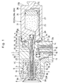
- the coating machine 1 is largely constituted by a housing 2, feed tube passage holes 5 and 10, sprayer unit 6, and paint cartridges 20.
- the housing 2 of the coating machine 1 is formed of an engineering plastics material, for example, such as PTFE, PEEK, PEI, POM, PI, PET and so forth.
- the housing 2 is constituted by a neck portion 2A to be detachably attached, for example, on a wrist portion (not shown) of a coating robot, and a head portion 2B which is formed integrally at the fore end of the neck portion 2A.
- a sprayer unit mount portion 3 in the form of a cylindrical cavity is provided on the front side of the head portion 2B of the housing 2, and a cartridge mount portion 4 similarly in the form of a cylindrical cavity is provided on the rear side of the head portion 2B.
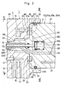
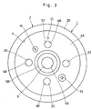
- the cartridge mount portion 4 is in the form of a bottomed blind hole which is open only on the rear side, and, as shown particularly in Figs. 2 and 3, provided with a plural number of magnet fitting grooves 4B, for example, four magnet fitting grooves 4B on its bottom surface 4A at angularly spaced positions in the circumferential direction for mounting permanent magnets 33, which will be described hereinafter.
- a feed tube passage hole which is provided on the side of the housing 2 to extend between and in communication with the sprayer unit mount portion 3 and the cartridge mount portion 4.
- This feed tube passage hole 5 on the side of the housing is composed of a front feed tube passage portion 5A of a small diameter, and a rear conically converging portion 5B which diameter is gradually reduced in a conical shape toward the front feed tube passage portion 5A.
- the feed tube passage portion 5A is formed in coaxial relation with a feed tube passage hole 10 on the side of the sprayer unit, which will be described hereinafter.
- the conically converging portion 5B is held in abutting engagement with a conical projection 22 of the paint cartridge 20, which will be described hereinafter, to hold the latter in position in radial and axial directions.
- the sprayer unit 6 is a sprayer unit for spraying paint toward a work piece.
- the sprayer unit 6 is mounted in the sprayer unit mount portion 3 on the head portion 2B of the housing.
- the sprayer unit 6 is largely constituted by an air motor 7 with a motor case 7A, rotational shaft 7B, air turbine 7C and air bearing 7D, a rotary atomizing head 8 which is put in rotation by the air motor 7 for atomizing paint into finely divided particles by centrifugal atomization and spraying same toward a work piece, and a shaping air ring 9 which is located at the front end of the air motor 7 and provided with a multitude of shaping air outlet holes 9A (only two of which are shown in the drawings).
- feed tube passage hole 10 which is provided on the side of the sprayer unit 6.
- This feed tube passage hole 10 is extended axially through the rotational shaft 7B of the air motor 7.
- the base end of the feed tube passage hole 10 on the side of the sprayer unit is opened into the feed tube passage portion 5A of the feed tube passage hole 5 on the side of the housing, while its fore end is opened into the rotary atomizing head 8.
- the feed tube passage hole 10 on the side of the sprayer unit is formed in coaxial relation with the afore-mentioned feed tube passage portion 5A.
- the feed tube 23 of the paint cartridge 20 is extractably fitted into these feed tube passage holes 5 and 10.
- Designated at 11 is a high voltage generator which is provided in the neck portion 2A of the housing 2.
- the high voltage generator 11 is constituted, for example, by a Cockcroft circuit which is adapted to elevate a source voltage from a power supply (not shown) to a high voltage, for example, to a level between -60 kv and -120 kv.
- the output side of the high voltage generator 11 is electrically connected, for example, to the air motor 7. A high voltage is therefore applied to the rotary atomizing head 8 from the high voltage generator 11 through the rotational shaft 7B of the air motor 7 to charge the paint directly.
- the air passages 12 includes a turbine air passage which supplies turbine air for controlling the air motor 7, a bearing air passage, a brake air passage and a shaping air passage which supplies shaping air for shaping the paint spray pattern.
- a turbine air passage which supplies turbine air for controlling the air motor 7
- a bearing air passage which supplies turbine air for controlling the air motor 7
- a bearing air passage which supplies bearing air for controlling the air motor 7
- a brake air passage which supplies shaping air for shaping the paint spray pattern.
- only one air passage is shown to represent the various air passages as mentioned above.
- extruding thinner passage which is provided on the side of the housing 2.
- extruding thinner supply unit (not shown) which supplies extruding thinner toward the paint cartridge 20.
- the other end of the extruding thinner passage 13 is opened into a female coupling portion (not shown) which is provided on the bottom surface 4A of the cartridge mount portion 4, for communication with an extruding thinner passage 27 on the side of the paint cartridge, which will be described hereinafter.
- pilot air passage 14 which is provided on the side of the housing 2.
- One end of this pilot air passage 14 is connected to a paint valve pilot air source (not shown) through pilot air piping.
- the other end of the pilot air passage 14 is opened into a male coupling portion (not shown) which is provided on the bottom surface 4A of the cartridge mount portion 4, for communication with a pilot air passage 30 on the side of the paint cartridge, which will be described hereinafter.
- Denoted at 15 is an ejection air supply passage which is provided in the housing 2 and opened in the bottom surface 4A of the cartridge mount portion 4.
- This ejection air supply passage 15 is connected to an ejection air source through air piping (both of which are not shown in the drawings).
- ejection air is supplied to an ejection air space 16 (shown in Fig. 2) which is defined between the cartridge mount portion 4 and the container 21 of the paint cartridge 20, permitting to dismantle the latter from the cartridge mount portion 4.
- Indicated at 17 is a thinner valve which is provided in the head portion 2B of the housing 2.
- the thinner valve 17 is accommodated in a thinner valve receptacle cavity 18. Normally, the extruding thinner passage 13 on the side of the housing is blocked by the thinner valve 17 to stop thinner supply to the extruding thinner chamber 26 of the paint cartridge 20.
- pilot air is supplied to the thinner valve 17 from the thinner valve pilot air source (not shown) through the pilot air passage 19, the thinner valve puts the extruding thinner passage 13 into communication to permit thinner supply to the extruding thinner chamber 26.
- paint cartridges 20 which are filled with different colors, color a , color b , .color n , (hereinafter generally referred to as "paint cartridges 20") for supply to the rotary atomizing head 8. Further, as shown in Fig. 4, the paint cartridges 20 are each largely constituted by a container 21 and a feed tube 23.
- the container 21 is a container which constitutes a main body of the paint cartridge 20.
- the container 21 is formed in the shape of a cylindrical shell (cylinder) of a diameter slightly smaller than the inside diameter of the cartridge mount portion 4 of the housing. Front and rear ends of the container 21 are closed with front and rear surfaces 21A and 21B, respectively. As shown in Fig. 5, a plural number of magnetic member fitting grooves 21C are formed in the front surface 21A of the container 21, for example, at four angularly spaced positions in the circumferential direction, to attach thereto magnetic members 34, which will be described hereinafter.
- annular groove 21D is formed around the outer periphery of the container 21 to receive therein an O-ring 31, which will be described hereinafter.
- knob portion 21E is formed on the rear surface 21B to be gripped by a gripper at the time of replacement of the paint cartridge 20.
- Designated at 22 is a conical projection which is projected axially forward from and at a center position of the front surface 21A.
- the conical projection 22 which forms part of the container 21 is gradually reduced in diameter in the forward direction.
- the conical projection 22 is brought into fitting engagement with the conically converging portion 5B of the feed tube passage hole 5 thereby to set the container 21 in position in the axial and radial directions.
- a feed tube which is extended axially forward from a distal end of the conical projection 22 of the cartridge container 21.
- a paint passage 23A is formed coaxially through the feed tube 23.
- the base end of the paint passage 23A is connected to a paint chamber 25, which will be described hereinafter, while its fore end is opened toward the rotary atomizing head 8.
- the feed tube 23 is passed into the feed tube passage holes 5 and 10 and its fore end is placed within the rotary atomizing head 8.
- the feed tube 23 serves to receive a supply of paint from the paint chamber 25, which will be described hereinafter, and convey same through the paint passage 23A, letting the paints spurt from the fore end of the paint passage 23A toward the rotary atomizing head 8. Besides, at the time of replenishing paint into the paint chamber 25, the feed tube 23 is utilized as a paint replenishing port.
- Indicated at 24 is a piston which is axially slidably fitted in the cartridge container 21.
- the internal space of the cartridge container 21 is divided into a paint chamber 25 which is in communication with the paint passage 23A of the feed tube 23, and an extruding thinner chamber 26 which accommodates thinner as an extruding liquid.
- Denoted at 27 is an extruding thinner passage on the side of the paint cartridge.
- This extruding thinner passage 27 is extended axially through the casing of the cartridge container 21 along the outer peripheral side of the latter.
- one end of the extruding thinner passage 27 on the side of the paint cartridge is opened into a male coupling portion (not shown) which is provided on the front surface 21A of the cartridge container 21, while the other end is communicated with the extruding thinner chamber 26.
- thinner can be supplied to the extruding thinner chamber 26.
- the piston 24 in the cartridge container 21 is pushed toward the feed tube 23 to extrude the paint in the paint chamber 25 toward the rotary atomizing head 8.
- the thinner which is employed as an extruding liquid should be of an electrically insulating type or of a high electric resistance type in order to prevent leaks of the high voltage of the high voltage generator 11 through the thinner.
- a paint valve which is provided in the casing of the cartridge container 21.
- the paint valve 28 is accommodated in a paint valve receptacle cavity 29, and largely constituted by a piston 28A which is slidably fitted in the paint valve receptacle cavity 29, a valve member 28B for opening and closing the paint passage 23A of the feed tube 23, and a valve spring 28C for biasing the valve member 28B in a closing direction through the piston 28A. Consequently, the valve member 28B is arranged to normally close the paint passage 23A under the influence of the biasing force of the valve spring 28C to suspend paint supply to the rotary atomizing head 8.
- Indicated at 31 is an O-ring which is fitted in the annular groove 21D of the cartridge container 21 as a seal member.
- the O-ring 31 is brought into sliding contact with the inner peripheral surfaces of the cartridge mount portion 4.
- the O-ring 31 contributes to enhance the air-tightness of the ejection air space 16 which is defined between the cartridge mount portion 4 and the cartridge container 21.
- Denoted at 32 is a magnetic holding mechanism which is provided between the cartridge mount portion 4 and the paint cartridge 20.
- This magnetic holding mechanism 32 serves to detachably fasten the paint cartridge 20 to the cartridge mount portion 4 by magnetic attraction.
- the magnetic holding mechanism 32 is constituted by permanent magnets 33 and magnetic members 34.
- Indicated at 33 are a plural number of permanent magnets, for example, four permanent magnets which are attached on the bottom surface 4A of the cartridge mount portion 4 of the housing 2.
- the permanent magnets 33 are each formed in a short cylindrical shape by the use of a magnetic material with a large magnetic coersive force, for example, by the use of metal magnet, ferrite magnet or the like.
- the permanent magnets 33 are fixedly set in the magnet fitting grooves 4B on the bottom surface 4A of the cartridge mount portion, and have the respective outer surfaces located substantially flush with the bottom surface 4A.
- Indicated at 34 are a plural number of magnetic members, for example, four magnetic members which are provided on the side of the container 21 of the paint cartridge 20.
- the magnetic members 34 are each formed in a short cylindrical shape by the use of a magnetic material which is small in coercive force and large in relative permeability, for example, by the use of a magnetic material such as silicon steel, permalloy or the like.
- Each one of the magnetic members 34 are fixedly set in the magnetic member fitting grooves 21C in the front surface 21A of the cartridge container 21 in such a way as to confront face to face with the permanent magnets 33.
- the outer surfaces of the magnetic members 34 are located substantially flush with the front surface 21A of the cartridge container 21.
- the magnetic holding mechanism 32 has the permanent magnets 33 on the side of the housing 2 and the magnetic members 34 on the side of the paint cartridge 20.
- the magnetic members 34 are located on the side of the housing 2 and the permanent magnets 33 are located on the side of the paint cartridge 20.
- other permanent magnets may be provided also on the side of the paint cartridge 20 with a different magnetic pole arrangement relative to the permanent magnets 33 on the side of the housing 2.
- the paint cartridge 20 can be fixedly held in the housing 2 by magnetic attraction.
- the cartridge type coating machine 1 is used in the following manner, for example, in coating color a .
- a paint cartridge 20a which is filled with the color a is set in the cartridge mount portion 4 of the housing 2.
- the rotary atomizing head 8 is put in high speed rotation by the air motor 7, while shaping air is spurted out from the shaping air ring 9.
- the thinner valve 17 and paint valve 28 are opened, whereupon extruding thinner is supplied to the extruding thinner chamber 26 of the paint cartridge 20a through the extruding thinner passages 13 and 27.
- the color a paint in the paint chamber 25 is pushed out by the piston 24 under the pressure of the extruding thinner, and spurted out toward the rotary atomizing head 8 through the paint passage 23A of the feed tube 23.
- the paint of color a which has been spurted into the rotary atomizing head 8 is atomized into finely divided paint particles by the latter, and sprayed toward a work piece in a spray pattern which is controlled by shaping air.
- the paint cartridge 20 is loaded on and unloaded from the cartridge mount portion 4 of the housing 2 in the manner as described below.
- the knob portion 21E on the container 21 of the paint cartridge 20 is gripped by an arm (not shown) of a cartridge changer, and the paint cartridge 20 is put into the cartridge mount portion 4 from its front end with the feed tube 23.
- the feed tube 23 is inserted into the feed tube passage holes 5 and 10, and a front portion of the cartridge container 21 is fitted into the cartridge mount portion 4.
- the cartridge container 21 is pushed deeper into the cartridge mount portion 4, it is fixed to the latter by magnetic force of the magnetic holding mechanism 32, that is, by magnetic attraction of the magnetic members 34 on the front surface 21A of cartridge container 21 toward the permanent magnets 33 which are provided on the bottom surface 4A of the cartridge mount portion 4.
- the conical projection 22 is brought into abutting engagement with the conically converging portion 5B of the feed tube passage hole 5 on the side of the housing to locate the feed tube 23 at the center of the rotary atomizing head 8.
- ejection air is supplied to the ejection air space 16 through the ejection air supply passage 15.
- the air pressure in the ejection air space 16, which is hermetically sealed by the O-ring 31 is increased to push the paint cartridge 20 away from the bottom surface 4A of the cartridge mount portion 4 against the force of magnetic attraction between the magnetic member 34 and the permanent magnet 33 of the magnetic holding mechanism 32.
- the paint cartridge 20 can be easily dismantled from the cartridge mount portion 4 by gripping and extracting the knob portion 21E of the container 21 with an arm of cartridge changer (not shown).
- the magnetic holding mechanism 32 which is provided between the housing 2 and the paint cartridge 20 is constituted by the permanent magnet 33 which is provided on the bottom surface 4A of the cartridge mount portion 4 and the magnetic member 34 which is provided on the front surface 21A of the container 21.
- the paint cartridge 20 is fixedly retained on the housing 2 by magnetic attraction between the permanent magnet 33 and the magnetic member 34. It follows that even in the event of a trouble to a component which is operatively connected to the cartridge type coating machine 1, the paint cartridge 20 can be fixedly retained on the housing 2 without applying an external force by the use of an external device like a vacuum generator, which has thus far been resorted to on such occasions.
- the paint cartridge 20 is prevented from getting loose and falling off the housing 2, precluding the undesirable situations which would require to stop the coating line and thus ensuring high productivity of coating operation.
- the use of the magnetic forces of the permanent magnets 33 contributes to lower the running cost and to enhance convenience in handling.
- the paint cartridge 20 can be easily dismantled from the cartridge mount portion 4 as soon as ejection air is supplied to the ejection air space 16 through the ejection air supply passage 15. In other words, the paint cartridge 20 can be dismantled in an efficient manner.
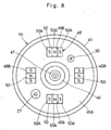
- a second embodiment of the present invention has features in that the magnetic holding mechanism is constituted by a first magnet group consisting of rows of a plural number of permanent magnets which are provided either on the side of the cartridge mount portion of the housing or on the side of the paint cartridge and alternately changed in magnetic pole position, and a second magnet group likewise consisting of rows of a plural number of permanent magnets which are provided on the other one of the cartridge mount portion of the housing and the paint cartridge and alternately changed in magnetic pole position inversely relative to confronting permanent magnets of the first magnet group.
- those component parts which are identical with the counterparts in the foregoing first embodiment are simply designated by the same or similar reference numerals to avoid repetitions of same explanations.
- a cartridge type coating machine according to the present embodiment, and at 42 a housing of the coating machine 41.
- a cartridge mount portion 43 in the form of a cylindrical cavity is formed on the rear side of a head portion 42A of a housing 42.
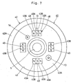
- a plural number of magnet fitting grooves 43B, for example, four magnet fitting grooves 43B are provided in a bottom surface 43A of the cartridge mount portion 43 at angularly spaced positions in the circumferential direction for attaching a first magnet group of permanent magnets 49.
- Designated at 44 is a paint cartridge according to the present embodiment, which is replaceably set in the cartridge mount portion 43 of the housing 42.
- the paint cartridge 44 is largely constituted by a container or casing 45, a conical projection 46 and a feed tube 47.
- the cartridge container 45 is formed in the shape of a hollow cylinder which is closed at the opposite ends, and provided with a plural number of magnet fitting grooves 45B, for example, four magnet fitting grooves at angularly spaced positions on its front surface 45A for attaching a second magnet group of the permanent magnets 50, which will be described hereinafter.
- a magnetic holding mechanism according to the present embodiment, which is provided between the cartridge mount portion 43 of the housing 42 and the paint cartridge 44.
- This magnetic holding mechanism 48 is provided also for detachably holding the paint cartridge 44 in the cartridge mount portion 43 of the housing 42 by magnetic attraction, and is largely constituted by first magnet groups 49 and second magnet group 50, as described below.
- the first magnet groups including, for example, four sets of permanent magnets which are fixedly set in the magnet fitting grooves 43B.
- Each one of the first magnet group 49 is composed of three permanent magnets 49A of rectangular parallelepiped shape which are arranged in a row in the circumferential direction.
- the magnetic poles (S & N) of the permanent magnets 49A are positioned inversely relative to the confronting magnets of the second magnet group 50.
- the poles of the permanent magnets 49A are arranged in the order of N-S-N.
- Indicated at 50 is a second magnet group consisting of rows of a plural number of permanent magnets, for example, four sets of permanent magnets 50A which are fixedly set in magnet fitting grooves 45B on the casing of the container 45 in confronting relation with the first magnet group 49.
- each set of the second magnet group 50 is constituted by three permanent magnets 50A of rectangular parallelepiped shape which are arranged in a row in the circumferential direction.
- the poles of the permanent magnets 50A are arranged inversely relative to the confronting permanent magnets 49A of the first magnet group 49. Namely, in the case of the particular example shown, the magnetic poles of the permanent magnets 50A are arranged in the order of S-N-S inversely to the order of magnetic poles in the first magnet group 49.
- the paint cartridge 44 as soon as the paint cartridge 44 is set on the cartridge mount portion 43 of the housing 42, it can be fixedly held in position within the cartridge mount portion 43 by the magnetic holding mechanism 48, that is, by magnetic attraction between the first magnet group 49 on the side of the housing 42 and the second magnet group 50 on the side of the paint cartridge 44.
- the magnetic poles of the permanent magnets 49A of the first magnet group 49 are arranged in the order of N-S-N, inversely to the opposing permanent magnets 50A of the second magnet group 50 which are arranged in the order of S-N-S. Therefore, as the second magnet groups 50 approaches the first magnet groups 49, homopolar repulsions and heteropolar attractions take place between the permanent magnets 50A on the side of the paint cartridge and the permanent magnets 49A on the side of the housing. It follows that positional deviations between the first magnet group 49 and the second magnet group 50, if any, can be automatically corrected to set and fix the paint cartridge 44 accurately in position relative to the housing 42.
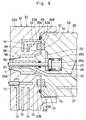
- a third embodiment of the present invention the housing of the coating machine is provided with a cartridge mount portion which is also in the shape of a bottomed cylindrical cavity, and each one of paint cartridges is largely constituted by a cylindrical container for a supply of paint and a feed tube which is extended axially forward from the container.
- the present embodiment has features in that a seal member is provided either on a bottom surface of the cartridge mount portion or on an opposing front surface of the container in such a way as to define an ejection air space by abutting engagement with the bottom surface of the cartridge mount portion or the front surface of the container for introduction of ejection air.
- those component parts which are same as or equivalent with counterparts in the foregoing first embodiment are simply indicated by the same or similar reference numerals to avoid repetitions of same explanations.
- Denoted at 61 is a cartridge type coating machine according to the present embodiment, and at 62 is a housing of the coating machine 61.
- the housing 62 is also provided with a cartridge mount portion 63 in the form of a cylindrical cavity on the rear side of its head portion 62A.
- a plural number of magnet fitting grooves 63B are formed in a bottom surface 63A of the cartridge mount portion 63 at angularly spaced positions in the circumferential direction for holding permanent magnets 33 therein.
- annular groove 63C is formed in the bottom surface 63A of the cartridge mount portion 63 at a position radially outward of the respective magnet fitting grooves 63B and the ejection air supply passage 15.
- Indicated at 64 is a paint cartridge according to the present embodiment, to be replaceably set in the cartridge mount portion 63 of the housing 62.
- This paint cartridge 64 is largely constituted by a container 65, a conical projection 66 and a feed tube 67.
- the container 65 of this embodiment is formed in a cylindrical shape which is slightly smaller in diameter than the cartridge mount portion 63 and closed at the opposite ends.
- a plural number of magnetic member fitting grooves 65B are formed in a front surface 65A of the container at angularly spaced positions in the circumferential direction for fitting magnetic members 34 therein.
- the container 65 of this embodiment differs from the container 21 of the foregoing first embodiment in that the annular groove 21D is abolished.
- Indicated at 68 is an O-ring which is fitted in the annular groove 63C on the bottom surface 63A of the cartridge mount portion 63 to serve as a seal member.
- the O-ring 68 is hermetically engaged with the front surface 65A of the container 65 when the paint cartridge 64 is loaded into the cartridge mount portion 63 of the housing, forming an ejection air space 69 between the bottom surface 63A and the front surface 65A of the container 65.
- the ejection air space 69 is expanded to separate the container 65 away from the bottom surface 63A of the cartridge mount portion 63 against the magnetic force of the magnetic holding mechanism 32, permitting to dismantle the paint cartridge 64 from the cartridge mount portion 63.
- the ejection air space 69 is defined by the O-ring 68 which is provided in the bottom surface 63A of the cartridge mount portion 63. Therefore, the O-ring 68 is simply brought into abutting engagement with the front surface 65A of the container 65, with less susceptibility to twisting deformation or sliding abrasion as compared with the conventional O-ring which is fitted around the outer periphery of the container. Thus, the arrangements of the present embodiment contribute to prolong the service life of the O-ring 68.
- the fore end of the feed tube 67 can be located at a center position in the rotary atomizing head 8. Therefore, the feed tube can supply paint smoothly toward the rotary atomizing head 8 and in such a way as to enhance the operational reliability of the cartridge type coating machine 61.
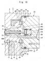
- FIG. 10 and 11 there is shown a fourth embodiment of the present invention.
- This fourth embodiment has features in that projections and recesses of complementary shapes are provided on confronting surfaces of permanent magnets and magnetic members to be coupled with each other.
- those component parts which are identical with the counterparts in the foregoing first embodiment are simply designated by the same or similar reference numerals to avoid repetitions of the same explanations.
- a magnetic holding mechanism according to the present embodiment, which is provided between the cartridge mount portion 4 of the housing 2 and a paint cartridge 20.
- This magnetic holding mechanism 71 serves to hold the paint cartridge 20 in the cartridge mount portion 4 by magnetic attraction, and largely constituted by permanent magnets 72 and magnetic members 73, which will be described hereinafter.
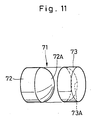
- Indicated at 72 are a plural number of permanent magnets which are fitted in magnet fitting grooves 4B on the side of the cartridge mount portion 4. As shown in Fig. 11, each one of the permanent magnets 72 is formed substantially in a short cylindrical shape. A convex projection 72A is formed on the outer surfaces of the permanent magnets 72 which confront magnetic members 73 which are provided on the side of the paint cartridge as described below.
- Indicated at 73 are a plural number of magnetic members which are set in magnetic member fitting grooves 21C on the container 21.
- Each one of the magnetic members 73 is formed substantially in a short cylindrical shape. Further, each one of the magnetic members 73 are formed with a concave recess 73A on an outer surface which confronts one of the permanent magnets 72.
- the magnetic members 73 are attracted to the permanent magnets 72 to hold the paint cartridge 20 fixedly in the cartridge mount portion 4 by magnetic force.
- the convex projection 72A of the permanent magnets 72 and the concave recesses 73A of the magnetic members 73 are formed of the gradually inclining surface, the positional deviations between the permanent magnets and the magnet members, if any, can be automatically corrected to set and fix the paint cartridge 20 accurately in position relative to the housing 2.
- a magnetic holding mechanism is constituted by electromagnets which are provided either on the side of the cartridge mount portion of the housing or on the side of a paint cartridge and magnetic member which are provided opposingly either on the side of the paint cartridge or on the side of the cartridge mount portion of the housing.
- a magnetic holding mechanism is constituted by electromagnets which are provided either on the side of the cartridge mount portion of the housing or on the side of a paint cartridge and magnetic member which are provided opposingly either on the side of the paint cartridge or on the side of the cartridge mount portion of the housing.
- the housing 82 of this embodiment is provided with a cartridge mount portion 83 in the form of a cylindrical cavity on the rear side of its head portion 82A.
- a plural number of electromagnets fitting grooves 83B are formed in a bottom surface 83A of the cartridge mount portion 83 at angularly spaced positions in the circumferential direction for fixing therein electromagnets 89 which will be described after.
- the housing 82 of this embodiment differs from the housing 2 of the first embodiment in that the ejection air supply passage 15 is abolished.
- Designated at 84 is a paint cartridge according to the present embodiment.
- the paint cartridge 84 is largely constituted by a container 85, a conical projection 86 and a feed tube 87.
- the paint cartridge 84 of this embodiment differs from the paint cartridge 20 of the first embodiment in that the annular groove 21D for the O-ring 31 is abolished from the container 85.
- Indicated at 88 is a magnetic holding mechanism according to the present embodiment, which is provided between the cartridge mount portion 83 of the housing 82 and a paint cartridge 84.
- the magnetic holding mechanism 88 functions to fixedly hold the paint cartridge 84 in the cartridge mount portion 83 by magnetic attraction.
- the magnetic holding mechanism 88 is constituted by the above-described magnetic members 34, in combination with electromagnets 89 as described below.
- each one of the electromagnets 89 is an explosion-proof electromagnet having an iron core 89A and a coil winding 89B, both clad in a molded synthetic resin material.
- the coil winding 89B is connected to a power source through wiring 89C.
- each electromagnet 89 is energized to produce magnetic force.
- the magnetic members 34 are attracted toward the electromagnets 89 to hold the paint cartridge 84 fixedly in the cartridge mount portion 83 by magnetic force.
- the paint cartridge 84 can be easily dismantled or unloaded from the cartridge mount portion 83.
- the paint cartridge 84 can be easily dismantled upon turning off power supply to and de-energizing the electromagnets 89. Accordingly, in this case, it becomes possible to omit the ejection air supply passage for simplifying the construction of the coating machine.
- the permanent magnets 33 and magnetic members 34 of the magnetic holding mechanism 32 are each shown as being in a short cylindrical shape.
- the present invention is not limited to this particular example.
- a magnetic holding mechanism 91 can be constituted by permanent magnets 92 and magnetic members 93 of tubular shape. This modification can be similarly applied to other embodiments of the present invention.
- a magnetic holding mechanism 101 consisting of tubular permanent magnets 102 and magnetic members 103, each one of the permanent magnets having arcuate projections 102A at radially opposite positions for fitting engagement with arcuate recesses or notches 103A on the side of the magnetic member 103.
- the spherical or convex projections 72A are provided on the permanent magnets 72 for fitting engagement with concave recesses 73A which are provided on the side of the magnetic members 73.
- conical projections may be provided either on the side of the magnets or on the side of the magnetic members for engagement with conical recesses or notches which are provided either on the side of the magnetic members or on the side of the magnets. If desired, the magnets and the confronting magnetic members may be engaged through projections and recesses of other shapes.
- the permanent magnets 33 and magnetic members 34 of the magnetic holding mechanism 32 are located at four angularly spaced positions in the circumferential direction.
- the present invention is not limited to the particular example shown.
- the permanent magnets 33 and magnetic members 34 may be provided at two, three or more than five different positions which are angularly spaced in the circumferential direction.
- the paint passage 23A in the feed tube 23 of the paint cartridge 20 is shown as having a function as an inlet passage for a wash fluid like thinner, in addition to functions as a paint supply passage to be used at the time of supplying paint from the paint cartridge 20 and a paint replenishing passage to be used at the time of replenishing paint into the paint cartridge 20.
- the present invention is not limited to such arrangements.
- a wash fluid passage may be provided in the container separately from the paint passage of the feed tube.
- a wash fluid passage is provided separately from a connector member which is arranged to permit paint flows into and out of the feed tube of the paint cartridge.
- a wash fluid is supplied to the paint cartridge from the wash fluid passage on the side of the paint replenisher through the wash fluid passage on the side of the cartridge.
- the cartridge mount portion 4 is formed in the shape of a flat cylindrical cavity with the bottom surface 4A, and the permanent magnets 33 are attached to the bottom surface 4A in confronting relation with the magnetic members 34 which are attached to the flat front surface 21A of the container 21.
- the present invention is not limited to the particular arrangements shown.
- the bottom surface of the cartridge mount portion with the permanent magnets and the front surface of the container casing with the magnetic members may be formed complementarily in concave and convex shapes, respectively, if desired.
- the cartridge type coating machine 1 is shown as being composed of the air motor 7 and the rotary atomizing head type sprayer unit 6 with the rotary atomizing head 8.
- the present invention is not limited to this particular type of coating machine.
- the present invention can be similarly applied to cartridge type coating machines with other sprayer units such as a hydraulic atomization type or pneumatic atomization type sprayer unit. The same applies to other embodiments of the invention.
- thinner is used as an extruding liquid for pushing paint out of the container 21 of the paint cartridge 20.
- water or other extruding liquid may be employed in place of thinner. The same applies to other embodiments of the invention.
Landscapes
- Electrostatic Spraying Apparatus (AREA)
- Spray Control Apparatus (AREA)
- Coating Apparatus (AREA)
Applications Claiming Priority (3)
| Application Number | Priority Date | Filing Date | Title |
|---|---|---|---|
| JP2001242924 | 2001-08-09 | ||
| JP2001242924 | 2001-08-09 | ||
| PCT/JP2002/007677 WO2003015932A1 (fr) | 2001-08-09 | 2002-07-29 | Machine a enduire a cartouche |
Publications (2)
| Publication Number | Publication Date |
|---|---|
| EP1433536A1 true EP1433536A1 (fr) | 2004-06-30 |
| EP1433536A4 EP1433536A4 (fr) | 2008-11-19 |
Family
ID=19073119
Family Applications (1)
| Application Number | Title | Priority Date | Filing Date |
|---|---|---|---|
| EP02755676A Withdrawn EP1433536A4 (fr) | 2001-08-09 | 2002-07-29 | Machine a enduire a cartouche |
Country Status (5)
| Country | Link |
|---|---|
| US (1) | US20030234299A1 (fr) |
| EP (1) | EP1433536A4 (fr) |
| KR (1) | KR100490915B1 (fr) |
| CA (1) | CA2421010A1 (fr) |
| WO (1) | WO2003015932A1 (fr) |
Families Citing this family (11)
| Publication number | Priority date | Publication date | Assignee | Title |
|---|---|---|---|---|
| CA2537142C (fr) | 2003-08-27 | 2013-05-28 | Toyota Jidosha Kabushiki Kaisha | Machine a enduire electrostatique et procede de nettoyage de ladite machine |
| FR2887474B1 (fr) * | 2005-06-23 | 2007-09-28 | Sames Technologies Soc Par Act | Dispositif et installation de projection de produit de revetement comportant un reservoir |
| KR101021894B1 (ko) * | 2007-02-08 | 2011-03-17 | 에이비비 가부시키가이샤 | 에어 무화형 도장 장치 |
| US8091802B2 (en) * | 2008-04-28 | 2012-01-10 | Temptu, Inc. | Spraying device apparatus |
| DE102009020077A1 (de) | 2009-05-06 | 2010-11-11 | Dürr Systems GmbH | Beschichtungsmittelvorrichtung und Beschichtungsvorrichtung |
| JP4812871B2 (ja) | 2009-10-21 | 2011-11-09 | トヨタ自動車株式会社 | 塗料充填装置 |
| JP4850944B2 (ja) * | 2009-10-21 | 2012-01-11 | トヨタ自動車株式会社 | 塗料供給方法 |
| FR3048896B1 (fr) | 2016-03-21 | 2018-04-13 | Exel Industries | Pulverisateur de produit de revetement, procede de montage et de demontage |
| BR102017008428A2 (pt) * | 2017-04-24 | 2018-11-06 | Hi Technologies S.A | leitor de amostras biológicas em testes bioquímicos rápidos |
| BR102017008549A2 (pt) | 2017-04-25 | 2018-11-21 | Hi Technologies S.A | sistema de coleta, exame e leitura de amostras biológicas em testes bioquímicos rápidos e gerenciamento de dados |
| FR3103717B1 (fr) * | 2019-12-02 | 2022-07-01 | Exel Ind | Projecteur électrostatique rotatif de produit de revêtement, installation de projection comprenant un tel projecteur et procédé de revêtement au moyen d’un tel projecteur |
Family Cites Families (19)
| Publication number | Priority date | Publication date | Assignee | Title |
|---|---|---|---|---|
| US2766909A (en) * | 1951-03-06 | 1956-10-16 | William V Doyle | Magnetic supporting device for containers |
| US3135467A (en) * | 1962-12-03 | 1964-06-02 | Greenman Leo | Automatic all color producing paint spray unit |
| US3180528A (en) * | 1963-01-25 | 1965-04-27 | Balint John | Hanging cap and holder for squeeze tubes |
| US3204601A (en) * | 1963-08-12 | 1965-09-07 | Robert B Staver | Support for an article |
| JPS59188678A (ja) * | 1983-04-09 | 1984-10-26 | Ricoh Co Ltd | トナー補給装置 |
| JPS60146265A (ja) * | 1984-01-09 | 1985-08-01 | Ricoh Co Ltd | 乾式複写機におけるトナ−補給装置 |
| US4878603B1 (en) * | 1984-01-09 | 1994-11-08 | Ricoh Kk | Toner replenishing device |
| DE8704505U1 (de) * | 1987-03-26 | 1987-09-03 | Müller, Karl-Heinz, 8540 Schwabach | Vorrichtung zum Zerstäuben eines Haarsprays |
| JPH01125190U (fr) * | 1988-02-22 | 1989-08-25 | ||
| JPH0343176A (ja) * | 1989-07-11 | 1991-02-25 | Matsushita Electric Ind Co Ltd | ツールインターフェイスユニット |
| US4948042A (en) * | 1989-07-21 | 1990-08-14 | Tench Rex D | Compressed air spray gun adapted for use with more than one canister |
| ES2077949T3 (es) * | 1991-09-26 | 1995-12-01 | Leifheit Ag | Anaquel para especias. |
| TW240299B (fr) * | 1992-12-30 | 1995-02-11 | Ricoh Kk | |
| JP3013734B2 (ja) * | 1995-03-01 | 2000-02-28 | トヨタ自動車株式会社 | 回転霧化静電塗装装置、および回転霧化静電塗装装置の塗装ガン本体へ塗料タンクユニットを装着する方法、並びに回転霧化静電塗装装置の塗料タンクユニット |
| DE19632326C1 (de) * | 1996-08-10 | 1998-01-15 | Herberts Gmbh | Vorrichtung und Verfahren zur Serienlackierung von Kraftfahrzeugkarossen |
| US5704579A (en) * | 1996-08-26 | 1998-01-06 | Ford Global Technologies, Inc. | Drink container holder usable especially in automotive vehicles |
| ES2273444T3 (es) * | 1998-01-13 | 2007-05-01 | Abb K.K. | Metodo de recubrimiento para un dispositivo de recubrimiento del tipo de cabezal atomizador rotativo. |
| EP0967016B1 (fr) * | 1998-01-13 | 2004-11-10 | Abb K.K. | Dispositif de revetement de type tete de pulverisation rotative |
| JP3263373B2 (ja) * | 1998-12-18 | 2002-03-04 | エービービー株式会社 | 自動塗装装置 |
-
2002
- 2002-07-29 CA CA002421010A patent/CA2421010A1/fr not_active Abandoned
- 2002-07-29 EP EP02755676A patent/EP1433536A4/fr not_active Withdrawn
- 2002-07-29 US US10/399,786 patent/US20030234299A1/en not_active Abandoned
- 2002-07-29 WO PCT/JP2002/007677 patent/WO2003015932A1/fr not_active Ceased
- 2002-07-29 KR KR10-2003-7003764A patent/KR100490915B1/ko not_active Expired - Fee Related
Also Published As
| Publication number | Publication date |
|---|---|
| EP1433536A4 (fr) | 2008-11-19 |
| KR100490915B1 (ko) | 2005-05-19 |
| CA2421010A1 (fr) | 2003-02-27 |
| KR20030039370A (ko) | 2003-05-17 |
| US20030234299A1 (en) | 2003-12-25 |
| WO2003015932A1 (fr) | 2003-02-27 |
Similar Documents
| Publication | Publication Date | Title |
|---|---|---|
| EP1433536A1 (fr) | Machine a enduire a cartouche | |
| KR100354662B1 (ko) | 자동도장장치 | |
| US6666164B2 (en) | Automatic coating method and apparatus | |
| CA2282591C (fr) | Systeme de revetement a type tete de pulverisation rotative | |
| US4936510A (en) | Rotary automizer with air cap and retainer | |
| EP2305387B1 (fr) | Dispositif de revêtement à tête rotative d atomisation | |
| US6179217B1 (en) | Coating method for rotary atomizing head type coating device | |
| EP2117720B1 (fr) | Buse de pulvérisation par atomisation d'air à soupape de coupure actionnée magnétiquement | |
| US6284047B1 (en) | Rotary atomizing head type coating device | |
| EP0480226A1 (fr) | Fixation du capuchon à air d'un atomiseur rotatif à palier à air | |
| US4936507A (en) | Rotary atomizer with high voltage isolating speed measurement | |
| JP4205380B2 (ja) | カートリッジ式塗装装置 | |
| JPH11262699A (ja) | 回転霧化頭型塗装装置 | |
| US4936509A (en) | Air turbine driven rotary atomizer | |
| CN217165012U (zh) | 一种喷涂设备 | |
| CN220658058U (zh) | 一种粉泵清吹组件及粉泵 | |
| JP2000240402A (ja) | エアモータ | |
| JP2004344889A (ja) | 回転霧化頭型塗装装置の塗装方法 | |
| JP2026034992A (ja) | 粉体塗装システム | |
| CN119488996A (zh) | 包括旋转碗和磁性连接装置的旋转雾化器、以及组装和/或拆卸这种雾化器的方法 | |
| JP2023541468A (ja) | 回転アトマイザ |
Legal Events
| Date | Code | Title | Description |
|---|---|---|---|
| PUAI | Public reference made under article 153(3) epc to a published international application that has entered the european phase |
Free format text: ORIGINAL CODE: 0009012 |
|
| 17P | Request for examination filed |
Effective date: 20030221 |
|
| AK | Designated contracting states |
Kind code of ref document: A1 Designated state(s): AT BE BG CH CY CZ DE DK EE ES FI FR GB GR IE IT LI LU MC NL PT SE SK TR |
|
| A4 | Supplementary search report drawn up and despatched |
Effective date: 20081017 |
|
| 17Q | First examination report despatched |
Effective date: 20090112 |
|
| STAA | Information on the status of an ep patent application or granted ep patent |
Free format text: STATUS: THE APPLICATION IS DEEMED TO BE WITHDRAWN |
|
| 18D | Application deemed to be withdrawn |
Effective date: 20090526 |