EP1433666A1 - Zündeinrichtung zum Anschluss an einen Datenbus - Google Patents
Zündeinrichtung zum Anschluss an einen Datenbus Download PDFInfo
- Publication number
- EP1433666A1 EP1433666A1 EP03258152A EP03258152A EP1433666A1 EP 1433666 A1 EP1433666 A1 EP 1433666A1 EP 03258152 A EP03258152 A EP 03258152A EP 03258152 A EP03258152 A EP 03258152A EP 1433666 A1 EP1433666 A1 EP 1433666A1
- Authority
- EP
- European Patent Office
- Prior art keywords
- ignition
- communication
- control system
- package
- circuit
- Prior art date
- Legal status (The legal status is an assumption and is not a legal conclusion. Google has not performed a legal analysis and makes no representation as to the accuracy of the status listed.)
- Granted
Links
- XUIMIQQOPSSXEZ-UHFFFAOYSA-N Silicon Chemical compound [Si] XUIMIQQOPSSXEZ-UHFFFAOYSA-N 0.000 claims abstract description 23
- 229910052710 silicon Inorganic materials 0.000 claims abstract description 20
- 239000010703 silicon Substances 0.000 claims abstract description 20
- 239000003795 chemical substances by application Substances 0.000 claims description 8
- 229920003002 synthetic resin Polymers 0.000 claims description 2
- 239000000057 synthetic resin Substances 0.000 claims description 2
- 230000003247 decreasing effect Effects 0.000 abstract description 2
- 230000001133 acceleration Effects 0.000 description 6
- 239000003380 propellant Substances 0.000 description 6
- 238000002485 combustion reaction Methods 0.000 description 2
- 238000010586 diagram Methods 0.000 description 1
- 230000000694 effects Effects 0.000 description 1
- 238000010438 heat treatment Methods 0.000 description 1
- 238000003754 machining Methods 0.000 description 1
- 238000004519 manufacturing process Methods 0.000 description 1
- 230000004048 modification Effects 0.000 description 1
- 238000012986 modification Methods 0.000 description 1
Images


Classifications
-
- B—PERFORMING OPERATIONS; TRANSPORTING
- B60—VEHICLES IN GENERAL
- B60R—VEHICLES, VEHICLE FITTINGS, OR VEHICLE PARTS, NOT OTHERWISE PROVIDED FOR
- B60R21/00—Arrangements or fittings on vehicles for protecting or preventing injuries to occupants or pedestrians in case of accidents or other traffic risks
- B60R21/01—Electrical circuits for triggering passive safety arrangements, e.g. airbags, safety belt tighteners, in case of vehicle accidents or impending vehicle accidents
- B60R21/017—Electrical circuits for triggering passive safety arrangements, e.g. airbags, safety belt tighteners, in case of vehicle accidents or impending vehicle accidents including arrangements for providing electric power to safety arrangements or their actuating means, e.g. to pyrotechnic fuses or electro-mechanic valves
-
- B—PERFORMING OPERATIONS; TRANSPORTING
- B60—VEHICLES IN GENERAL
- B60R—VEHICLES, VEHICLE FITTINGS, OR VEHICLE PARTS, NOT OTHERWISE PROVIDED FOR
- B60R21/00—Arrangements or fittings on vehicles for protecting or preventing injuries to occupants or pedestrians in case of accidents or other traffic risks
- B60R21/02—Occupant safety arrangements or fittings, e.g. crash pads
- B60R21/16—Inflatable occupant restraints or confinements designed to inflate upon impact or impending impact, e.g. air bags
- B60R21/26—Inflatable occupant restraints or confinements designed to inflate upon impact or impending impact, e.g. air bags characterised by the inflation fluid source or means to control inflation fluid flow
-
- F—MECHANICAL ENGINEERING; LIGHTING; HEATING; WEAPONS; BLASTING
- F42—AMMUNITION; BLASTING
- F42B—EXPLOSIVE CHARGES, e.g. FOR BLASTING, FIREWORKS, AMMUNITION
- F42B3/00—Blasting cartridges, i.e. case and explosive
- F42B3/10—Initiators therefor
- F42B3/12—Bridge initiators
- F42B3/121—Initiators with incorporated integrated circuit
-
- B—PERFORMING OPERATIONS; TRANSPORTING
- B60—VEHICLES IN GENERAL
- B60R—VEHICLES, VEHICLE FITTINGS, OR VEHICLE PARTS, NOT OTHERWISE PROVIDED FOR
- B60R21/00—Arrangements or fittings on vehicles for protecting or preventing injuries to occupants or pedestrians in case of accidents or other traffic risks
- B60R21/01—Electrical circuits for triggering passive safety arrangements, e.g. airbags, safety belt tighteners, in case of vehicle accidents or impending vehicle accidents
- B60R2021/0104—Communication circuits for data transmission
- B60R2021/01047—Architecture
- B60R2021/01054—Bus
- B60R2021/01075—Bus between the airbag control unit and pyrotechnic fuses or equivalent actuators
-
- B—PERFORMING OPERATIONS; TRANSPORTING
- B60—VEHICLES IN GENERAL
- B60R—VEHICLES, VEHICLE FITTINGS, OR VEHICLE PARTS, NOT OTHERWISE PROVIDED FOR
- B60R21/00—Arrangements or fittings on vehicles for protecting or preventing injuries to occupants or pedestrians in case of accidents or other traffic risks
- B60R21/02—Occupant safety arrangements or fittings, e.g. crash pads
- B60R21/16—Inflatable occupant restraints or confinements designed to inflate upon impact or impending impact, e.g. air bags
- B60R21/26—Inflatable occupant restraints or confinements designed to inflate upon impact or impending impact, e.g. air bags characterised by the inflation fluid source or means to control inflation fluid flow
- B60R2021/26029—Ignitors
Definitions
- the present invention relates to an ignition device for bus connection, a plurality of the ignition devices being connected to an ignition control system via a common bus, and the ignition devices being selectively operable by means of electrical energy and an electrical signal supplied from the ignition control system.
- An airbag device mounted in an automobile is arranged so that an airbag is inflated by high pressure gas generated by combustion of a propellant, and an ignition device (an igniter or a squib) for igniting the propellant is provided in the airbag device.
- the ignition device is connected to an ignition control system, into which an acceleration signal generated upon a vehicle collision is input. Energizing an ignition element of the ignition device generates heat to ignite the propellant, thereby inflating the airbag.
- Recent automobiles are equipped with a large number of airbag devices such as an airbag device that deploys from a steering wheel, an airbag device that deploys from a dashboard, an airbag device that deploys from a seat side part, and an airbag device that deploys from a roof side part. Therefore, the number of circuits within the ignition control system have to be increased in line with the number of the airbag devices, and each time the number of airbag devices increases the ignition control system has to be changed even for the same type of vehicle. In each case the production cost increases. Furthermore, if the ignition control system and each of the airbag devices are connected by means of a harness exclusively used therefor, the harness becomes very long, and it is difficult to ensure space for arranging the harness.
- US Patent No. 5,760,489 discloses an arrangement in which a plurality of airbag devices are connected to a common bus extending from an ignition control system, electrical energy for ignition is supplied from the ignition control system to an ignition device of each of the airbag devices, and an electrical signal is also supplied for operating only the ignition device of a predetermined airbag device among the plurality of airbag devices.
- the ignition device of each of the airbag devices requires a communication circuit for communicating with the ignition control system and an ignition circuit for making an ignition element generate heat when it receives an ignition command during the communication.
- Such an ignition device comprising a communication/ignition circuit is known from US Patent No. 6,418,853.
- the ignition device (an igniter 1) is provided separately with the communication/ignition circuit (an electronic card 17) for outputting an ignition signal in communication with the ignition control system (a central control unit 110), and the ignition element (a resistive heating element 11), which is operated by the ignition signal output from the communication/ignition circuit so as to ignite a propellant (a pyrotechnic ignition composition 7). Therefore, not only do the dimensions of the ignition device increase, but also it is necessary to connect a wire between the communication/ignition circuit and the ignition element when assembling the ignition device, thus disadvantageously increasing the number of assembly steps.
- the present invention has been achieved in view of the above-mentioned circumstances, and it is an object thereof to reduce the dimensions of an ignition device for bus connection and decrease the number of wiring steps during assembly of the ignition device.
- a first aspect of the present invention provides an ignition device for bus connection, of a type in which a plurality of the ignition devices are connected to an ignition control system via a common bus, and the ignition devices are selectively operable by means of electrical energy and an electrical signal supplied from the ignition control system, wherein the ignition device comprises an ignition package integrally comprising a communication/ignition circuit provided on a silicon chip and an ignition element provided on a silicon chip.
- the ignition device for bus connection is connected to the ignition control system via the common bus and comprises the ignition package integrally comprising the communication/ignition circuit and the ignition element provided on the silicon chip(s). Therefore, not only can the dimensions of the ignition device for bus connection be reduced in comparison with a case in which the communication/ignition circuit and the ignition element are separately provided, but also wiring between the communication/ignition circuit and the ignition element can be completed beforehand while the ignition device for bus connection is being produced, thereby decreasing the number of wiring steps during assembly of the ignition device with the ignition control system.
- a second aspect of the present invention provides an ignition device for bus connection, of a type in which a plurality of the ignition devices are connected to an ignition control system via a common bus, and the ignition devices are selectively operable by means of electrical energy and an electrical signal supplied from the ignition control system, wherein the ignition device comprises:
- the communication/ignition circuit and the ignition element are provided on the common silicon chip, the number of components can be reduced in comparison with a case in which the communication/ignition circuit and the ignition element are provided individually on separate silicon chips. Furthermore, a bridge wire for providing a connection between the communication/ignition circuit and the ignition element can be omitted, thereby further reducing the number of components and the number of wiring steps.
- the ignition package is used as a header of the ignition device.
- the ignition package since the ignition package is used as the header, it is unnecessary to provide a special header, thereby contributing to a reduction in the number of components.
- Silicon chip 27, or first and second silicon chips 27a and 27b in the disclosed embodiments correspond to the silicon chip of the present invention.
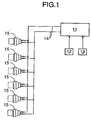
- a first acceleration sensor 12 for detecting a head-on collision of a vehicle
- a second acceleration sensor 13 for detecting a side collision of the vehicle.
- a bus 14 extending from the ignition control system 11 are a plurality of ignition devices 15, which are, in the embodiment, a total of six ignition devices 15 provided on each of an airbag device that deploys from a steering wheel, an airbag device that deploys from a dashboard, two airbag devices that deploy from left and right seats, and two airbag devices that deploy from left and right side parts of a roof.
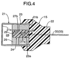
- each of the ignition devices 15 comprises a cylindrical casing 21 having a bottom 21a, a connector portion 22 joined so as to cover the outer side of an opening 21b of the casing 21, a header 23 fixed so as to block the opening 21b of the casing 21, an ignition package 24 fixed so as to run through a through hole 23a of the header 23, and an igniting agent 25 disposed so as to cover a part of the ignition package 24 projecting from the header 23 toward the bottom 21 a of the casing 21.
- a space 26 is formed between the bottom 21 a of the casing 21 and the igniting agent 25.
- the ignition device 15 comprises a communication/ignition circuit 28 and an ignition element 29 provided on the surface of a plate-shaped silicon chip 27, and they are connected to each other via leads 30 and 31 printed on the silicon chip 27. Base ends of two pins 32 and 33 running through the connector portion 22 are connected to the communication/ignition circuit 28 via two bridge wires 34 and 35.
- the silicon chip 27, the communication/ignition circuit 28, the ignition element 29, the two bridge wires 34 and 35, and the base ends of the two pins 32 and 33 are embedded in a synthetic resin, thus forming the ignition package 24.
- the ignition package 24 has an opening 24a, through which the ignition element 29 is exposed, and the opening 24a is filled with a portion of the igniting agent 25.
- the ignition device 15 having such a structure is mounted at a position adjacent to a propellant of an inflator (a gas generating device) of the airbag device, and the two pins 32 and 33 are connected to the bus 14.
- the ignition control system 11 When the vehicle is involved in a collision and the first acceleration sensor 12 or the second acceleration sensor 13 detects acceleration at a predetermined value or higher, the ignition control system 11 outputs a deployment command signal to the bus 14 in order to operate a predetermined airbag device.
- the ignition device 15 of the airbag device into which the deployment command signal has been input determines in the communication/ignition circuit 28 thereof whether or not the deployment command signal is a command to operate its own airbag device and, if it is a command to operate its own airbag device, energizes the ignition element 29 as to generate heat.
- the electrical energy for making the ignition element 29 generate heat is stored beforehand in storage means provided in the communication/ignition circuit 28, thereby alleviating the load on the power source when a plurality of airbag devices are operated simultaneously.
- the igniting agent 25 in contact with the ignition element 29 exposed through the opening 24a of the ignition package 24 ignites to burn, and the resulting heat and pressure break the bottom 21a of the casing 21, causing the propellant of the inflator to ignite and generate high-pressure gas, so that the high-pressure gas deploys the airbag. Since the opening 21b of the casing 21 is blocked by the header 23, the heat and pressure generated by the combustion of the igniting agent 25 can be directed to the bottom 21a of the casing 21.
- the communication/ignition circuit 28 and the ignition element 29 of the ignition device 15 are integrated and contained within the ignition package 24, the dimensions of the ignition device 15 can be reduced to similar levels to those of a conventional ignition device which is individually connected to the ignition control system 11 without the bus 14.
- a conventional airbag device can be connected to the bus 14 without any modification, thereby contributing to a reduction in cost.
- the communication/ignition circuit 28 and the ignition element 29 are provided on the common silicon chip 27, not only can the number of components be reduced and the dimensions of the ignition device 15 be further reduced, but also it is unnecessary to connect a bridge wire between the communication/ignition circuit 28 and the ignition element 29, thereby reducing the number of processing steps.
- the number of wiring steps can also be reduced.
- the communication/ignition circuit 28 and the ignition element 29 are provided on the common silicon chip 27, but in the second embodiment a first silicon chip 27a having a communication/ignition circuit 28 thereon and a second silicon chip 27b having an ignition element 29 thereon are formed as separate members, and the communication/ignition circuit 28 and the ignition element 29 are connected to each other via a bridge wire (not illustrated).
- the ignition element 29 can be exposed directly on the surface of an ignition package 24, and it is unnecessary to form an opening 24a (see FIG. 3) in the ignition package 24, thus reducing the number of machining steps. Moreover, since connection of a bridge wire between the communication/ignition circuit 28 and the ignition element 29 can be completed when producing an ignition device 15, there is no need to carry out special wiring when assembling the ignition device 15, thereby reducing the number of wiring steps.
- a third embodiment of the present invention is now explained with reference to FIG. 5.
- the ignition package 24 of the first embodiment is turned through 90° so as to make the opening 24a of the ignition package 24 face the back side of the ignition agent 25.
- This third embodiment can exhibit the same effects as those of the first embodiment.
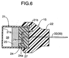
- the fourth embodiment is an improvement of the third embodiment; an opening 21b of a casing 21 is blocked directly by means of an ignition package 24, thus omitting the header 23 (see FIG. 5) and further reducing the number of components.
- the ignition device for bus connection of the present invention is applicable to an airbag device of an automobile, but it is applicable to a pretensioner of a seat belt system of an automobile, and can also be used in any application other than automobiles.
Landscapes
- Engineering & Computer Science (AREA)
- Mechanical Engineering (AREA)
- Computer Hardware Design (AREA)
- Microelectronics & Electronic Packaging (AREA)
- General Engineering & Computer Science (AREA)
- Physics & Mathematics (AREA)
- Fluid Mechanics (AREA)
- Air Bags (AREA)
Applications Claiming Priority (2)
| Application Number | Priority Date | Filing Date | Title |
|---|---|---|---|
| JP2002376637 | 2002-12-26 | ||
| JP2002376637A JP3803636B2 (ja) | 2002-12-26 | 2002-12-26 | バス接続用点火装置 |
Publications (2)
| Publication Number | Publication Date |
|---|---|
| EP1433666A1 true EP1433666A1 (de) | 2004-06-30 |
| EP1433666B1 EP1433666B1 (de) | 2005-11-09 |
Family
ID=32463572
Family Applications (1)
| Application Number | Title | Priority Date | Filing Date |
|---|---|---|---|
| EP03258152A Expired - Lifetime EP1433666B1 (de) | 2002-12-26 | 2003-12-24 | Zündeinrichtung zum Anschluss an einen Datenbus |
Country Status (4)
| Country | Link |
|---|---|
| US (1) | US7161790B2 (de) |
| EP (1) | EP1433666B1 (de) |
| JP (1) | JP3803636B2 (de) |
| DE (1) | DE60302202T2 (de) |
Cited By (1)
| Publication number | Priority date | Publication date | Assignee | Title |
|---|---|---|---|---|
| CN108592707A (zh) * | 2018-07-27 | 2018-09-28 | 中国工程物理研究院化工材料研究所 | 一种微机电智能安全起爆装置及其制备方法 |
Families Citing this family (17)
| Publication number | Priority date | Publication date | Assignee | Title |
|---|---|---|---|---|
| US6820557B2 (en) * | 2002-01-25 | 2004-11-23 | Daicel Chemical Industries, Ltd. | Igniter for air bag system |
| US7343859B2 (en) | 2003-11-10 | 2008-03-18 | Honda Motor Co., Ltd. | Squib |
| JP4094529B2 (ja) | 2003-11-10 | 2008-06-04 | 本田技研工業株式会社 | 着火装置 |
| JP3917127B2 (ja) | 2003-12-08 | 2007-05-23 | 本田技研工業株式会社 | 着火装置 |
| US20050189753A1 (en) * | 2004-02-10 | 2005-09-01 | Kazuhiro Kato | Gas generator |
| WO2006061879A1 (ja) * | 2004-12-06 | 2006-06-15 | Renesas Technology Corp. | 点火装置、半導体装置及びその製造方法 |
| JP4813904B2 (ja) * | 2006-01-06 | 2011-11-09 | 日本化薬株式会社 | 点火装置およびその製造方法ならびにエアバッグ用ガス発生装置およびシートベルトプリテンショナー用ガス発生装置 |
| JP4996481B2 (ja) * | 2006-01-06 | 2012-08-08 | 日本化薬株式会社 | 点火装置ならびにエアバッグ用ガス発生装置およびシートベルトプリテンショナー用ガス発生装置 |
| US8408131B1 (en) | 2006-09-29 | 2013-04-02 | Reynolds Systems, Inc. | Energetic material initiation device |
| US7571679B2 (en) * | 2006-09-29 | 2009-08-11 | Reynolds Systems, Inc. | Energetic material initiation device having integrated low-energy exploding foil initiator header |
| US7762189B2 (en) * | 2006-12-29 | 2010-07-27 | Pacific Scientific Energetic Materials Company | Networked pyrotechnic actuator incorporating high-pressure bellows |
| DE102007023322B4 (de) * | 2007-05-16 | 2017-05-18 | Volkswagen Ag | Personenschutzsystem für ein Fahrzeug und zugehöriges Verfahren |
| US8276516B1 (en) | 2008-10-30 | 2012-10-02 | Reynolds Systems, Inc. | Apparatus for detonating a triaminotrinitrobenzene charge |
| FR2959303B1 (fr) * | 2010-04-27 | 2012-04-06 | Nexter Munitions | Dispositif d'amorcage a initiation electrique pour projectile |
| DE102013017383A1 (de) | 2013-10-21 | 2015-04-23 | Trw Airbag Systems Gmbh | Anzündeinheit, insbesondere für einen Gasgenerator, Gasgenerator, Gassackmodul, Fahrzeugsicherheitssystem und Verfahren zur Herstellung einer Anzündeinheit |
| JP6781072B2 (ja) * | 2017-02-24 | 2020-11-04 | 日本化薬株式会社 | 点火器および当該点火器を備えるガス発生器 |
| US10471927B1 (en) * | 2017-09-13 | 2019-11-12 | Waymo Llc | Tethered airbags |
Citations (5)
| Publication number | Priority date | Publication date | Assignee | Title |
|---|---|---|---|---|
| EP0802092A1 (de) * | 1996-04-15 | 1997-10-22 | Morton International, Inc. | Hochdruckbeständiger Initialzünder mit integralem Metalloxidvaristor zum Schutz gegen elektrostatische Entladungen |
| US20010022146A1 (en) * | 1997-03-07 | 2001-09-20 | Daniel Duvacquier | Electro-pyrotechnic initiator built around a complete printed circuit |
| WO2002001078A1 (fr) * | 2000-06-30 | 2002-01-03 | Etienne Lacroix Tous Artifices S.A. | Actionneur a base de micro-impulseurs pyrotechniques |
| US6418853B1 (en) * | 1999-02-18 | 2002-07-16 | Livbag Snc | Electropyrotechnic igniter with integrated electronics |
| DE10161515A1 (de) * | 2001-01-05 | 2002-09-19 | Trw Inc | Airbag-Aufblasvorrichtungen |
Family Cites Families (12)
| Publication number | Priority date | Publication date | Assignee | Title |
|---|---|---|---|---|
| DE3626663A1 (de) * | 1986-08-07 | 1988-02-11 | Roehm Gmbh | Bindemittel fuer formsande |
| US5847309A (en) * | 1995-08-24 | 1998-12-08 | Auburn University | Radio frequency and electrostatic discharge insensitive electro-explosive devices having non-linear resistances |
| US6085659A (en) * | 1995-12-06 | 2000-07-11 | Orica Explosives Technology Pty Ltd | Electronic explosives initiating device |
| US5760489A (en) | 1996-10-04 | 1998-06-02 | Motorola, Inc. | Method for transmitting signals between a microprocessor and an interface circuit |
| DE19756563C1 (de) | 1997-12-18 | 1999-08-19 | Siemens Ag | Integrierte Schaltungsanordnung zum Aufheizen von Zündmaterial sowie Verwendung einer solchen integrierten Schaltungsanordnung |
| DE19815928C2 (de) | 1998-04-09 | 2000-05-11 | Daimler Chrysler Ag | Halbleiterzünder mit verbesserter konstruktiver Festigkeit |
| DE19819428C1 (de) | 1998-04-30 | 1999-11-18 | Daimler Chrysler Ag | Anzündelement |
| US6166452A (en) * | 1999-01-20 | 2000-12-26 | Breed Automotive Technology, Inc. | Igniter |
| GB2369447B (en) | 2000-07-29 | 2004-06-23 | Newson Gale Ltd | Electrical resistance monitoring device |
| DE10123285A1 (de) * | 2001-05-12 | 2002-11-14 | Conti Temic Microelectronic | Zündelement für pyrotechnische Wirkmassen auf einer Schaltungsträgeranordnung mit einer Zündelektronikbaugruppe |
| DE10123284A1 (de) * | 2001-05-12 | 2002-11-14 | Conti Temic Microelectronic | Pyrotechnische Zündeinrichtung mit integrierter Elektronikbaugruppe |
| EP1396394A4 (de) | 2001-05-15 | 2004-12-08 | Nippon Kayaku Kk | Gaserzeuger |
-
2002
- 2002-12-26 JP JP2002376637A patent/JP3803636B2/ja not_active Expired - Fee Related
-
2003
- 2003-12-24 EP EP03258152A patent/EP1433666B1/de not_active Expired - Lifetime
- 2003-12-24 DE DE60302202T patent/DE60302202T2/de not_active Expired - Lifetime
- 2003-12-30 US US10/749,459 patent/US7161790B2/en not_active Expired - Fee Related
Patent Citations (5)
| Publication number | Priority date | Publication date | Assignee | Title |
|---|---|---|---|---|
| EP0802092A1 (de) * | 1996-04-15 | 1997-10-22 | Morton International, Inc. | Hochdruckbeständiger Initialzünder mit integralem Metalloxidvaristor zum Schutz gegen elektrostatische Entladungen |
| US20010022146A1 (en) * | 1997-03-07 | 2001-09-20 | Daniel Duvacquier | Electro-pyrotechnic initiator built around a complete printed circuit |
| US6418853B1 (en) * | 1999-02-18 | 2002-07-16 | Livbag Snc | Electropyrotechnic igniter with integrated electronics |
| WO2002001078A1 (fr) * | 2000-06-30 | 2002-01-03 | Etienne Lacroix Tous Artifices S.A. | Actionneur a base de micro-impulseurs pyrotechniques |
| DE10161515A1 (de) * | 2001-01-05 | 2002-09-19 | Trw Inc | Airbag-Aufblasvorrichtungen |
Cited By (2)
| Publication number | Priority date | Publication date | Assignee | Title |
|---|---|---|---|---|
| CN108592707A (zh) * | 2018-07-27 | 2018-09-28 | 中国工程物理研究院化工材料研究所 | 一种微机电智能安全起爆装置及其制备方法 |
| CN108592707B (zh) * | 2018-07-27 | 2023-11-03 | 中国工程物理研究院化工材料研究所 | 一种微机电智能安全起爆装置及其制备方法 |
Also Published As
| Publication number | Publication date |
|---|---|
| JP2004203294A (ja) | 2004-07-22 |
| US20050188875A1 (en) | 2005-09-01 |
| DE60302202D1 (de) | 2005-12-15 |
| EP1433666B1 (de) | 2005-11-09 |
| DE60302202T2 (de) | 2006-06-01 |
| US7161790B2 (en) | 2007-01-09 |
| JP3803636B2 (ja) | 2006-08-02 |
Similar Documents
| Publication | Publication Date | Title |
|---|---|---|
| US7161790B2 (en) | Ignition device for bus connection | |
| US5158323A (en) | Airbag restraint system for motor vehicle | |
| JP4065582B2 (ja) | 自動車用エアバッグ・システム | |
| US6191949B1 (en) | Application specific integrated circuit package and initiator employing same | |
| EP2925568B1 (de) | Elektrische riemenanordnung zur beidseitigen aktivierung für kraftfahrzeugrückhaltesysteme | |
| JP2013244757A (ja) | 乗員保護装置 | |
| US7404573B2 (en) | Gas generator | |
| JP6289490B2 (ja) | 膨張可能な拘束具用の2重作動システム | |
| JP2004284452A (ja) | エアバッグシステム | |
| EP1529697B1 (de) | Zündpille | |
| EP1559615B1 (de) | Zündkreis für air-bag Zündpille | |
| EP1544570B1 (de) | Zünder | |
| US7398852B2 (en) | Noise-resistant circuit and apparatus using same | |
| JP4397731B2 (ja) | 点火装置 | |
| JP3917127B2 (ja) | 着火装置 | |
| KR100468540B1 (ko) | 스티어링휠의 에어백모듈 설치구조 | |
| JP2005180737A (ja) | スクイブ | |
| JP2005201628A (ja) | スクイブ | |
| WO2024063156A1 (ja) | スクイブ発火回路 | |
| JP4260611B2 (ja) | 乗員保護装置、及び乗員保護装置の点火制御装置と着火装置 | |
| KR100398100B1 (ko) | 2단 전개식 에어백용 인플레이터 | |
| JP2008013031A (ja) | 着火装置 | |
| JPH06312642A (ja) | エアバッグ装置 | |
| JP2001347919A (ja) | 多段式エアバッグ装置及びそれに用いるガス発生器 | |
| KR20060053705A (ko) | 에어백 제어장치 |
Legal Events
| Date | Code | Title | Description |
|---|---|---|---|
| PUAI | Public reference made under article 153(3) epc to a published international application that has entered the european phase |
Free format text: ORIGINAL CODE: 0009012 |
|
| AK | Designated contracting states |
Kind code of ref document: A1 Designated state(s): AT BE BG CH CY CZ DE DK EE ES FI FR GB GR HU IE IT LI LU MC NL PT RO SE SI SK TR |
|
| AX | Request for extension of the european patent |
Extension state: AL LT LV MK |
|
| 17P | Request for examination filed |
Effective date: 20040618 |
|
| 17Q | First examination report despatched |
Effective date: 20040810 |
|
| AKX | Designation fees paid |
Designated state(s): DE GB |
|
| GRAP | Despatch of communication of intention to grant a patent |
Free format text: ORIGINAL CODE: EPIDOSNIGR1 |
|
| GRAS | Grant fee paid |
Free format text: ORIGINAL CODE: EPIDOSNIGR3 |
|
| RBV | Designated contracting states (corrected) |
Designated state(s): DE GB |
|
| GRAA | (expected) grant |
Free format text: ORIGINAL CODE: 0009210 |
|
| AK | Designated contracting states |
Kind code of ref document: B1 Designated state(s): DE GB |
|
| REG | Reference to a national code |
Ref country code: GB Ref legal event code: FG4D |
|
| REF | Corresponds to: |
Ref document number: 60302202 Country of ref document: DE Date of ref document: 20051215 Kind code of ref document: P |
|
| PLBE | No opposition filed within time limit |
Free format text: ORIGINAL CODE: 0009261 |
|
| STAA | Information on the status of an ep patent application or granted ep patent |
Free format text: STATUS: NO OPPOSITION FILED WITHIN TIME LIMIT |
|
| 26N | No opposition filed |
Effective date: 20060810 |
|
| PGFP | Annual fee paid to national office [announced via postgrant information from national office to epo] |
Ref country code: GB Payment date: 20091223 Year of fee payment: 7 |
|
| PGFP | Annual fee paid to national office [announced via postgrant information from national office to epo] |
Ref country code: DE Payment date: 20091217 Year of fee payment: 7 |
|
| GBPC | Gb: european patent ceased through non-payment of renewal fee |
Effective date: 20101224 |
|
| REG | Reference to a national code |
Ref country code: DE Ref legal event code: R119 Ref document number: 60302202 Country of ref document: DE Effective date: 20110701 |
|
| PG25 | Lapsed in a contracting state [announced via postgrant information from national office to epo] |
Ref country code: GB Free format text: LAPSE BECAUSE OF NON-PAYMENT OF DUE FEES Effective date: 20101224 Ref country code: DE Free format text: LAPSE BECAUSE OF NON-PAYMENT OF DUE FEES Effective date: 20110701 |